Thank you for choosing Lightware’s MX-FR hybrid modular matrix switcher. In the first chapter we would like to introduce the device, highlighting the most important features in the listed sections below:
1.1. Description
Thank you for choosing Lightware matrix routers. The hybrid modular matrix routers are capable of routing DVI or HDMI signals in a scalable non-blocking crosspoint configuration, with up to 80 inputs and 80 outputs.
These products are designed according to our well known philosophy of ‘High Fidelity Signal Management’. The 2011 series router frames and I/O board family incorporate new features, broader signal compatibility, more precise switching, control, troubleshooting and signal measurement.
The router frames start from 9x9 I/O size and increase up to 80x80. AV professionals can choose between various I/O sizes, video signal types and transport media options according to their system requirements thanks to our Hybrid Modular Design.
The future-proofed matrix backplanes are able to switch to 12.8 Gigabit per second data rates, allowing transportation of the next generation HDMI, 4K x 2K, 3D and DisplayPort 1.1 video signals. All Input boards e.g. DVI-I, 3G-SDI, etc. convert their respective Input signals to the widest and broadest standard for all existing video signals – uncompressed HDMI (including embedded audio). Output boards convert the router’s switched HDMI format to their respective output e.g. Fiber and Twisted Pair, amongst others.
Model Denomination

About the Serial Number
Lightware devices contain a label indicating the unique serial number of the product. The structure is the following:


|
Non-blocking Crosspoint Matrix Architecture |
|
The router allows any input to be switched to any output or more outputs simultaneously. |
|

|
Hybrid Modular System |
|
Custom I/O sizes with several types of input and output boards give the flexibility for interfacing with different video sources and displays. |
|

|
4K UHD & 3D Formats Support Without Latency |
|
The MX Series supports the highest 4K UHD, 2560x1600 and 1920x1080@120Hz resolutions, standard HDMI 3D formats and all HDMI 1.3 resolutions, operating without signal latency. |
|

|
Supports All HDTV Resolutions and HDCP |
|
720p, 1080i and 1080p etc. signals are supported with or without HDCP encryption. |
|

|
3D Support |
|
Lightware provides complex, integrated solutions for the digital age, also delivering 3D content in the case of certain I/O boards. |
|

|
UMX Technology |
|
UMX (Universal MatriX) technology was developed to support various analog and digital video and audio signal formats with several input connection possibilities. |
|

|
HDCP Capability |
|
Relevant I/O boards are fully HDCP compliant. Both HDCP-encrypted and non-HDCP components can be installed in the same system within the same chassis. |
|

|
No Signal Latency With Zero Frame Delay |
|
The signal management architecture ensures that there is no delay added between the input and the output. |
|

|
Advanced EDID Management |
|
The user can emulate any EDID on the inputs independently, read out and store any attached monitor's EDID in the internal memory locations. |
|

|
Built-in Cable Compensation |
|
Each DVI, HDMI or SDI input port contains an individual built-in cable extender. |
|
|
|
Pixel Accurate Reclocking |
|
Each output has a clean, jitter free signal, eliminating signal instability and distortion caused by long cables or connector reflections. |
|

|
Frame Detector and Signal Analysis |
|
The exact video and audio signal format can be determined such as timing, frequencies, scan mode, HDCP encryption, color range, color space and audio sample rate. |
|

|
Remote Input Control over DDC (RICOD) |
|
This technology is designed to switch inputs remotely on Lightware signal extenders without any additional control cabling. The RICOD master device can control the RICOD slave device connected to its input port. |
|

|
DVI +5V Power Support |
|
500 mA constant current output on each DVI or HDMI output to power long distance fiber optical cables or other DVI powered devices. |
|

|
Redundant Power Supply |
|
Accepting AC voltages from 100 to 240 Volts with 50 or 60 Hz line frequency on standard IEC connector. Redundant hot-swappable PSUs on selected models. |
|

|
Power Failure Memory |
|
The matrix router starts with its latest configuration settings when powered on or after a power failure. Every setting is stored in a non-volatile memory. |
|

|
Front Panel Control |
|
Sources and destinations have their own buttons to be selected. Single switches can be executed or crosspoint presets can be saved and reloaded. Almost every setting can be configured through the front panel LCD menu. |
|

|
Lightware Device Controller (LDC) |
|
The LDC application keeps receiving updates, adding new features and tools. The LDC is available for both Windows and macOS operating systems. |
|

|
Built-in Website |
|
Easy access from a web browser to control and configure the matrix in systems where the software is not allowed to be installed. |
|

|
Ethernet Control |
|
Multiple simultaneous TCP/IP connections are available with simple ASCII based protocol for controlling and configuring the matrix router. |
|

|
USB Control |
|
Easily accessible front panel USB configuration port. |
|

|
RS-232 or RS-422 Control |
|
Simple ASCII-based protocol can be used for switching, preset calling, status request, etc. |
|

|
TPS Cable Diagnostic Tool |
|
The tool within the LDC software will help you identify potential twisted pair cable issues in your TPS-capable (HDBaseT®-compliant) system. |
1.3. Box Contents
The following table describes all supplied and optional accessories of the MX-FR series matrix switchers by models. The optional (not-supplied) accessories can be purchased separately; please contact sales@lightware.com.
|
Supplied devices |
Supplied accessories |
Optional accessories |
||||||||

|
.png)
|

|

|
|

|
|
.png)
|

|

|
|
|
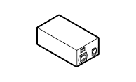
Matrix router frame with rack mounting ears |
IEC power cable 1 |
RS-232 straight serial cable |
Safety and Warranty Info, Quick Start Guide |
Power supply unit(s) 2 |
MX-CPU2 board 3 |
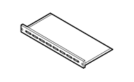
Router input and output board(s) 3 |
48V external PSU for PoE feature 4 |
Mounting power plug with fixing ears (2x) |
Phoenix Combicon 5-pole connector 5 |
|
|
MX-FR9 |
|
|
|
|
|
|
|
|
|
|
|
MX-FR9R |
|
|
|
|
|
|
|
|
|
|
|
MX-FR17 |
|
|
|
|
|
|
|
|
|
|
|
MX-FR17R |
|
|
|
|
|
|
|
|
|
|
|
MX-FR33L |
|
|
|
|
|
|
|
|
|
|
|
MX-FR33R |
|
|
|
|
|
|
|
|
|
|
|
MX-FR65R |
|
|
|
|
|
|
|
|
|
|
|
MX-FR80R |
|
|
|
|
|
|
|
|
|
|


1 The AC plug type depends on the ordered configuration.
2 Supplied with matrix routers with redundant PSU.
3 The supplied board types depend on the ordered configuration.
4 Default accessory for boards with TPS2 ports and PoE-compatible remote power feature.
5 Default accessory for boards with 5-pole Phoenix Analog Audio ports.
1.4. Typical Applications


Integrated System Application and Applying Remote Control Panels
The chapter is about the installation of the device and connecting to other appliances, and also presenting the mounting options.
2.1. Mounting Options
WARNING!For the correct ventilation and to avoid overheating, ensure enough free space around the appliance. Do not cover the appliance, leave the ventilation holes free and never block or bypass the fans.
The front rack ears allow to mount the device as a standard rack unit installation. Use such type (and size) of screw that fits to the rack rails.
The dimensions of the frames can be found in the Mechanical Drawings section.
TIPS AND TRICKS:Pay attention to the rear side of the matrix. Leave enough free space to (un)plug the cables and/or replace an I/O board without moving the matrix!

ATTENTION!Fix the frame to the rack rail using all mounting holes. Choose properly sized screws for mounting. Keep minimum of two threads left after the nut screw.
|
Frame type |
The number of the mounting holes |
|
MX-FR9, MX-FR9R |
2x4 pcs. |
|
MX-FR17, MX-FR17R |
|
|
MX-FR33L, MX-FR33R |
2x6 pcs. |
|
MX-FR65R |
|
|
MX-FR80R |

|
|
Connect the desired Audio/Video/Extender devices to the ports of the I/O ports. Connecting powered off devices is recommended. |
|
|
Connect the desired Controlling devices for local/remote control options. |
|
|
Connect the power cord to the AC power socket and to the matrix. It is recommended to power the devices on as the last step. |


To access the matrix and I/O port settings via Lightware Device Controller software, see the Software Control – Lightware Device Controller Software section.
To access the matrix and I/O port settings by sending Lightware protocol (LW2) commands, see the Programmer’s Reference section.
2.3. Board Installation and Handling
WARNING!The I/O boards and the CPU board are not hot-swappable. The matrix must be powered off before removing/inserting a board.
Important Notices about the Boards
Pay attention to the places of the boards: CPU/input/output boards have different connectors on the motherboard in the matrix, thus they have dedicated slots as indicated in the rear plate. In general:
▪CPU board is always placed in the uppermost position.
▪Output boards are located below the CPU board.
▪Input boards are located in the bottom slots.
Installing a Board
Step 1.Make sure the matrix is powered off.
Step 2.Loosen the fixing screws and remove the blank cover or the previously installed board.

Step 3.Take the board by touching the metal plate only, to prevent ESD-caused problems.

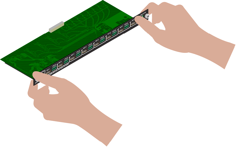
Step 4.Insert the edge of the board in the slot at both sides.

Step 5.Gently push the board in until it stops, then press the plate at the indicated places at once. Thus, the connector of the board and the motherboard will be put together.

Step 6.Tighten the two screws by hand and fix them by a screwdriver with PZ1 head.
INFO:The mute-, lock-, and crosspoint states are stored in the matrix, all other I/O board-related settings are stored by the I/O board series. (An I/O board and its variants with Audio add-on mean the I/O board series.) E.g. if an MX-TPS-IB had been installed previously in a matrix and an MX-TPS-IB-A board was installed later, the previous settings would be applied to the board.
2.4. PSU Installation and Handling
MX-FR80R and MX-FR65R Frames
The PSU of these frames is hot-swappable, thus you do not have to switch off the matrix to replace or install a PSU.
Three slots are available for the FNP-850-12RG PSUs. The load depend on the installed I/O boards, so the best practice for a PSU replacement is to have two PSUs in use continuously. Thus, the third PSU can be replaced safely:
Step 1.Unplug the power cord from the AC socket, then from the desired PSU.
Step 2.Loosen the fixing screw of the PSU by hand and/or a flat-head screwdriver.

#power #redundancy
Step 3.Pull down the lever ( ), then pull out (
 ) the PSU unit by grabbing the screw/lever.

Step 4.To install another PSU: insert the unit in the slot, and push it until it stops.
Step 5.Push up the lever, tighten the locking screw by hand and fix it by a flat-head screwdriver.
Step 6.Plug the power cord to the PSU, then to the AC socket.
MX-FR33R Frame
Two types of PSUs exist for MX-FR33R frames. Both can supply the frame, but the two units are not interchangeable with each other. See more details in the Redundant Power Supplies section.
ATTENTION!The MX-PSU-350 type is hot-swappable, thus you do not have to turn off the matrix to replace a PSU. Former type of PSUs do not support this feature.
The MX-PSU-350 PSU of the MX-FR33R frame can be replaced similarly as the I/O boards, since the PSUs have the same type of fixing screws:
Step 1.Switch off the desired PSU ( ) and unplug the power cord from the AC socket
Step 2.Take out the cord-fixing insert () from the PSU and pull out the power cord.
Step 3.Loosen the fixing screws ( ), then pull out the PSU.
Step 4.Insert the new PSU, push it until it stops.

Step 5.Tighten the two screws by hand and fix them by a screwdriver with PZ1 head.
The following sections are about the physical structure of the device, input/output ports and connectors:
3.1. Hybrid Modular Matrix Concept
Lightware’s hybrid modular matrix routers allow building custom I/O sizes that meet the user’s requirements. Different types of input and output boards give the maximum flexibility for rental and installation signal transmission. The hybrid architecture allows signal routing between boards even if they have different connectors. This way any input can be routed to any one or more outputs if the output interface is capable of transmitting the signal. For example, a DVI source can be routed to an HDMI sink, but HDCP-encrypted sources cannot be routed to non-HDCP capable DVI sinks.
Available interface types include DVI-D single- and dual-link, HDMI, fiber, and twisted pair cables as well.
3.2. Router Frames
Different frame sizes are available from 9x9 up to 80x80. To fit user needs, various input and output interface boards are available that can be mixed in the same frame without limitation.
|
Frame type |
Rack height |
Max. input boards |
Max. input ports |
Max. output boards |
Max. output ports |
|
MX-FR9 |
4U |
1 |
9 |
1 |
9 |
|
MX-FR9R |
4U |
1 |
9 |
1 |
9 |
|
MX-FR17 |
4U |
2 |
17 |
2 |
17 |
|
MX-FR17R |
4U |
2 |
17 |
2 |
17 |
|
MX-FR33L |
6U |
4 |
33 |
4 |
33 |
|
MX-FR33R |
7U |
4 |
33 |
4 |
33 |
|
MX-FR65R |
15U |
8 |
65 |
8 |
65 |
|
MX-FR80R |
15U |
10 |
80 |
10 |
80 |
INFO:The maximum number of input and output ports includes the Test input and Preview output port of the MX-CPU2 processor board.
3.3. I/O Board Configurations
The mute-, lock-, and crosspoint states are stored in the matrix, all other I/O board-related settings are stored by the I/O board series. An I/O board and its variants with Audio add-on mean the I/O board series. E.g. if an MX-TPS-IB had been installed previously in a matrix and an MX-TPS-IB-A board was installed later, the previous settings would be applied to the board.
3.4. MX-CPU2 Processor Board
The CPU board is necessary for the router frame to work. This board is responsible for controlling the matrix and storing the settings.
Test Input and Preview Output Ports
The MX-CPU2 board has a TEST INPUT and a PREVIEW OUTPUT port. Although these ports have special functions, they can be used as normal I/O ports as well. These ports are HDMI and HDCP capable.
MX-FR80R and MX-FR65R
Used in the MX-FR80R (and MX-FR65R) router frame, the Preview output is directly connected to the 80th output port with a DVI splitter. Therefore this port always outputs the same signal as the 80th output (the 8th port of the 10th output board), even if it uses a different interface (TP, OPT, etc.).
The 80th input port of the crosspoint is multiplexed between the Test input port and the 8th port of the 10th input board. This switch is independent from the crosspoint state. The selected port (Test input or Input board #10) will be available as the 80th input on the crosspoint switch.
Other Frames
All other frames use the Test input and Preview output just like any other ports. These ports are referred to as the last port in the crosspoint.
|
Frame Type |
Test Input |
Preview Output |
|
MX-FR9 |
in 9 |
out 9 |
|
MX-FR9R |
in 9 |
out 9 |
|
MX-FR17 |
in 17 |
out 17 |
|
MX-FR17R |
in 17 |
out 17 |
|
MX-FR33L |
in 33 |
out 33 |
|
MX-FR33R |
in 33 |
out 33 |
|
MX-FR65R |
in 80 |
out 80 |
|
MX-FR80R |
multiplexed in 80 |
distributed out 80 |
Other Connectors
The MX-CPU2 board has Ethernet, serial, and alarm ports as well.
MX-FR65R Limitations
The MX-FR65R matrix frame is physically identical to the MX-FR80R. The only difference is a limitation on the number of allowed I/O boards. While the MX-FR80R can work with 10 input and 10 output boards, the MX-FR65R allows only 8.
The frame has 10 physical board slots, but will not boot up when more than 8 input or output boards are inserted. Only the number of the boards is limited, thus they can be used in any of the physical slots. However, to gain exclusive access to the Test input and Preview output ports on the MX-CPU2, it is recommended to leave the last slot empty.
For example, if the input slot #1 is empty, there can be 8 input boards in slots #2 to #9 and the slot #10 left empty. In this case the 65 input ports can be accessed with port numbers 9-72 and 80.
3.4.1. MX-CPU2 Board Features
Lightware MX-CPU2 processor board fits into Lightware hybrid modular matrix routers:
|
Older models |
New models |
|
MX16x16DVI-Pro MX32x32DVI-Pro MX32x32HDMI-Pro MX16x16HDMI-Pro MX32x32DVI-HDCP-Pro MX16x16DVI-HDCP-Pro MX-DVI-FR16 MX-DVI-FR32 MX-DVI-FR32R |
MX-FR9 MX-FR9R MX-FR17 MX-FR17R MX-FR33(L) MX-FR33R MX-FR65R MX-FR80R |
All older models can be updated with the MX-CPU2 processor board.
Changes with MX-CPU2 update
▪Extra I/O ports – Get an additional DVI-HDCP input and output port.
▪Ethernet control – Multiple simultaneous TCP/IP Ethernet connections.
▪Combine HDCP and non-HDCP boards – Any interface board combination is possible in the same frame.
3.5. Input Boards
Several input interface boards are available. Each model has different capabilities and functions. Below table shows a summary of the main features.
|
Model |
Default connectors |
Optional connectors |
HDMI Capability |
HDCP Capability |
EDID Emulation |
Cable EQ |
|
MX-DVID-IB |
8x DVI-I (D) 1 |
- |
- |
- |
|
|
|
MX-DVI-4K-IB |
8x DVI-I (D) 1 |
- |
|
|
|
|
|
MX-DVI-TP-IB |
8x RJ45 |
- |
- |
- |
- |
ü |
|
MX-DVI-TP-IB+ |
8x RJ45 double |
- |
- |
- |
|
|
|
MX-DVI-OPT-IB-… |
8x optical |
- |
- |
- |
- |
- |
|
MX-DVIDL-IB |
4x DVI-I (D) (dual link) |
- |
- |
- |
|
|
|
MX-DVIDL-OPT-IB-… |
4x optical (dual link) |
- |
- |
- |
- |
- |
|
MX-DVI-HDCP-IB |
8x DVI-I (D) 1 |
- |
|
|
|
|
|
MX-DVII-HDCP-IB |
8x DVI-I |
- |
|
|
|
|
|
MXD-UMX-IB |
8x DVI-I |
Phoenix, S/PDIF |
|
|
|
|
|
MX-HDMI-IB |
8x HDMI |
- |
|
|
|
|
|
MX-HDMI-TP-IB |
8x RJ45 double |
- |
|
|
|
|
|
MXD-HDMI-TP-IB |
8x RJ45 double |
RS-232, S/PDIF |
|
|
|
|
|
MX-HDMI-OPT-IB-… |
8x optical |
- |
|
|
- |
- |
|
MX-3GSDI-IB |
8x BNC, S/PDIF |
- |
|
- |
- |
|
|
MX-CPU2 Test Input |
1x DVI-I (D) 1 |
- |
|
|
|
- |
|
MX-TPS-IB, -A, -S |
8x TPS |
Phoenix, S/PDIF |
|
|
|
|
|
MX-HDMI-3D-IB, -A, -S |
8x HDMI |
Phoenix, S/PDIF |
|
|
|
|
|
MX-TPS2-IB-P, -AP, -SP |
8x TPS |
Phoenix, S/PDIF |
|
|
|
|
|
MX-4TPS2-4HDMI-IB, -A,- S |
4x TPS, 4x HDMI |
Phoenix, S/PDIF |
|
|
|
|
|
MX-4TPS2-4HDMI-IB-P, -AP, -SP |
4x TPS 4, 4x HDMI |
Phoenix, S/PDIF |
|
|
|
|

1 Any DVI connector can be plugged in, but only digital pins are connected.
2 Limited cable equalization. See details in the specifications.
3 Cable EQ by HDBaseTTM on the TPS ports.
4 With PoE-compatible (Power over Ethernet) remote power feature.
3.6. Output Boards
Several output interface boards are available. Each model has different capabilities and functions. The table below shows a summary of the main features.
|
Model |
Deafult connectors |
Optional Connectors |
HDMI Capability |
HDCP Capability |
EDID Reading |
Re-clocking |
|
MX-DVID-OB |
8x DVI-I (D) 1 |
- |
- |
- |
|
|
|
MX-DVI-4K-OB |
8x DVI-I (D) 1 |
- |
|
|
|
|
|
MX-DVI-TP-OB |
8x RJ45 |
- |
- |
- |
- |
|
|
MX-DVI-TP-OB+ |
8x RJ45 double |
- |
- |
- |
|
|
|
MX-DVI-OPT-OB-… |
8x optical |
- |
- |
- |
- |
- |
|
MX-DVIDL-OPT-OB... |
4x optical (dual link) |
- |
- |
- |
- |
- |
|
MX-DVI-OPT-OB-R-… |
8x optical |
- |
- |
- |
- |
|
|
MX-DVIDL-OB |
4x DVI-I (D) (dual link) 1 |
- |
- |
- |
|
|
|
MX-DVI-HDCP-OB |
8x DVI-I (D) 1 |
- |
|
|
|
|
|
MX-HDMI-OB |
8x HDMI, S/PDIF |
- |
|
|
|
|
|
MX-HDMI-TP-OB |
8x RJ45 double |
- |
|
|
|
|
|
MXD-HDMI-TP-OB |
8x RJ45 double |
RS-232, S/PDIF |
|
|
|
|
|
MX-HDMI-OPT-OB-… |
8x optical |
- |
|
|
|
- |
|
MX-CPU2 Preview Out |
1x DVI-I (D) 1 |
- |
|
|
|
|
|
MX-HDMI-3D-OB, -A, -S |
8x HDMI |
Phoenix, S/PDIF |
|
|
|
|
|
MX-HDMI-OPT-OB-R-… |
8x optical |
- |
|
|
|
|
|
MX-TPS-OB, -A, -S |
8x TPS |
Phoenix, S/PDIF |
|
|
|
|
|
MX-TPS2-OB-P, -AP, -SP |
8x TPS 2 |
Phoenix, S/PDIF |
|
|
|
|
|
MX-AUDIO-OB-A |
8x Phoenix |
- |
|
|
|
|
|
MX-4TPS2-4HDMI-OB, -A, -S |
4x TPS, 4x HDMI |
Phoenix, S/PDIF |
|
|
|
|
|
MX-4TPS-4HDMI-OB-P, -AP, -SP |
4x TPS, 4x HDMI |
Phoenix, S/PDIF |
|
|
|
|

1 Any DVI connector can be plugged in, but only digital pins are connected.
2 With PoE-compatible remote power feature.
WARNING!Please make sure that all slots contain a board or a blank plate during usage (MX-BLANK-IO, part no: 52400115).
3.7. MX-FR80R and MX-FR65R
Front View

|
|
Menu display |
Displays status information and menu operation. |
|
|
Menu navigation |
Up, down, left, right, escape, and enter buttons for menu navigation. |
|
|
Status LEDs |
CPU live LED blinks to indicate normal operation. Power LED shines green when the router is powered on. |
|
|
USB control |
USB connection for Lightware Device Controller Software. |
|
|
Take / Auto |
Displays the current switching mode of the router (TAKE or AUTOTAKE). Long press toggles the switching mode, short press executes switching in TAKE mode. |
|
|
Preset buttons |
Load preset: apply a previously saved crosspoint preset from one of the preset memories. Save preset: stores current crosspoint state in one of the preset memories. |
|
|
Signal present |
Displays live sources and attached sinks on source and destination buttons. |
|
|
EDID mode |
Switches the Menu display to EDID menu allowing EDID switch, EDID save etc. |
|
|
Control lock |
Disables or enables front panel operation. When it shines red, all operations on the front panel are prohibited. |
|
|
Output lock |
Locks and protects one (or more) outputs. Inhibits accidental input changing on the protected output. |
|
|
Source buttons |
Source buttons have three functions: to select an input, to select a preset and to view the selected input’s state (only in TAKE mode). |
|
|
Destination buttons |
Destination buttons have two functions: to select an output, or to view the selected output’s state. |


ATTENTION!In the case of the MX-FR65R matrix the attached label can be seen on the front panel.

INFO:The unlabeled buttons are disabled, and reserved for future developments.
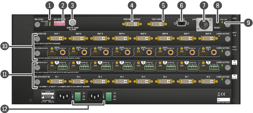
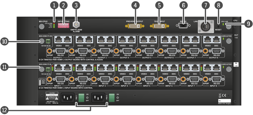
Rear View

|
|
Status LEDs |
LED indicators for internal DC power voltages and alarm. |
|
|
DIP settings |
Special settings can be made with these switches. |
|
|
Alarm out |
Standard SMPTE 269M alarm output with BNC connector. See the Alarm Output section for more information. |
|
|
Preview output |
DVI output connector that is directly connected to the 80th output. See the DVI Inputs and Outputs and the Test Input and Preview Output sections for more information. |
|
|
Test input |
DVI input connector, which can be configured as an alternative for the 80th input. See the DVI Inputs and Outputs and the Test Input and Preview Output sections. |
|
|
Serial port |
9-pole D-SUB female connector for RS-232 serial connection. See the RS-232 Ports section for more information. |
|
|
Ethernet port |
Locking RJ45 connector. Remote control port for connecting the unit to Local Area Network (LAN) and firmware update can be also performed over this interface. See the Ethernet Ports section for more information. |
|
|
Reset button |
Reset button; reboots the matrix. It has the same result as disconnecting the device from the power source and reconnecting it again. |
|
|
CPU live |
CPU live LED blinks to indicate normal operation. |
|
|
Input boards |
Modular input board slots. Connect source devices to these connectors. |
|
|
Output boards |
Modular output board slots. Connect sink devices to these connectors. |
|
|
Power supplies |
Hot swap slots for power supply units. See the Powering on section for more information. |
INFO:The MX-FR65R is shipped with 2 power supply units and the rightmost PSU slot is covered with a blank metal plate.
INFO:The MX-FR65R has a label showing that maximum 8 input and output boards are allowed.

3.8. MX-FR33R
Front View

|
|
USB control |
USB connection for Lightware Device Controller software. |
|
|
Menu display |
Displays status information and menu operation. |
|
|
Menu navigation |
Arrows, escape, and enter buttons for menu navigation. |
|
|
Status LEDs |
CPU live LED blinks to indicate normal operation. Power LED shines green when the router is powered on. |
|
|
Control lock |
Press long to disable or enable front panel buttons. When it shines red, all operations on front panel are prohibited. |
|
|
Output lock |
Locks one (or more) outputs. Inhibits accidental input changing on the protected output. |
|
|
Source buttons |
Source buttons can be used to select an input or preset or to view the selected input’s state. |
|
|
Destination buttons |
Destination buttons can be used to select an output, or view the selected output’s state. |
|
|
Take / Auto |
Displays the current switching mode (TAKE or AUTOTAKE). Long press toggles the switching mode, short press executes switching in TAKE mode. |
|
|
Preset buttons |
Load preset: apply a previously saved crosspoint preset from one of the preset memories. Save preset: stores current crosspoint state in one of the preset memories. |
|
|
EDID mode |
Switches the Menu display to EDID menu allowing EDID switch, EDID save etc. |
|
|
Signal present |
Displays live sources and attached sinks on source and destination buttons. |
Rear View

|
|
Status LEDs |
LED indicators for internal DC power voltages and alarm. |
|
|
DIP settings |
Special settings can be made with these switches. |
|
|
Alarm out |
Standard SMPTE 269M alarm output with BNC connector. See the Alarm Output section for more information. |
|
|
Preview output |
DVI output connector that is directly connected to the 33rd output. See the DVI Inputs and Outputs and the Test Input and Preview Output sections for more information. |
|
|
Test input |
DVI input connector, which can be configured as an alternative for the 33rd input. See the DVI Inputs and Outputs and the Test Input and Preview Output sections. |
|
|
Serial port |
9 pole D-SUB female connector for RS-232 serial connection. See the RS-232 Ports section for more information. |
|
|
Ethernet port |
Locking RJ45 connector. Remote control port for connecting the unit to Local Area Network (LAN) and firmware update can be also performed over this interface. See the Ethernet Ports section for more information. |
|
|
Reset button |
Reset button; reboots the matrix. It has the same result as disconnecting the device from the power source and reconnecting it again. |
|
|
CPU live |
CPU live LED blinks to indicate normal operation. |
|
|
Output boards |
Modular output board slots. Connect sink devices to these connectors. |
|
|
Input boards |
Modular input board slots. Connect source devices to these connectors. |
|
|
Power supplies |
Hot swap slots for power supply units. See the Powering on section for more information. |
3.9. MX-FR33L
Front View

|
|
USB control |
USB connection for Lightware Device Controller software. |
|
|
Menu display |
Displays status information and menu operation. |
|
|
Menu navigation |
Arrows, escape, and enter buttons for menu navigation. |
|
|
Status LEDs |
CPU live LED blinks to indicate normal operation. Power LED shines green when the router is powered on. |
|
|
Control lock |
Press long to disable or enable front panel buttons. When it shines red, all operations on front panel are prohibited. |
|
|
Output lock |
Locks one (or more) outputs. Inhibits accidental input changing on the protected output. |
|
|
Source buttons |
Source buttons can be used to select an input or preset or to view the selected input’s state. |
|
|
Destination buttons |
Destination buttons can be used to select an output, or view the selected output’s state. |
|
|
Take / Auto |
Displays the current switching mode (TAKE or AUTOTAKE). Long press toggles the switching mode, short press executes switching in TAKE mode. |
|
|
Preset buttons |
Load preset: apply a previously saved crosspoint preset from one of the preset memories. Save preset: stores current crosspoint state in one of the preset memories. |
|
|
EDID mode |
Switches the Menu display to EDID menu allowing EDID switch, EDID save etc. |
|
|
Signal present |
Displays live sources and attached sinks on source and destination buttons. |
Rear View

|
|
Status LEDs |
LED indicators for internal DC power voltages and alarm. |
|
|
DIP settings |
Special settings can be made with these switches. |
|
|
Alarm out |
Standard SMPTE 269M alarm output with BNC connector. See the Alarm Output section for more information. |
|
|
Preview output |
DVI output connector, that is directly connected to the 33rd output. See the DVI Inputs and Outputs and the Test Input and Preview Output sections for more information. |
|
|
Test input |
DVI input connector which can be configured as an alternative for the 33rd input. See the DVI Inputs and Outputs and the Test Input and Preview Output sections. |
|
|
Serial port |
9 pole D-SUB female connector for RS-232 serial connection. See the RS-232 Ports section for more information. |
|
|
Ethernet port |
Locking RJ45 connector. Remote control port for connecting the unit to Local Area Network (LAN) and firmware update can be also performed over this interface. See the Ethernet Ports section for more information. |
|
|
Reset button |
Reset button; reboots the matrix. It has the same result as disconnecting the device from the power source and reconnecting it again. |
|
|
CPU live |
CPU live LED blinks to indicate normal operation. |
|
|
Output boards |
Modular output board slots. Connect sink devices to these connectors. |
|
|
Main switch |
|
|
|
Input boards |
Modular input board slots. Connect source devices to these connectors. |
|
|
Power |
AC power connector. |

3.10. MX-FR17
Front View

|
|
USB control |
USB connection for Lightware Device Controller software. |
|
|
Menu display |
Displays status information and menu operation. |
|
|
Menu navigation |
Arrows, escape, and enter buttons for menu navigation. |
|
|
Status LEDs |
CPU live LED blinks to indicate normal operation. Power LED shines green when the router is powered on. |
|
|
Control lock |
Press long to disable or enable front panel buttons. When it shines red, all operations on the front panel are prohibited. |
|
|
Output lock |
Locks one (or more) outputs. Inhibits accidental input changing on the protected output. |
|
|
Source buttons |
Select an input or preset or to view the selected input’s state. |
|
|
Destination buttons |
Destination buttons can be used to select an output, or view the selected output’s state. |
|
|
Take / Auto |
Displays the current switching mode (TAKE or AUTOTAKE). Long press toggles the switching mode, short press executes switching in TAKE mode. |
|
|
Preset buttons |
Load preset: apply a previously saved crosspoint preset from one of the preset memories. Save preset: stores current crosspoint state in one of the preset memories. |
|
|
EDID mode |
Switches the Menu display to EDID menu allowing EDID switch, EDID save etc. |
|
|
Signal present |
Displays live sources and attached sinks on source and destination buttons. |
Rear View

|
|
Status LEDs |
LED indicators for internal DC power voltages and alarm. |
|
|
DIP settings |
Special settings can be made with these switches. |
|
|
Alarm out |
Standard SMPTE 269M alarm output with BNC connector. See the Alarm Output section for more information. |
|
|
Preview output |
DVI output connector that is directly connected to the 17th output. See the DVI Inputs and Outputs and the Test Input and Preview Output sections for more information. |
|
|
Test input |
DVI input connector, which can be configured as an alternative for the 17th input. See the DVI Inputs and Outputs and the Test Input and Preview Output sections. |
|
|
Serial port |
9 pole D-SUB female connector for RS-232 serial connection. See the RS-232 Ports section for more information. |
|
|
Ethernet port |
Locking RJ45 connector. Remote control port for connecting the unit to Local Area Network (LAN) and for firmware update. See the Ethernet Ports section for more information. |
|
|
Reset button |
Reset button; reboots the matrix. It has the same result as disconnecting the device from the power source and reconnecting it again. |
|
|
CPU live |
CPU live LED blinks to indicate normal operation. |
|
|
Output boards |
Modular output board slots. Connect sink devices to these connectors. |
|
|
Input boards |
Modular input board slots. Connect source devices to these connectors. |
|
|
Power |
Mains switch and AC power connector. |

3.11. MX-FR17R
Front View

|
|
USB control |
USB connection for Lightware Device Controller software. |
|
|
Menu display |
Displays status information and menu operation. |
|
|
Menu navigation |
Arrows, escape, and enter buttons for menu navigation. |
|
|
Status LEDs |
CPU live LED blinks to indicate normal operation. Power LED shines green when the router is powered on. |
|
|
Control lock |
Press long to disable or enable front panel buttons. When it shines red, all operations on the front panel are prohibited. |
|
|
Output lock |
Locks one (or more) outputs. Inhibits accidental input changing on the protected output. |
|
|
Source buttons |
Select an input or preset or to view the selected input’s state. |
|
|
Destination buttons |
Destination buttons can be used to select an output, or view the selected output’s state. |
|
|
Take / Auto |
Displays the current switching mode (TAKE or AUTOTAKE). Long press toggles the switching mode, short press executes switching in TAKE mode. |
|
|
Preset buttons |
Load preset: apply a previously saved crosspoint preset from one of the preset memories. Save preset: stores current crosspoint state in one of the preset memories. |
|
|
EDID mode |
Switches the Menu display to EDID menu allowing EDID switch, EDID save etc. |
|
|
Signal present |
Displays live sources and attached sinks on source and destination buttons. |
Rear View
|
|
Status LEDs |
LED indicators for internal DC power voltages and alarm. |
|
|
DIP settings |
Special settings can be made with these switches. |
|
|
Alarm out |
Standard SMPTE 269M alarm output with BNC connector. See the Alarm Output section for more information. |
|
|
Preview output |
DVI output connector that is directly connected to the 17th output. See the DVI Inputs and Outputs and the Test Input and Preview Output sections for more information. |
|
|
Test input |
DVI input connector, which can be configured as an alternative for the 17th input. See the DVI Inputs and Outputs and the Test Input and Preview Output sections. |
|
|
Serial port |
9 pole D-SUB female connector for RS-232 serial connection. See the RS-232 Ports section for more information. |
|
|
Ethernet port |
Locking RJ45 connector. Remote control port for connecting the unit to Local Area Network (LAN) and for firmware update. See the Ethernet Ports section for more information. |
|
|
Reset button |
Reset button; reboots the matrix. It has the same result as disconnecting the device from the power source and reconnecting it again. |
|
|
CPU live |
CPU live LED blinks to indicate normal operation. |
|
|
Output boards |
Modular output board slots. Connect sink devices to these connectors. |
|
|
Input boards |
Modular input board slots. Connect source devices to these connectors. |
|
|
Power |
Mains switch and AC power connector of the redundant power supplies. |
3.12. MX-FR9
Front View

|
|
USB control |
USB connection for Lightware Device Controller software. |
|
|
Menu display |
Displays status information and menu operation. |
|
|
Menu navigation |
Arrows, escape, and enter buttons for menu navigation. |
|
|
Status LEDs |
CPU live LED blinks to indicate normal operation. Power LED shines green when the router is powered on. |
|
|
Control lock |
Press long to disable or enable front panel buttons. When it shines red, all operations on front panel are prohibited. |
|
|
Output lock |
Locks one (or more) outputs. Inhibits accidental input changing on protected output. |
|
|
Source buttons |
Select an input or preset or to view the selected input’s state. |
|
|
Destination buttons |
Destination buttons can be used to select an output, or view the selected output’s state. |
|
|
Take / Auto |
Displays the current switching mode (TAKE or AUTOTAKE). Long press toggles the switching mode, short press executes switching in TAKE mode. |
|
|
Preset buttons |
Load preset: apply a previously saved crosspoint preset from one of the preset memories. Save preset: stores the current crosspoint state in one of the preset memories. |
|
|
EDID mode |
Switches the Menu display to EDID menu allowing EDID switch, EDID save etc. |
|
|
Signal present |
Displays live sources and attached sinks on source and destination buttons. |

|
|
Status LEDs |
LED indicators for internal DC power voltages and alarm. |
|
|
DIP settings |
Special settings can be made with these switches. |
|
|
Alarm out |
Standard SMPTE 269M alarm output with BNC connector. See the Alarm Output section for more information. |
|
|
Preview output |
DVI output connector that is directly connected to the 9th output. See the DVI Inputs and Outputs and the Test Input and Preview Output sections for more information. |
|
|
Test input |
DVI input connector, which can be configured as an alternative for the 9th input. See the DVI Inputs and Outputs and the Test Input and Preview Output sections. |
|
|
Serial port |
9 pole D-SUB female connector for RS-232 serial connection. See the RS-232 Ports section for more information. |
|
|
Ethernet port |
Locking RJ45 connector. Remote control port for connecting the unit to Local Area Network (LAN) and firmware update can be also performed over this interface. See the Ethernet Ports section for more information. |
|
|
Reset button |
Reset button; reboots the matrix. It has the same result as disconnecting the device from the power source and reconnecting it again. |
|
|
CPU live |
CPU live LED blinks to indicate normal operation. |
|
|
Output boards |
Modular output board slots. Connect sink devices to these connectors. |
|
|
Input boards |
Modular input board slots. Connect source devices to these connectors. |
|
|
Power |
Mains switch and AC power connector. |
3.13. MX-FR9R
Front View

|
|
USB control |
USB connection for Lightware Device Controller software. |
|
|
Menu display |
Displays status information and menu operation. |
|
|
Menu navigation |
Arrows, escape, and enter buttons for menu navigation. |
|
|
Status LEDs |
CPU live LED blinks to indicate normal operation. Power LED shines green when the router is powered on. |
|
|
Control lock |
Press long to disable or enable front panel buttons. When it shines red, all operations on front panel are prohibited. |
|
|
Output lock |
Locks one (or more) outputs. Inhibits accidental input changing on the protected output. |
|
|
Source buttons |
Select an input or preset or to view the selected input’s state. |
|
|
Destination buttons |
Destination buttons can be used to select an output, or view the selected output’s state. |
|
|
Take / Auto |
Displays the current switching mode (TAKE or AUTOTAKE). Long press toggles the switching mode, short press executes switching in TAKE mode. |
|
|
Preset buttons |
Load preset: apply a previously saved crosspoint preset from one of the preset memories. Save preset: stores the current crosspoint state in one of the preset memories. |
|
|
EDID mode |
Switches the Menu display to EDID menu allowing EDID switch, EDID save etc. |
|
|
Signal present |
Displays live sources and attached sinks on source and destination buttons. |
Rear View
|
|
Status LEDs |
LED indicators for internal DC power voltages and alarm. |
|
|
DIP settings |
Special settings can be made with these switches. |
|
|
Alarm out |
Standard SMPTE 269M alarm output with BNC connector. See the Alarm Output section for more information. |
|
|
Preview output |
DVI output connector that is directly connected to the 9th output. See the DVI Inputs and Outputs and the Test Input and Preview Output sections for more information. |
|
|
Test input |
DVI input connector, which can be configured as an alternative for the 9th input. See the DVI Inputs and Outputs and the Test Input and Preview Output sections. |
|
|
Serial port |
9 pole D-SUB female connector for RS-232 serial connection. See the RS-232 Ports section for more information. |
|
|
Ethernet port |
Locking RJ45 connector. Remote control port for connecting the unit to Local Area Network (LAN) and firmware update can be also performed over this interface. See the Ethernet Ports section for more information. |
|
|
Reset button |
Reset button; reboots the matrix. It has the same result as disconnecting the device from the power source and reconnecting it again. |
|
|
CPU live |
CPU live LED blinks to indicate normal operation. |
|
|
Output boards |
Modular output board slots. Connect sink devices to these connectors. |
|
|
Input boards |
Modular input board slots. Connect source devices to these connectors. |
|
|
Power |
Mains switch and AC power connector of the redundant power supplies. |
3.14. Electrical Connections
The sections below describe all possible electrical connections of a hybrid router. Please note that the availability of some connection types depend on your modular configuration, as different boards have different connectors.
3.14.1. Power Connections
Mains Power

Certain frames have redundant power supplies. Every PSU has its own standard IEC power connector and works with 100 to 240 Volts AC, 50 Hz or 60 Hz power source. See the Powering on section for more information. #power #redundancy
|
Frame type |
PSU location |
Number of PSUs |
Output/PSU (max) |
|
MX-FR9 |
built-in |
1 |
160W |
|
MX-FR9R |
built-in |
2 |
350W |
|
MX-FR17 |
built-in |
1 |
160W |
|
MX-FR17R |
built-in |
2 |
350W |
|
MX-FR33L |
built-in |
1 |
250W |
|
MX-FR33R |
hot swappable |
2 |
160W |
|
MX-FR65R |
hot swappable |
3 |
850W |
|
MX-FR80R |
hot swappable |
3 |
850W |
DC IN Connector for TPS Boards
A 2-pole Phoenix connector is used for 12V DC input for TP and TPS boards and 48V for TPS2 boards. External power adaptor is needed when I/O boards power TP or TPS extenders remotely.

WARNING!Use only power adaptors taken from Lightware. Warranty void if damage occurs due to use of a different power source.
Compatible Plug Type
Phoenix® Combicon series (3.5mm pitch), type: MC 1.5/2-ST-3.5.
3.14.2. Video Inputs and Outputs

29 pole DVI-I connectors, however, internally connected pins vary by input board type. This way, users can plug in any DVI connector, but keep in mind that analog signals (such as VGA or RGBHV) are processed only on certain boards.
INFO:Always use high quality DVI cables for connecting sources and displays.
29 pole DVI-I connectors for outputs only have digital pins internally connected. This way, users can plug in any DVI connector, but keep in mind that analog signals (such as VGA or RGBHV) are NOT available on outputs.
Fiber Cable Powering
DVI outputs are able to supply 500 mA current on DDC +5V output (pin 14 on output connectors) which is sufficient to supply power to hybrid fiber optical DVI cables. Standard DVI outputs usually supply only 55 mA current on +5V output, thus are unable to directly power a fiber optical cable.
INFO:The matrix router does not check if the connected sink (monitor, projector or other equipment) supports Hotplug or EDID signals, but outputs the selected signal immediately after switch command.
HDMI Inputs and Outputs

Boards with HDMI ports provide standard 19-pole HDMI connectors for inputs and outputs. Always use high quality HDMI cables for connecting sources and displays.
3.14.3. Audio Inputs and Outputs
S/PDIF Digital Audio Input and Output

Certain interface boards have standard RCA receptacles for digital coaxial audio inputs and outputs.
ATTENTION!Plugs and sockets on consumer equipment are conventionally color-coded by CEA/CEDIA-863-B (ANSI) to aid correct connections. According to the standard Lightware uses orange colored RCA connectors for S/PDIF signals.
Analog Stereo Audio Input and Output

Certain interface boards have standard RCA receptacles for analog stereo audio inputs and outputs. Inputs and outputs work with standard line-in and line-out voltage levels.
ATTENTION!Plugs and sockets on consumer equipment are conventionally color-coded by CEA/CEDIA-863-B (ANSI) to aid correct connections. According to the standard Lightware uses red colored RCA connectors for the right channel of analog stereo audio signals and white colored RCA connectors for the left channel of analog stereo audio signals.
Symmetrical Analog Stereo Audio
A 5-pole Phoenix connector is used for balanced analog audio (line in/out). Some I/O boards use this connector as a configurable input or output. Always check if this connector is configured as an output or input to prevent connecting two outputs together.

Unbalanced audio signals can be connected as well. For asymmetrical output, connect only + and ground. For asymmetrical input, connect + and ground to the source and connect – to the ground.
Compatible Plug Type
Phoenix® Combicon series (3.5mm pitch), type: MC 1.5/5-ST-3.5, order number: 1840395.
Please see the short guide about the audio cable wiring in the Cable Wiring Guide section.
3.14.4. RJ45 Connectors and Twisted Pair Cables
The Wiring of Twisted Pair Cables
Lightware recommends the termination of TP cables on the basis of TIA/EIA T 568 A or TIA/EIA T 568 B standards.

MX-TP Input and Output Ports
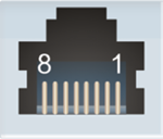
HDMI-TP and DVI-TP interface boards provide standard RJ-45 connectors for VIDEO IN / OUT and DDC IN / OUT. Please note that the DDC connector is not available on the MX-DVI-TP-IB and MX-DVI-TP-OB, but available on the MX-DVI-TP-IB+ and MX-DVI-TP-OB+ boards.
|
Pin |
VIDEO IN/OUT |
DDC IN |
DDC OUT |
|
1 |
TMDS Data0+ |
CEC (no conn.) |
CEC (no conn.) |
|
2 |
TMDS Data0- |
Hot Plug Detect (in) |
Hot Plug Detect (out) |
|
3 |
TMDS Clock+ |
RS-232 RX |
RS-232 RX |
|
4 |
TMDS Data1+ |
DDC CLK |
DDC CLK |
|
5 |
TMDS Data1- |
+12V (out) |
+12V (out) |
|
6 |
TMDS Clock- |
RS-232 TX |
RS-232 TX |
|
7 |
TMDS Data2+ |
DDC SDA |
DDC SDA |
|
8 |
TMDS Data2- |
GND |
GND |
MX-TPS, MX-TPS2 Inputs and Outputs

MX-TPS boards provide standard RJ-45 connectors for TPS extenders or MX boards.
ATTENTION!The same RJ-45 connector is used for Ethernet. Avoid connecting LAN cables to the TPS connectors. If the port of the TPS board was set to AUTO mode, it is able to recognize the LAN cable and swap to Ethernet fallback mode automatically. In this case, the port works as an Ethernet switch, but a TPS CAT cable is not allowed to be connected to the Ethernet port.
|
LED1, Amber |
LED2, Green |
|
|
OFF |
Remote power is disabled |
No TPS link |
|
Blinking |
N/A |
Low power mode, |
|
Blinking |
N/A |
Low power mode, |
|
Blinking |
N/A |
Ethernet fallback mode |
|
ON |
Remote power is enabled |
TPS link is active |


Lightware matrix routers can be remote controlled through Ethernet as well. The Ethernet port can be connected to a LAN hub, switch or router with a UTP patch cable. If connecting to a computer directly, a cross UTP cable has to be used! The robust Neutrik EtherCON connector ensures reliable connection, however, normal RJ45 connectors can be used as well.
ATTENTION!TPS link uses the same RJ45 connector but a TPS CAT cable is not allowed to be connected to the Ethernet connector! It seriously damages both devices.
TPS and TPS2 I/O Boards
The MX-TPS and MX-TPS2 I/O boards also have Ethernet up-link connectors. It is an RJ45 receptacle with two LEDs and it has the same pin connection as the Neutrik EtherCON.

MXD-HDMI-TP interface boards provide standard 9-pin female and male D-sub receptacles for serial port pass-through to remote HDMI-TP extenders. The MX-CPU2 boards also contain an RS-232 port, which allows to remote control the matrix via industry standard 9-pole D-sub female connector.

ATTENTION!The pinouts of the two connectors are different, which is highlighted in table below.
#rs-232 #rs232 #serial
BNC output connector for SMPTE 269M alarm signaling. The router handles different error levels. Only the three highest level errors trigger the alarm output and the CPU alarm LED, see more information in the Error Handling section.

3.15. Input Boards

MX-DVID-IB

MX-DVI-4K-IB

MX-DVI-TP-IB

MX-DVI-TP-IB+

MX-DVI-OPT-IB-LC

MX-DVI-OPT-IB-ST

MX-DVIDL-IB

MX-DVIDL-OPT-IB-LC

MX-DVIDL-OPT-IB-NT

MX-DVIDL-OPT-IB-SC

MX-DVI-HDCP-IB

MX-DVII-HDCP-IB

MXD-UMX-IB

MX-HDMI-IB

MX-HDMI-TP-IB

MXD-HDMI-TP-IB

MX-HDMI-OPT-IB-LC

MX-HDMI-OPT-IB-NT

MX-HDMI-OPT-IB-SC

MX-3GSDI-IB

MX-TPS-IB

MX-TPS-IB-A

MX-TPS-IB-S

MX-HDMI-3D-IB

MX-HDMI-3D-IB-A

MX-HDMI-3D-IB-S

MX-TPS2-IB-P

MX-TPS2-IB-AP

MX-TPS2-IB-SP

MX-4TPS2-4HDMI-IB

MX-4TPS2-4HDMI-IB-A

MX-4TPS2-4HDMI-IB-S

MX-4TPS2-4HDMI-IB-P

MX-4TPS2-4HDMI-IB-AP

MX-4TPS2-4HDMI-IB-SP
3.16. Output Boards

MX-DVID-OB

MX-DVI-4K-OB

MX-DVI-TP-OB

MX-DVI-TP-OB+

MX-DVI-OPT-OB-LC

MX-DVI-OPT-OB-SC

MX-DVI-OPT-OB-ST

MX-DVI-OPT-OB-R-LC

MX-DVI-OPT-OB-R-NT

MX-DVI-OPT-OB-R-SC

MX-DVI-OPT-OB-R-ST

MX-DVIDL-OPT-OB-LC

MX-DVIDL-OPT-OB-NT

MX-DVIDL-OB

MX-DVI-HDCP-OB

MX-HDMI-OB

MX-HDMI-TP-OB

MXD-HDMI-TP-OB

MX-HDMI-OPT-OB-LC

MX-HDMI-OPT-OB-NT

MX-HDMI-OPT-OB-SC

MX-HDMI-3D-OB

MX-HDMI-3D-OB-A

MX-HDMI-3D-OB-S

MX-HDMI-OPT-OB-R-LC

MX-HDMI-OPT-OB-R-NT

MX-HDMI-OPT-OB-R-SC

MX-TPS-OB

MX-TPS-OB-A

MX-TPS-OB-S

MX-TPS2-OB-P

MX-TPS2-OB-AP

MX-TPS2-OB-SP

MX-AUDIO-OB-A

MX-4TPS2-4HDMI-OB

MX-4TPS2-4HDMI-OB-A

MX-4TPS2-4HDMI-OB-S

MX-4TPS2-4HDMI-OB-P

MX-4TPS2-4HDMI-OB-AP

MX-4TPS2-4HDMI-OB-SP
This chapter is about the powering and operating of the device, describing the functions that are available by the front/rear controls:
Connect the power cords to the power supply units’ IEC standard power input connector. After switching the mains switch to the ‘I’ position, the router starts up. If the mains switch is not available or it was in the ‘I’ position, then the matrix starts up immediately when the power cord is connected to the AC source.
During the initial self-test and loading of the latest settings "Booting…" appears on the LCD screen. After the self-test, the router reloads its last configuration and it is ready to use. In the case of a hardware failure, an error message is displayed.
INFO:After switching ON, the router reloads the latest settings that were used before it was turned off. The router has an internal emergency memory that stores all current settings and configurations. This memory is independent from presets and invisible for the user. This built-in feature helps the system to be ready immediately in the case of a power failure or accidental power down.
4.1.1. Redundant Power Supplies
MX-FR9R and MX-FR17R
These models contain two internal PSUs, which are hot swappable, but not replacable. If any problem occurs with a PSU, the other unit can supply the frame.

Replacable Redundant PSU Types
The MX-FR33R, MX-FR65R and MX-FR80R frames have hot pluggable, redundant power supplies. Power supply units (PSU) can be dismounted or installed during operation. Depending on the router’s configuration (number and type of I/O boards) one or two PSUs are needed to operate. The extra PSU makes the system redundant. Please consult Lightware support about your system configuration to ensure redundancy.
If more than one PSU is needed for supplying the matrix, please make sure that the second PSU gets power no more than 10 seconds after the first one is plugged in to prevent overload on the first PSU.
If one PSU is enough to supply the whole matrix, then the other one(s) can be left unplugged.
INFO:The type of the PSU in the MX-FR33R frame is MX-PSU-350 while the PSU in the MX-FR65R and MX-FR80R frames is FNP850-12RG.
The following redundant Power Supply Units are available in the matrix frames:
PSU for MX-FR33R
Two types of PSUs exist for MX-FR33R frames. Both can supply the frame, but the two units are not interchangeable with each other.

PSU-160 (phased out product)

MX-PSU-350 (available for order)
WARNING!Pay attention to install the same type of PSUs in a matrix!
PSU for MX-FR80R and MX-FR65R

FNP850-12RG
#power #redundancy
4.2. The Remote Power Feature of MX-TPS Boards
WARNING!Incorrect configuration may cause damage to the devices. Do to connect TPS-TX/RX90 extenders to the TPS boards, as the devices will be damaged.
MX-TPS boards can be configured to remotely power the connected TPS-TX/RX95 or TX/RX96 extenders. The following boards support this feature:
▪MX-TPS-IB, -A, -S
▪MX-TPS-OB, -A, -S
To use remote powering, you will need the following:
▪PSU-12VP (part no: 91340007) external PSU,
▪Jumper pack (part no: 91340008).

Important instructions
▪When remote power is activethe ports are NOT HDBaseT™ compliant, in this case do not connect any third party devices.
▪The jumper setting below is compatible only with Lightware TPS-TX/RX95 and TPS-TX/RX96 devices.
Cable length
Please note that the distances are 20% shorter if the remote powering is used in the case of AWG 26 CAT cables. The remote powering can be enabled or disabled for each port separately. Some of the ports can have remote powering enabled for Lightware extenders, while other ports can have remote powering disabled and be used with HDBaseT™ compliant devices.
Settings in the TPS Board
Place the jumper block to the indicated position in the board at all desired TPS ports:

Setting in the Extender
When TPS-TX/RX95 device is powered over the MX-TPS board, set the jumper block in the extender to the right position:

4.3. The Remote Power Feature of MX-TPS2 Boards
Remote powering option for a connected PoE-compatible TPS extender is available in case of MX-TPS2 boards.
PoE-compatible TPS2 Boards:
▪MX-TPS2-IB-P, -AP, -SP
▪MX-4TPS2-4HDMI-IB-P, -AP, -SP
▪MX-TPS2-OB-P, -AP, -SP
▪MX-4TPS2-4HDMI-OB-P, -AP, -SP

To use the function, you will need the external PSU supplied with the board.
WARNING!TPS-TX/RX90 and TPS-TX/RX95 devices do not comply with the PoE standard and cannot be powered this way, as the devices may get damaged.
TIPS AND TRICKS:If a connected TPS device needs PoE-compatible remote powering but the board is not PoE-compliant, just install the TPS-PI-1P1 power injector device in the TPS chain.
4.4. Basic Control Panel Operations
4.4.1. CONTROL LOCK
DEFINITION:The Control Lock means to disable the front panel buttons.

While the front panel buttons are disabled, the RS-232 / RS-422, USB and Ethernet control is still enabled. If the button is not illuminated, front panel button operations are enabled. If it shines red continuously, front panel operations are inhibited (including the LCD menu).
Press and hold the Control lock button for 3 seconds to toggle the control lock state. #button #controllock
4.4.2. Take / Autotake Modes
The router has two different switching modes: Take and Autotake. If the Take / Auto button is unlit, Take mode is active. When the Take / Auto button continuously shines green, Autotake mode is selected.
Press and hold the Take button for three seconds to toggle between Take and Autotake modes.
Take Mode

DEFINITION:The Take mode allows the user to connect or disconnect multiple outputs to an input at once, but the layout must be confirmed (executed) by the Take button as a final step.
The commands are only realized when the Take button is pressed. If no button is pressed for two seconds, all preselected actions (which were not realized by pressing Take) will be ignored, and the router returns to its idle state. This mode is useful when time delay is not allowed between multiple switching.
Autotake Mode

DEFINITION:The Autotake mode means the switching actions are executed immediately (without user confirmation).
The switching occurs immediately upon pressing one of the input selector buttons.
4.4.3. Source and Destination Buttons
Normal I/O ports have dedicated buttons on the front panel. These buttons are labeled with numbers and have a back light to indicate active or selected ports. These are referred to as Source and Destination buttons.
However, the MX-CPU2 has a Test input and a Preview output port that do not have dedicated buttons with back light.

To access the Test input and Preview output ports from the front panel, the up  and down
  buttons can be used, which are next to the front panel LCD.
To use this function, navigate to the ‘Switch In## Out##’ menu (## can be 17 or 33 depending on the frame type). If any of the source or destination buttons are pressed, this menu activates for three seconds to give quick access to the additional I/O ports. An asterisk indicates if the port is selected just like the backlight LEDs for normal I/O ports.
See the Test Input and Preview Output Ports section for more information.
4.4.4. Viewing Crosspoint State
The user can check the current switching status on the front panel using front panel buttons. This status view feature is slightly different in Take or Autotake modes because of different switching philosophy of the two modes. #crosspoint #switch
INFO:A status view occurs whenever the router has to be switched. After entering the view state, the user can change the routing configuration. Viewing and switching can be done after each other, or if nothing is pressed for three seconds, the router returns to idle state.
View Current State in Take Mode
If all source and destination buttons and Take button are dark (the unit is in Take mode, and no input was selected in last 3 seconds), the user can verify both input and output connections. This informative display will remain lit for 3 seconds, and then all button lamps go out. In Take mode no accidental change can be done unless Take button is pressed.
For viewing input connections, press and release a source button. Now the selected source button and all destination buttons will light up that are currently connected to the selected source.

For viewing output connections, press and release a destination button. Now the source button that is connected to the selected destination will light up. If no source button is lit, the selected destination is in muted state.

View Current State in Autotake Mode
In Autotake mode only states of the destinations can be viewed.
Press and release the required destination button. Now the source button that is connected to the selected destination will light up. If no source button is lit, the selected destination is muted or disconnected. By pressing another destination button, the state of that destination can be seen.
ATTENTION!Be careful, as if a source button is pressed in AUTOTAKE mode, it is immediately connected to the last selected destination.
INFO:Muting or disconnecting an output cannot be done in Autotake mode.
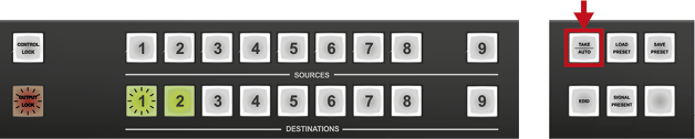
4.4.5. Switching
Changing Connections in TAKE Mode
Step 1.Press and release the desired source button. The pressed source button and all destination buttons which are currently connected to this source will light up. This is an informative display about the current status of the selected input (view only). #crosspoint #switch #takemode

Step 2.Press and release the desired destination button(s) that need to be connected to the selected source. The preselected destination button(s) start(s) blinking.

Step 3.Press and release the Take button to execute switching. Now the selected input is switched to the selected output(s).

ATTENTION!A source button can be pressed twice to preselect all outputs. Outputs that are connected to the pressed input light up and all other outputs start to blink. Some outputs can be unselected if needed, and then pressing Take executes the switching.
INFO:Test input and Preview output ports can be accessed with up and down buttons when the LCD shows their status. An asterisk on the LCD indicates if the port is selected just like the back light for other I/O ports.
INFO:If the pressed destination is locked, then it could not be selected. This is indicated by a short flash of the Output lock when a locked destination is pressed.
Disconnecting or Muting in Take Mode
Step 1.Press and release the selected source button.
The pressed source button and all destination buttons that are currently connected to this source will light up.


Step 2.Press and release the desired destination button shines green. The pressed destination or multiple destination(s) will turn dark.
Step 3.Press and release the Take button to execute disconnection.

INFO:Deselected destinations are disconnected from any source, thus output devices will display a black image, a no signal message, or will turn off automatically.
#mute
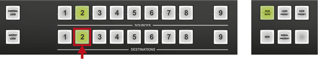
Creating a Connection in Autotake Mode
Step 1.Press and release the desired destination button.
The pressed destination button and the currently connected source button light up green. If no source is connected (the output is muted) no source button will light up.

Step 2.Press and release the desired source button.
Switching is executed immediately. Switching between sources to the selected destination can be done directly.

INFO:The ‘Switch In## Out##’ menu activates automatically when entering Autotake mode to give quick access to the Test input and Preview output ports.
INFO:Test input and Preview output ports can be accessed with up and down buttons when the LCD shows their status. An asterisk on the LCD indicates if the port is selected just like the back light for other I/O ports.
Disconnecting or Muting in AUTOTAKE Mode
To prevent accidental muting, this action is inhibited (disabled) in Autotake mode. Pressing a source button twice would cause accidental disconnecting.
4.4.6. Switching Operations Flowchart
Take Mode #takemode

Autotake Mode

4.4.7. Preset Operations
DEFINITION:A preset stores a configuration regarding all input connections and mute state for all outputs. #preset
INFO:All Lightware matrix routers have 32 user programmable presets. All presets are stored in a non-volatile memory; the router keeps presets even in the case of a power down. Memory numbers are assigned to source buttons 1 to 32. If the frame has fewer buttons, the higher numbered presets are accessible only through software control.
Saving a Preset in Take Mode
Step 1.Create the desired connections that need to be saved.
Step 2.Press and release the Save preset button.

Step 3.Press and release a source button according to the desired memory address (source 1 to 32).

Step 4.Press and release the Take button.
Now the current configuration is stored in the selected memory.

ATTENTION!Preset save action always stores the current configuration for all outputs including mute state, but ignores lock state.
Loading a Preset in Take Mode
Step 1.Press and release the Load Preset button.

Step 2.Press and release a source button according to the desired memory address (source 1 to 32).

Step 3.Press and release the Take button.
Now the selected preset is loaded.

ATTENTION!Loading a preset modifies all output states that are not currently locked.
Saving a Preset in Autotake Mode
Step 1.Create the desired connections that need to be saved.
Step 2.Press and release the Save Preset button.

Step 3.Press and release a source button according to the desired memory address (source 1 to 32).
Now the current configuration is stored in the selected memory.

ATTENTION!Preset save action always stores the current configuration for all outputs including mute state, but lock state is ignored.
Loading a Preset in Autotake Mode
Step 1.Press and release the Load Preset button.

Step 2.Press and release a source button according to the desired memory address (source 1 to 32).
Now the selected preset is loaded.

ATTENTION!Loading a preset modifies all output states that are not currently locked.
DEFINITION:The Output lock means that an input port is locked to an output port and no input change or muting can be executed on that particular output port.

Using Lightware routers it is possible to lock a destination’s state. This feature prevents an accidental switching to the locked destination in the case of an important signal. Destinations can be independently locked or unlocked. Locking a destination does not affect other destinations. #lock #outputlock
View Locked Outputs in Take Mode
Step 1.Press and release the Output Lock button.

Step 2.The Output Lock button starts to blink and all the buttons of any locked destinations light up and remain illuminated for three seconds.
Locking an Output in TAKE Mode
Step 1.Press and release the Output Lock button.
Now the Output Lock button starts to blink and the buttons of all the locked outputs shine green (view state). If no button is pressed for three seconds, the router returns to idle state.

Step 2.Press the desired output buttons.
If an unlit output button is pressed, it starts to blink, indicating that it is preselected for output locking.
Step 3.Press and release the Take button.
The selected destinations are now locked.
Unlocking an Output in Take Mode
Step 1.Press and release the Output Lock button.
Now the Output Lock button starts to blink and all the locked output’s buttons shine green (view state). If no button is pressed for three seconds, the router returns to idle state.

Step 2.If a shining output button is pressed, it goes off to indicate that it is preselected for unlocking.

Step 3.Press and release the Take button.
The deselected destinations are now unlocked.

View Locked Outputs in Autotake Mode
In Autotake mode a destination is selected all the time. Therefore the currently selected output and input buttons are illuminated. The Output Lock button shines regarding the lock state of the current output.
Viewing all locked outputs is not possible in Autotake mode, as pressing the Output Lock button instantly locks or unlocks the current output. #unlock
Locking an Output in Autotake Mode
Step 1.Press and release the required destination button.
Now the selected destination button and the currently configured source button light up (view mode).
Step 2.Press and release the Output Lock button.
Now the Output Lock button lights up in red, and lock function is activated at once. No source can be changed at the locked destination.

Unlocking an Output in Autotake Mode
Step 1.Press and release the required destination button that was previously locked.
Now the selected destination button and the currently configured source button, the Output Lock button light up.

Step 2.Press and release the Output Lock button (deselection).
Now the Output Lock button turns off and the port has been unlocked. #unlock

4.5. The EDID Memory of a Matrix
The EDID memory is non-volatile and consists of four blocks, each for a different purpose. These blocks are:
▪Factory preset EDIDs
▪User saved EDIDs
▪Dynamic EDIDs (EDID of last connected sink on a specific output port)
▪Emulated EDIDs (EDID currently emulated on a specific input port)
EDIDs are numbered from 1 in each block, and they can be referred to as the first letter of the block name and the number of the desired EDID. For example, F02 refers to the second factory preset EDID and D15 refers to the display device’s EDID on output 15.
Dynamic and emulated EDID blocks’ size adapts to the frame size. The memory structure is as follows:
▪F01..F99 Factory Preset EDIDs (not editable)
▪U01..U50 User programmable memories
▪D01..Dxx Last attached monitor’s EDIDs (outputs)
▪E01..Exx Emulated EDIDs (inputs)
All EDIDs (including factory preset; user programmable memories; EDID at other inputs; and EDID at outputs) can be switched and emulated at any of the inputs.
ATTENTION!The attached monitor’s EDID is stored automatically until a new monitor is attached to that particular output. When powering the unit off, the last attached monitor’s EDID remains in non-volatile memory even is the monitor is unconnected.
INFO:MX-CPU2 can handle both 128 Byte EDID and 256 Byte extended EDID structures.
4.5.1. EDID Types
Most of the factory preset EDIDs include only one resolution. This is to force the connected source to give a signal with the needed resolution. However, there are Universal EDIDs as well, which allow many resolutions. The factory EDIDs are divided into groups regarding their type. Some EDIDs are supporting DVI only, some support HDMI, and some are for analog VGA signals. Also, there are some EDIDs for Dual Link DVI resolutions. See the list of factory EDIDs in the Factory EDID List section.
DVI EDIDs do not support audio. The Universal DVI EDID indicates support for many PC (VESA) resolutions.
HDMI EDIDs support embedded audio. These EDIDs have PCM stereo audio format enabled. To allow other audio formats like Dolby and DTS, special EDIDs have to be used. There are three Universal HDMI EDIDs that include the same resolutions, but support different capabilities.
|
EDID |
PCM audio |
other audio |
deep color |
|
Universal_HDMI_PCM |
yes |
no |
no |
|
Universal_HDMI_ALL |
yes |
yes |
no |
|
Universal_HDMI_DC |
yes |
yes |
yes |
Analog EDIDs can be used for input ports that have a VGA (RGBHV) source.
Dual Link DVI EDIDs do not support audio. Use only for Dual Link ports.
Certain I/O boards have extended audio options thanks to the additional auxiliary audio ports. These ports can be configured as input or output ports. This section presents the capabilities of this audio add-on feature. #audio
Supported Boards
▪MX-TPS-IB-S, -A
▪MX-HDMI-3D-IB-S, -A
▪MX-TPS2-IB-SP, -AP
▪MX-4TPS2-4HDMI-IB-A, -S
▪MX-TPS-OB-S, -A
▪MX-HDMI-3D-OB-S, -A
▪MX-TPS2-OB-SP, -AP
4.6.1. Legend of the Figures
Audio de-embedder: Audio de-embedder is able to separate the HDMI video and audio.
Audio embedder: Audio embedder is able to add an audio stream to an HDMI video that does not contain audio.
Interface and I/O switcher: The ‘Interface and I/O module’ configures the audio port as an input or an output and converts the analog input signals to digital and the digital output signals to analog.
(A) No Audio
The embedded audio of the HDMI video is eliminated and the video goes towards the HDMI crosspoint (in the case of input cards) or the output port (in the case of output card) without the audio channel.
.png)
Input Side
_2.png)
Output Side
(B) HDMI Audio Pass-through
The HDMI video (with embedded audio) goes towards the HDMI crosspoint (in the case of input cards) or the output port (in the case of output cards) without any modification.
.png)
Input Side
_2.png)
Output Side
(C) Embed From Aux Audio
It means the original embedded audio is swapped with the auxiliary audio stream and the video – with the embedded auxiliary audio – moves on. #analogaudio
.png)
Input Side
_2.png)
Output Side
(D) De-embed to Aux Audio
The embedded audio of the HDMI video is eliminated and the video goes towards the HDMI crosspoint (in the case of input cards) or the output port (in the case of output card) without the audio channel. The original HDMI audio channel appears on the auxiliary port.
.png)
Input Side
_2.png)
Output Side
#analogaudio
(E) HDMI Pass-through and De-embed to Aux Audio
The HDMI video (with embedded audio) goes towards the HDMI crosspoint (in the case of input cards) or the output port (in the case of output card) without any modification and the audio channel of the HDMI signal appears on the auxiliary port.
.png)
Input Side
_2.png)
Output Side
#analogaudio
The MX-TPS and MX-TPS2 boards have adjustable TPS link mode options for every port separately. The modes can be the following:
▪Auto: The TPS mode is determined automatically.
▪HDBaseT: Ideal for high resolution signals of up to 4K for reduced distances.
▪Long Reach: Ideal for big distances, up to 1080p@60Hz.
▪RS232: Only RS-232 communication is transmitted (at 9600 baud).
▪RS232+Eth: Only RS-232 (at 9600 baud) and Ethernet communication is transmitted.
WARNING!Use only the Auto TPS link mode with third-party devices.
The negotiated TPS working mode is determined by the setting of each party:
|
Selected mode on RX side |
||||||
|
RS232 |
RS232+Ethernet |
HDBaseT |
Long Reach |
Auto |
||
|
Selected mode on RX side |
RS232 |
RS232 |
RS232 |
RS232 |
RS232 |
RS232 |
|
RS232+Ethernet |
RS232 |
RS232+Ethernet |
RS232+Ethernet |
RS232+Ethernet |
RS232+Ethernet |
|
|
HDBaseT |
RS232 |
RS232+Ethernet |
HDBaseT |
Long Reach |
HDBaseT |
|
|
Long Reach |
RS232 |
RS232+Ethernet |
Long Reach |
Long Reach |
Long Reach |
|
|
Auto |
RS232 |
RS232+Ethernet |
HDBaseT |
Long Reach |
HDBaseT* |
|
The available cable lengths can be found in the Maximum Cable Lengths (TP Boards) section.
* If there is a valid HDMI/DVI signal on the TX side, the TPS mode will be HDBaseT on both sides. If the transmitter does not transmit HDMI/DVI signal, the TPS mode will automatically be changed to RS232 only or RS232 + ETH mode. Long reach mode is not available when both sides are set to Auto mode. #rs232 #rs-232 #serial
When one of the devices is configured to manual operation mode selection, the other device may be placed in automatic mode. In this case, the mode transition negotiation is initiated by the host-managed device and the auto-mode device follows through.
4.8. About the Ethernet (TPS and TPS2 Boards)
If the MX-TPS or MX-TPS2 boards are connected to the LAN, they are able to feed Ethernet devices with a standard 10/100 Base-T link. The boards have an Ethernet switch with 1+8 ports. There is no connection between this switch and the other cards, not even the CPU card.
INFO:TPS/TPS2 boards accept independent LAN up-link, which is used to supply devices with a network connection.
The Ethernet labeled connector on the I/O card is connected to the switch directly. The other TPS input and output ports are connected to the switch via the HDBaseT® Tx/Rx IC. (This microchip is able to separate the incoming TPS stream into VIDEO, AUDIO, RS-232, POWER and ETHERNET signal. These signals are packed in the TPS signal as well.)

Ethernet and TPS Connectors for LAN
If the TPS board is connected to the LAN and the Ethernet channel is enabled on a TPS port, the device that is connected* to this port is supplied with a network connection. This connected device can be a TPS extender, or if the TPS port has the AUTO mode setting, it also can be a standard Ethernet equipment. The TPS port with AUTO mode setting is able to recognize the type of the connection, and if it is a standard LAN, the port switches into Ethernet fallback mode. In this case, it is equivalent with a port of an Ethernet switch.
* If the remote power is disabled on a TPS port of a TPS card, it works as a HDBaseT compliant product and the connected device can be a third-party HDBaseT compliant receiver (to the output board) or transmitter (to the input board).
WARNING!Always set the AUTO mode on a board before connecting a third-party device!
4.8.1. Enable and Disable the Ethernet
The LAN can be enabled or disabled for every single TPS port with protocol command. The example command refers to the 2nd port of an MX-TPS output board.
The current state can be queried with the following command:
˃{:TPS#2@SO=?}
The second parameter of the response represents the Ethernet state. If it is 1, then the Ethernet is enabled for the 2nd port of the output board. If it is 0, then the Ethernet is disabled for that port.
˂(TPS#2@SO=A;1;0;0;1;00000000;00000000;0;0000;29;)
The same command is suitable for enabling or disabling this parameter. To enable, use:
˃{:TPS#2@SO=x;1}
˂(TPS#2@SO=A;1;0;0;1;00000000;00000000;0;0000;34;)
To disable, swap the 1 to 0:
˃{:TPS#2@SO=x;0}
˂(TPS#2@SO=A;0;0;0;1;00000000;00000000;0;0000;34;)
ATTENTION!Connecting the MX-CPU card to the LAN via MX-TPS board is not recommended.
INFO:The first parameter is the working mode. The x character is recommended be used when setting the command, because the x does not change the parameter, so it remains unaltered.
For more information about the TPS command, see the TPS and TPS2 Port section.
4.8.2. Avoid Causing an Ethernet Loop
A TPS board (actually the Ethernet switch of the board) can be uplinked to the same LAN only once to avoid an Ethernet loop. In this case, if the other network devices are not able to handle Ethernet loops, the LAN network may break down.
Example
The TPS board connects first to the router of the ROOM 1 via the switch of the ROOM 2. The HDMI-TPS-TX95 in the ROOM 3 is connected to the LAN via TPS link. If the installer does not know the transmitter has already connected to the LAN via TPS and links the transmitter to the switch – shown by the brown arrow in the picture – it results in an Ethernet loop – demonstrated by the red lines on the picture below.

Ethernet Loop
4.9. LCD Control Panel Operation
4.9.1. Basic Concept
There are three operating modes of the LCD menu.
Normal Mode
Most settings can be done in this mode. It is active when none of the EDID or the SIGNAL PRESENT button shine.
EDID Mode
Use this mode to set up the emulated EDID on the inputs, learn EDID form the outputs or to view the EDID memory. Enter or exit this mode by pressing the EDID button. The illuminated EDID button shows that this mode is active.
Signal Present Mode
This mode is for checking the presence of incoming signals and display devices. Enter or exit this mode by pressing the SIGNAL PRESENT button. The illuminated SIGNAL PRESENT button shows that this mode is active.
Navigation
The front panel LCD has 4 lines and 20 characters in each line. The navigation buttons and the applied symbols are listed as follows:
|
Button |
Function |
|
|
|
up |
scroll between menu items |
|
|
down |
|
|
« |
left |
step into/out from a submenu or change the value of the current parameter |
|
» |
right |
|
|
|
enter |
step in a submenu or execute changes |
|
|
escape |
step back to the previous submenu |
|
Symbol |
Function |
|
|
~ |
indicates the currently selected menu item |
|
|
>> |
shows the current submenu |
|
|
< and > |
changeable values are in angle brackets |
|
|
[*] |
indicates an active function |
|


Menu Structure


The Up ▲ and down ▼ buttons select between menu items. More items become visible when scrolling down. The Enter or right ► buttons step in submenus.
4.9.2.1. IP Settings Menu


This menu contains the IP status submenu, DHCP enable checkbox and TCP/IP port value. If the DHCP is switched off, then IP address, Default gateway and Subnet mask can be set as well. Changes take place only when Save settings is executed. Press the escape button to return to the main menu without saving any changes.

IP Status Submenu
Navigate to this submenu and press the enter or right ► buttons to see the current IP address, port, gateway and subnet mask. No changes can be made in this submenu. Press escape to return to the previous menu.
DHCP Enable Checkbox #dhcp

Navigate to this item with the up ▲ and down ▼ buttons. Pressing enter toggles the DHCP state. If DHCP is inactive then the IP address, Gateway, and Subnet mask can be set manually to fix values.
Port Value

Navigate to this item with the up ▲ and down ▼ buttons. Use the left ◄ and right ► buttons to change the TCP/IP port value.
#ipaddress #network
IP Address Submenu

Navigate to this item with the up ▲ and down ▼ buttons. This submenu appears only if DHCP is disabled. Press the enter or right ► button to step in.

The four parts of the fix IP address can be set separately. Use the left ◄ and right ► buttons to select the part, and then use the up ▲ and down ▼ buttons to change the value of that part. Press the escape button to return to the previous menu.
Default Gateway Submenu
This submenu can be used the same as the IP address submenu.
Subnet Mask Submenu
This submenu can be used the same as the IP address submenu.
Save Settings

Any changes made in the IP settings menu come alive only when Save settings is executed. To do this, navigate to this item with the up ▲ and down ▼ buttons, then press the enter or right ► buttons.
The Operation in progress message appears on the LCD. If saving the settings succeeds, the Operation done! message is shown for 2 seconds.
INFO:If you get the Operation Failed message, please try again.
4.9.2.2. RS-232 Settings Menu


The serial port baud rate value can be set here. Use the left ◄ and right ► buttons to change the baud rate value. Changes take place immediately when modifying the value. Press the escape button to return to the main menu.
#rs232 #rs-232 #serial
4.9.2.3. Protocol Settings Menu

Navigate to this menu in the main menu list and press the enter or the right ► button to set the communication protocol for each interface separately.

Use the up ▲ and down ▼ buttons to select an interface, and then select the desired protocol with the left ◄ and right ► buttons. Changes take place immediately when modifying the value. A beep sound indicates that the protocol is changed.

Press the escape button to return to main menu.
4.9.2.4. Input Settings Menu

Navigate to this menu in the main menu list and press the enter or right ► button.
Select Input Port Submenu

Use the up ▲ and down ▼ buttons to select the port that needs adjustment and then press the enter or right ► button.
The items in the following submenu depend on the interface board type, as different I/O boards have different capabilities.
Input Port Settings Submenu (DVI-D Type)

Supported Boards: MX-DVID-IB, MX-DVI-TP-IB(+)
The input cable equalization can be set in 0.1dB increments from 0 dB to 41.0 dB, or Auto. Use the left ◄ and right ► buttons to change the value.
Input Port Settings Submenu (HDMI Type)

Supported Boards: MX-HDMI-IB, MX-DVI-HDCP-IB, MX-HDMI-TP-IB, MX-CPU2 Test input
Use the up ▲ and down ▼ buttons to select the setting to be changed.
The input cable equalization can be set to 3, 9, 25, 35, 40 dB, or Auto.

Use the left ◄ and right ► buttons to change the value. (exception: the MX-CPU2 Test input port does not have cable equalization.)

The HDCP capability on the input port can be enabled or disabled with the HDCP enable checkbox. Press enter to toggle its state.
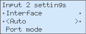
The Color range conversion can be set to compress, expand or Auto. Use the left ◄ and right ► buttons to change the value.
Input Port Settings Submenu (DVI-I Type)
Supported Boards: MX-DVII-HDCP-IB, MXD-UMX-IB
Use the up ▲ and down ▼ buttons to select the parameter to be changed. Use the left ◄ and right ► buttons to change the value.
The Interface parameter sets the signal type that is connected to the input port. It can be set to Auto, Analog auto, Analog RGB, Analog YUV, or Digital.

The Port mode setting affects the signal type that is sent to the crosspoint. All incoming analog signals are digitized on the input. DVI or HDMI signal can be sent to the crosspoint. This parameter can be fixed DVI or pass HDMI. The latter option uses HDMI signal if the incoming signal is HDMI as well. #hdcp

The Audio source parameter is accessible only with the MXD-UMX-IB. It can be set to No Audio, DVII (embedded audio) or Add-on. The latter option takes the audio signal from the analog stereo or the S/PDIF inputs according to the Add-on source setting.

The HDCP capability on the input can be enabled or disabled with the HDCP enable setting. The Analog settings submenu affects the analog video input parameters.


The Add-on source setting is accessible only with the MXD-UMX-IB. The analog stereo and S/PDIF conversion functions can be set here. Two signal conversions are shown. S represents the S/PDIF port, An represents the analog stereo port and D represents the digital audio, which is embedded in the HDMI signal on the video port. Possible options are shown below: #analogaudio #audio


The Analog audio Input submenu contains settings like volume, balance, etc. for the analog stereo audio port when it is configured as an input.
Available only at the MXD-UMX-IB.
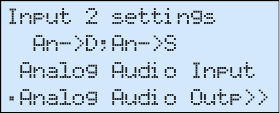
The Analog audio Output submenu contains settings like volume, balance, etc. for the analog stereo audio port when it is configured as an output.
Available only at the MXD-UMX-IB.

Input Port Settings Submenu (DVIDL type)
Supported Boards: MX-DVIDL-IB
The input cable equalization can be set to 3, 9, 25, 35, 40 dB, or Auto. Use the left ◄ and right ► buttons to change the value.

Input Port Settings Submenu (3G-SDI type)
Supported Boards: MX-3GSDI-IB
Use the up ▲ and down ▼ buttons to select the parameter to be changed. Use the left ◄ and right ► buttons to change the value.

The Equalization can be set to Auto (recommended) or 0 dB. The later setting disables equalization.
The Audio source selects the audio signal that is embedded in the forwarded HDMI stream: it can be set to SDI, S/PDIF or No audio.

The Video mode sets the signal type to DVI or HDMI mode, which is sent towards the matrix crosspoint. The Audio dependent mode sends HDMI signal to the crosspoint if the audio source is set to embed audio from SDI or S/PDIF. The Frame compatible mode sets the signal type according to the output board types in the matrix frame. If there are only HDMI compatible output boards, then the signal type will be HDMI.

The incoming SDI embedded audio channels can be rearranged and allocated to HDMI audio channels. The channel allocation preset can be selected with the Aud.Preset setting. SDI audio allocation presets are common for all SDI input ports in the matrix.
Input Port Settings Submenu (TPS type)
Supported Boards: MX-TPS-IB, -S, -A, MX-TPS2-IB-P, -AP, -SP,
MX-4TPS2-4HDMI-IB-P*, -AP*, -SP*
* only the four TPS2 ports of the boards.

Use the up ▲ and down ▼ buttons to select the parameter to be changed. Use the left ◄ and right ► buttons to change the value.
The HDCP capability on the input port can be enabled or disabled with the HDCP enable checkbox. #hdcp

Press enter to toggle its state.

The Test pattern generator helps test and troubleshoot video hook-ups and displays. Use the left ◄ and right ► buttons to change the value. On turns on, Off turns off the test pattern generator. If it is off, the output gives a solid black, 480p video signal. (This is the default value.) In the case of No signal mode, the output does not give any signal.

Three options can be selected for the resolutions of the TPG: 480p 60Hz, 576p 60Hz and Odd p. signal. Odd p. signal means the resolution of the test pattern is the same as the closest smaller or equal odd input’s resolution. (Input 1 for the input 1 and 2, Input 3 for input 3 and 4, and so on…) If there is no video signal on the odd input, the generator gives a 480p signal. #nosyncscreen #testpattern
The pattern can be solid green, blue, black, white or black and white ramp and chessboard or color bar. The cycle changes all the listed ones periodically.

The Audio mode settings are available in the case of the MX-TPS-IB-A and MX-TPS-IB-S boards. It can be selected here which is embedded in the forwarded HDMI signal: it can be set to No audio (A), HDMI audio passth. (B), Embed from Ext (C), Deembed to Ext (D) or HDMI + deemb (E).

For detailed information about the audio settings, see the Audio Options section. #analogaudio #audio
The Analog Audio Input settings are available in the case of the MX-TPS-IB-A board. The submenu contains the attributes of the analog audio signal.

If the auxiliary audio port is defined as input (embed), the options are: volume, balance, gain, phase (invert), DC Filter.
In the case of output (deembed), the options are: volume, balance, bass, treble, deemphasis, phase (invert), DC Filter.
The TPS mode can be HDBaseT, Longreach, Automatic, RS232 only and RS232+ETH only.
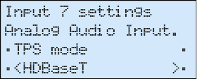

For detailed information about the TPS modes, see the TPS Link Modes section.
The PoE setting (remote Power over Ethernet) is available only in the case of TPS2 boards. Set the desired mode (enable/disable) on the given port. #gain #nosyncscreen #testpattern
Input Port Settings Submenu (HDMI-3D type)
Supported Boards: MX-HDMI-3D-IB, -S, -A; MX-DVI-4K-IB
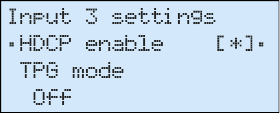
Use the up ▲ and down ▼ buttons to select the parameter to be changed. Use the left ◄ and right ► buttons to change the value.
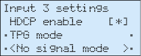
The HDCP capability on the input port can be enabled or disabled with the HDCP enable checkbox.
Press enter to toggle its state.

The Test pattern generator makes it simple to test and troubleshoot video hook-ups and displays. Use the left ◄ and right ► buttons to change the value. On turns on, Off turns off the test pattern generator. If it is off, the output gives a solid black, 480p video signal. (This is the default value.) In the case of No signal mode, the output does not give any signal. #hdcp

Three options can be selected for the resolutions of the TPG: 480p 60Hz, 576p 60Hz and Odd p. signal. Odd p. signal means the resolution of the test pattern is the same as the closest smaller or equal odd input’s resolution. (Input 1 for the input 1 and 2, Input 3 for input 3 and 4, and so on…) If there is no video signal on the odd input, the generator gives a 480p signal.
The pattern can be solid green, blue, black, white or black and white ramp and chessboard or color bar. The cycle changes all the listed ones periodically.

The Audio mode settings are available in the case of the MX-HDMI-3D-IB-A and MX-HDMI-3D-IB-S boards. It can be selected here which is embedded into the forwarded HDMI signal: it can be set to No audio (A), HDMI audio passth. (B), Embed from Ext (C), Deembed to Ext (D) or HDMI + deemb (E).
The Analog Audio Input settings are available in the case of an MX-TPS-IB-A board. The submenu contains the attributes of the analog audio signal. #audio #analogaudio
If the auxiliary audio port is defined as input (embed), the options are: volume, balance, gain, phase (inversion), DC Filter.
In the case of output (deembed), the options are: volume, balance, bass, treble, deemphasis, phase (inversion), DC Filter.
Input Port Settings Submenu (HDMI-OPT type)
Supported Boards: MX-HDMI-OPT-IB-SC, MX-HDMI-OPT-IB-LC,
MX-HDMI-OPT-IB-ST, MX-HDMI-OPT-IB-NT
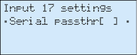
The remote serial communication feature can be enabled or disabled.
For the RS-232 control over fiber function (see details in the RS-232 Command Transmission section), enable the Serial Passthr option. That allows the serial commands to be sent over the fiber cable. It is recommended to disable this feature if not used.
4.9.2.5. Output Settings Menu

Navigate to this menu in the main menu list and press enter or right ► button.
Select Output Port Submenu

Use the up ▲ and down ▼ buttons to select the port that needs adjustment and then press the enter or right ► button.
The items in the following submenu depend on the interface board type, as different I/O boards have different capabilities. Use the up ▲ and down ▼ buttons to select the setting to be changed.
Output Port Settings Submenu (DVI-D type)
Supported Boards: MX-DVID-OB, MX-DVI-TP-OB(+), MX-DVI-OPT-OB-R

The Deskewing can be enabled or disabled with this checkbox. The default setting is disabled. Press enter to toggle its state.

The Deskew level can be set using the left ◄ and right ► buttons. Has an effect only if the deskewing is enabled. The default setting is 4.

The PLL filter can be enabled or disabled with this checkbox. The default setting is enabled. Press enter to toggle its state.
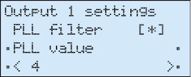
The PLL value can be set using the left ◄ and right ► buttons. Has an effect only if the PLL filter is enabled. The default setting is 4.
Output Port Settings Submenu (HDMI type)
Supported Boards: MX-HDMI-OB, MX-DVI-HDCP-OB, MX-HDMI-TP-OB, MXD-HDMI-TP-OB, MX-CPU2 Preview output
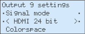
The Signal mode can be set to DVI, HDMI 24bit, HDMI 30bit, HDMI 36bit or Auto mode. The Auto option sets the signal mode regarding the attached display device’s EDID and the incoming signal. Use the left ◄ and right ► buttons to change the value.

The Colorspace can be set to RGB, YUV444, YUV422 or Auto. Convert the color space on the output to the given type. Please note that DVI signals support only RGB color space. Use the left ◄ and right ► buttons to change the value.

The Colorrange can be set to compress, expand or Auto. Use the left ◄ and right ► buttons to change the value.

With the PCM subsample setting, the 2-channel PCM audio can be subsampled by 2x or 4x. The minimum of the new sampling frequency is 44.1 kHz. Use the left ◄ and right ► buttons to change the value.
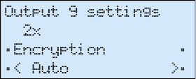
The Encryption option sets the HDCP encryption on the output. The Auto setting applies encryption when the incoming signal is encrypted. The Always setting forces encryption on any incoming video signal. Use the left ◄ and right ► buttons to change the value.
Output Port Settings Submenu (DVIDL type)
Supported Board: MX-DVIDL-OB

The DualLink mode can be set to enable or disable the wires needed for Dual-Link signals. The Disable mode virtually disconnects the Dual-Link TMDS wires. The Auto mode considers the currently connected input port type. Use the left ◄ and right ► buttons to change the value.
Output Port Settings Submenu (OPT type)
Supported Boards: MX-DVI-OPT-OB, MX-HDMI-OPT-OB

The laser on each output port can be enabled or disabled. Disabling unused laser outputs can lengthen their lifespan. Use the left ◄ and right ► buttons to change the value.
Output Port Settings Submenu (TPS type)
Supported Boards: MX-TPS-OB, -S, -A, MX-TPS2-OB-P, -AP, -SP; MX-4TPS2-4HDMI-OB, -A, -S, -P, -AP, -SP
Use the up ▲ and down ▼ buttons to select the parameter to be changed. Use the left ◄ and right ► buttons to change the value.
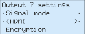
The Signal mode can be set to DVI, HDMI or Auto mode. The Auto option sets the signal mode regarding the attached display device’s EDID and the incoming signal. Use the left ◄ and right ► buttons to change the value.

The Encryption option sets the HDCP encryption on the output. The Auto setting applies encryption when the incoming signal is encrypted. The Always setting forces encryption on any incoming video signal. Use the left ◄ and right ► buttons to change the value. #hdcp
For detailed information about the HDCP modes, see the HDCP Management section. #nosyncscreen #testpattern

The Test pattern generator makes it simple to test and troubleshoot video hook-ups and displays. Use the left ◄ and right ► buttons to change the value. On turns on, Off turns off the test pattern generator. If it is on, the output gives a solid red, 480p video signal. (This is the default value.) In the case of No signal mode, the output does not give any signal.

Three options can be selected for the resolutions of the TPG: 480p 60Hz, 576p 60Hz and Odd p. signal. Odd p. signal means the resolution of the test pattern is the same as the closest smaller or equal odd input’s resolution. (Input 1 for the input 1 and 2, Input 3 for input 3 and 4, and so on…) If there is no video signal on the odd input, the generator gives 480p signal.
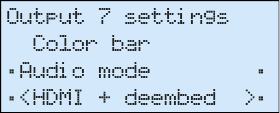
The pattern can be solid green, blue, black, white or black and white ramp and chessboard or color bar. The cycle changes all the listed ones periodically.
The Audio mode settings are available in the case of the MX-TPS-OB-A and MX-TPS-OB-S boards. It can be selected here which is embedded in the forwarded HDMI signal: it can be set to No audio (A), HDMI audio passth. (B), Embed from Ext (C), Deembed to Ext (D) or HDMI + deemb (E).

The DVI or HDMI 5V line can be controlled on an output port with the PWR5V mode. If it is On, the 5VDC is always active. If it is Off, the port never sends the 5 VDC. #power5v
ATTENTION!If the 5V line is off, sink devices do not send HotPlug signal in most cases and their EDIDs will not be read.
The Auto mode means the port gives the 5V, but if the video signal changes (e.g. resolution), it turns off the 5V for 1 sec and turns it on again.
TIPS AND TRICKS:This mode is useful for sink devices that are not able to handle the changing of the video signal properly.

The Analog Audio Output settings are available in the case of boards with analog audio add-on ("-A" extension). The submenu contains the attributes of the analog audio signal.

If the auxiliary audio port is defined as input (embed), the options are the followings: volume, balance gain, phase (inversion), DC Filter.
In the case of output (deembed), the options are: volume, balance, bass, treble, deemphasis, phase (inversion), DC Filter.

The TPS mode can be HDBaseT, Longreach, Automatic, RS232 only and RS232+ETH only.
For detailed information about the TPS modes, see the TPS Link Modes section.

The PoE setting (remote Power over Ethernet) is available only in the case of TPS2 boards. Set the desired mode (enable/disable). #audio #analogaudio #gain
Output Port Settings Submenu (HDMI-3D type)
Supported Boards: MX-HDMI-3D-OB, MX-HDMI-3D-OB-S,
MX-HDMI-3D-OB-A, MX-4TPS2-4HDMI-OB, -A, -S, -P, -AP, -SP,
MX-DVI-4K-OB #hdcp

Use the up ▲ and down ▼ buttons to select the parameter to be changed. Use the left ◄ and right ► buttons to change the value.
The Signal mode can be set to DVI, HDMI or Auto mode. The Auto option sets the signal mode according to the attached display device’s EDID and the incoming signal. Use the left ◄ and right ► buttons to change the value.

The Encryption option sets the HDCP encryption on the output. The Auto setting applies encryption when the incoming signal is encrypted. The Always setting forces encryption on any incoming video signal. Use the left ◄ and right ► buttons to change the value. For detailed information about the HDCP modes see the HDCP Management section.

The Test pattern generator makes it simple to test and troubleshoot video hook-ups and displays. Use the left ◄ and right ► buttons to change the value. On turns on, Off turns off the test pattern generator. If it is off, the output gives a solid black, 480p video signal. (This is the default value.) In the case of No signal mode, the output does not give any signal.
#nosyncscreen #testpattern

Three options can be selected for the resolutions of the TPG: 480p 60Hz, 576p 60Hz and Odd p. signal. Odd p. signal means the resolution of the test pattern is the same as the closest smaller or equal odd input’s resolution. (Input 1 for the input 1 and 2, Input 3 for input 3 and 4, and so on…) If there is no video signal on the odd input, the generator gives a 480p signal.

The pattern can be solid green, blue, black, white or black and white ramp and chessboard or color bar. The cycle changes all the listed ones periodically.

The Audio mode settings are available in the case of the MX-HDMI-3D-OB-A and MX-HDMI-3D-OB-S boards. It can be selected here which is embedded in the forwarded HDMI signal: it can be set to No audio (A), HDMI audio passth. (B), Embed from Ext (C), Deembed to Ext (D) or HDMI + deemb (E). #power5v
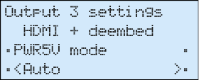
The DVI or HDMI 5V line can be controlled on an output port with the PWR5V mode. If it is On, the 5V DC is always active. If it is Off, the port never sends the 5 V DC.

ATTENTION!If the 5V line is off, sink devices do not send HotPlug signal in most cases and their EDIDs will not be read.
The Auto mode means the port gives the 5V, but if the video signal changes (e.g. resolution), it turns off the 5V for 1 sec and turns it on again.
INFO:This mode is useful for sink devices that are not able to handle the changing of the video signal properly.
The Analog Audio Output settings are available in the case of the MX-TPS-OB-A board. The submenu contains the attributes of the analog audio signal.
If the auxiliary audio port is defined as input (embed), the options are: volume, balance, gain, phase (inversion), DC Filter.

In the case of output (deembed), the options are: volume, balance, bass, treble, deemphasis, phase (inversion), DC Filter.
Output Port Settings Submenu (HDMI-OPT-R type)
Supported Boards: MX-HDMI-OPT-OB-R-SC, MX-HDMI-OPT-OB-R-LC, MX-HDMI-OPT-OB-R-ST, MX-HDMI-OPT-OB-R-NT

Use the up ▲ and down ▼ buttons to select the parameter to be changed. Use the left ◄ and right ► buttons to change the value.
The Signal mode can be set to No change, DVI or HDMI. The No change option does not convert the output signal into DVI or HDMI video. Use the left ◄ and right ► buttons to change the value. #hdcp

The Encryption option sets the HDCP encryption on the output. The Auto setting applies encryption when the incoming signal is encrypted. The Always setting forces encryption on any incoming video signal. Use the left ◄ and right ► buttons to change the value. For detailed information about the HDCP modes, see the HDCP Management section.


The Test pattern generator makes it simple to test and troubleshoot video hook-ups and displays. Use the left ◄ and right ► buttons to change the value. On turns on, Off turns off the test pattern generator. If it is off, the output gives a solid black, 480p video signal. (This is the default value.) In the case of No signal mode the output does not give any signal.
Three options can be selected for the resolutions of the TPG: 480p 60Hz, 576p 60Hz and Odd p. signal. Odd p. signal means the resolution of the test pattern is the same as the closest smaller or equal odd input’s resolution. (Input 1 for the input 1 and 2, Input 3 for input 3 and 4, and so on…) If there is no video signal on the odd input, the generator gives a 480p signal.
The pattern can be solid green, blue, black, white or black and white ramp and chessboard or color bar. The cycle changes all the listed ones periodically.

The laser on each output port can be enabled or disabled. Disabling unused laser outputs can lengthen their lifespan. Use the left ◄ and right ► buttons to change the value. The remote serial communication feature can be enabled or disabled. #nosyncscreen #testpattern

For the RS-232 control over fiber function (see details in the RS-232 Command Transmission section), enable the Serial Passthrough option. It allows the serial commands to be sent over the fiber cable. It is recommended to disable this feature if not used.
Output Port Settings Submenu (AUDIO type)
Supported board: MX-AUDIO-OB-A
Use the up ▲ and down ▼ buttons to select the parameter to be changed. Use the left ◄ and right ► buttons to change the value.
The submenu contains the attributes of the analog audio output signal. The available options are: volume, balance, bass, treble, deemphasis, phase (inversion).
4.9.2.6. Hardware Status Menu


Navigate to this menu in the main menu list and press the enter or right ► button. The monitored voltage levels, fan speeds, etc. can be scrolled through with the up ▲ and down ▼ buttons. Press the escape button to return to the main menu.
4.9.2.7. Router Status Menu


Navigate to this menu in the main menu list and press the enter or right ► button. This view is shown by default after powering on the LDC. Matrix serial number, current IP address, TCP/IP port, and the RS-232 baud rate is shown. Press the escape button to return to the main menu.
4.9.2.8. Card Information Menu

Navigate to this menu in the main menu list and press the enter or right ► button.

The installed I/O board types can be checked. Navigate to a slot with the up ▲ and down ▼ buttons, and then press the enter or right ► button to see the board information for the selected slot. Press the escape button to return to the main menu.

The product name and version is shown of the installed board in the selected slot. Press the escape button to return to the previous menu.
4.9.2.9. Firmware Versions Menu
Navigate to this menu in the main menu list and press the enter or right ► button. #firmwareversion


The current firmware version can be checked for each controller module. Use the up ▲ and down ▼ buttons to scroll through modules. Press the escape button to return to the main menu.
4.9.2.10. Factory Reset Menu
This menu contains submenus that can reload factory defaults for certain group of settings separately.


After selecting an option (submenu) with the up ▲ and down ▼ buttons, press the enter or right ► button to execute it. Any reset operation has to be confirmed. Some operations need to reboot the matrix. Press the escape button to return to the main menu without any changes.
IP Reset Submenu

This operation reloads the factory default IP settings.

|
Parameter |
Default value |
|
IP address |
192.168.254.254 |
|
Port number |
10001 |
|
Subnet mask |
255.255.0.0 |
|
Gateway |
0.0.0.0 |
Select YES and press the enter or right ► button to execute the operation. Select NO or press escape to return to the previous menu without any changes.
IO Card Reset Submenu

This operation reloads the factory default settings for all input and output ports on all currently installed I/O boards. The matrix will reboot after execution.

Select YES to execute the operation. Select NO or press escape to return to the previous menu without any changes.
EDID Reset Submenu

This operation emulates the factory default F49 EDID (Universal HDMI with deep color) to all input ports on all currently installed I/O boards.

Select YES to execute the operation. Select NO or press escape to return to the previous menu without any changes.
HDCP Key Reset Submenu

This operation clears the HDCP key cache in the matrix. This is useful when a source cannot accept as many keys as the matrix stores.

Select YES to execute the operation. Select NO or press escape to return to the previous menu without any changes.
Protocol Reset Submenu

This operation sets the Lightware communication protocol for every control interface (LAN, RS-232, USB). Beep sounds indicate protocol change.

Select YES to execute the operation. Select NO or press escape to return to the previous menu without any changes.
All Reset Submenu

This operation resets all settings mentioned above. The matrix will reboot.

Select YES to execute the operation. Select NO or press escape to return to the previous menu without any changes.
4.9.2.11. HDCP Keycounter Menu


This menu allows to test source devices to see how many HDCP keys they can accept. Select the input port that the tested device is connected to with the up ▲ and down ▼ buttons, and then press the enter or right ► button to execute the key-counter test. Press the escape button to return to the main menu.
The availability of this test depends on the input port type. The menu lists only the ports capable of running this test (HDMI or DVI-HDCP inputs).

A message appears showing the test progress. It can take several minutes to complete. After the test is finished, the result is shown. Press enter to acknowledge the result and return to the previous menu.

4.9.2.12. View Log Menu
Navigate to this menu in the main menu list and press the enter or right ► button.


System events and errors can be checked in this menu. Use the up ▲ and down ▼ buttons to scroll between the log entries. The first line of each log entry shows the current entry number, the number of all entries, and the level of the current entry. The second line is the name of the event that created the entry. The third line shows a hexadecimal parameter and an occurrence counter. The occurrence shows how many times the event happened since the last startup.
|
Level |
Description |
|
Notice |
Not an error. Initialization information. |
|
Warning |
Possible problem without influencing normal operation. |
|
Matter |
Problem that may lead to further errors. |
|
Error |
Serious error. Must report to Lightware support. |
|
Fatal |
Fatal error. Normal operation is not possible. |
See more details in the Error Handling section. Press escape to return to the main menu.
INFO:This log can contain NOTICEs and WARNINGs under normal operation. These entries do not mean that there is any problem with the matrix!
4.9.2.13. Switch In## Out## Menu

The numbers shown in the name of this menu depend on the router frame.

Switch In17 Out17 appears for MX-FR17, and Switch In33 Out33 appears for MX-FR33, MX-FR33L, and MX-FR33R. For MX-FR9, MX-FR80R and MX-FR65R this menu is disabled.
Navigate to this menu in the main menu list and press the enter or right ► button. This menu allows to switch the Test input and Preview output ports from the front panel. These ports do not have a dedicated button with backlight like other I/O ports.
Use the up ▲ button to the select the Test input port and the down ▼ button to select the Preview output port. The checkboxes act like the backlight for the illuminated I/O port buttons. If the asterisk appears next to the port name, it means it is selected.
This menu is activated for three seconds every time when an I/O button is pressed on the front panel. This menu also appears automatically when the AUTOTAKE mode is activated. This gives quick access to the Test input and Preview output ports without navigating to this menu. However, if this menu is selected manually from the main menu list, it remains active until the escape • button is pressed.
Input #80 Menu

This menu only appears in the FR80R and FR65R frames.

Navigate to this menu in the main menu list and press the enter or right ► button.
The 80th port of the crosspoint can be selected to use the Test input port from the CPU board or the 8th port from the 10th input board.
INFO:The 80th input port of the crosspoint is multiplexed between the Test input port and the 8th port of the 10th input board. This switch is independent from the crosspoint state. The selected port (Test input or Input board #10) will be available as the 80th input on the crosspoint switch.
Config Backup Menu


Navigate to this menu in the main menu list and press the enter or right ► button.
The full matrix configuration, including every port setting and EDIDs, can be saved and reloaded later.

To save the current configuration, select Save config now! and press the enter or right ► button. A confirmation message appears, then the progress starts. A status indicator shows the progress. This may take up to 1 minute. After the saving finished, a message appears: ‘Ready! 20160803-1411.cfg’
The configuration file name includes the date and time when the configuration was saved in YYYYMMDD-HHMM format. For example, the file 20160803-1411.cfg was saved at 14:11 on 3rd August, 2016.

To reload a previously saved configuration, go to the Config to load item with the up ▲ and down ▼ buttons and then select the desired configuration file with the left ◄ and right ► buttons. Press enter to reload the selected configuration. Please note this will change every setting in the matrix (I/O port parameters, crosspoint presets, EDIDs, etc.) and the previous state could be restored only if the configuration was saved earlier.

A confirmation message appears, then the progress can be started. This may take several minutes. A status indicator shows the progress. After the configuration reloading finished, a message appears: ‘Ready!’ and the matrix reboots.

ATTENTION!The matrix must not be switched off during a configuration reload process! If the power goes off, then the matrix will restart with factory default settings.
4.9.3. LCD Menu Pop-up Messages
ALERT Screen

This pop-up screen appears when a high-level error occurs in the matrix. Press the enter button to dismiss this alert and jump to the system log entry. Use the up ▲ and down ▼ buttons to scroll between the log entries. Please contact support@lightware.com.
4.9.4. EDID Mode
To enter or to exit this mode, press and release the EDID button. EDID mode is active when the EDID button is illuminated on the front panel. All EDIDs are referred to by their memory location e.g. F49 or D03, see the EDID Menu section. #edid

Select menu items with the up ▲ and down ▼ buttons and then press the enter or right ► button to step in submenus. Press the escape • button to return to the main EDID management menu.
INFO:Not executed operation is canceled when you exit from the EDID menu.
INFO:Source and destination buttons are disabled while EDID mode is active.
View EDID Menu

All the stored EDIDs can be checked through this menu. The EDID types are grouped in submenus.

The most important information about each EDID is shown in the submenu.
Use the left ◄ and right ► buttons to select the desired EDID. The monitor name and the preferred resolution can be checked.
Save EDID Menu

The EDID from any connected monitor can be saved to user memory slots. Select the dynamic EDID of the output port with the left ◄ and right ► buttons. Then press down ▼ and select the user EDID slot where the monitor’s EDID would be stored.

After the desired dynamic EDID and user memory is selected, go to Save! and press the enter or right ► button to store the EDID.
Switch EDID Menu

The emulated EDIDs can be changed in this menu. Dynamic, User or Factory EDIDs can be selected in the top row with the left ◄ and right ► buttons. The preferred resolution of the selected EDID is shown in the second row of the screen.
Press down ▼ and then select the input port with the left ◄ and right ► buttons.
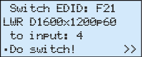
After the desired EDID and input port is selected, go to Do switch! and press the enter or right ► button to change the emulated EDID.
The Operation in progress message appears on the LCD. If switching the EDID succeeds, then the Operation done! message is shown for 2 seconds.
4.9.5. Signal Present Mode

Press the Signal present button to enter or exit this mode. The Signal present mode is active when the button is illuminated.
In this mode the source and destination buttons show the actual connection state of the corresponding port, and the actual crosspoint state can be checked on the LCD menu.
Press the up ▲ or down ▼ buttons to navigate between the submenus and screens.
ATTENTION!Source and destination buttons are disabled while Signal Present mode is active.
Source and Destination Buttons
If a source button is illuminated, then a signal is present on that source. If a destination button is illuminated, then a powered display is attached to this output (Hot Plug Detect signal is present).
INFO:Keep in mind that I/O boards have different capabilities to sense signals and monitors, therefore this function could be inadequate with certain I/O boards.
TIPS AND TRICKS:You can quickly check the cable connections with this feature.
Signal on Test Input

This screen shows the actual incoming signal resolution on the Test input port.
Press the up ▲ or down ▼ button to go to the previous or next screen.
Signal on Preview Output

This screen shows the actual signal resolution that presents on the Preview output port.
Press the up ▲ or down ▼ button to go to the the previous or next screen.
Crosspoint Status

Navigate to the Crosspoint submenu item with the up ▲ and down ▼ buttons and then press the enter or right ► button to step in this submenu.
The crosspoint connections are shown. One screen shows connected inputs for nine outputs. Further outputs can be checked by scrolling through screens with the up ▲ and down ▼ buttons.
Every output’s connection is shown like this: ‘o01i03’. In this example, it means that input 3 is connected to output 1.
Press the escape button to return to the main Signal present menu.
Lightware matrix routers can be controlled through various interfaces remotely. The feature allows functions that are not accessible via the front panel and useful for system integrators and operators to control multiple devices in a complicated system through a single user interface.
The user can connect to the matrix through
▪Ethernet (TCP/IP),
▪Serial port (RS-232 or RS-422),
▪USB (if available on the matrix frame front panel)
After establishing the connection, there is no difference between the connection types (except the RICOD and some rare cases, which are uniquely noted).
The RICOD enables only switching inputs, locking and unlocking device’s buttons.
The available remote connections and the relating chapters are listed below.
|
User Interface |
Connection Type |
Further Information |
||
|
Ethernet Port |
RS-232 Serial Port |
USB Port |
||
|
Built-in website |
ü |
- |
- |
|
|
Lightware Device Controller software |
ü |
ü |
ü |
|
|
Third party control system |
ü |
ü |
- |
|
ATTENTION!Ethernet port can be connected to a LAN hub, switch or router with a UTP patch cable. If connecting to a computer directly, a cross-link UTP cable has to be used!
User Interface Comparison
The built-in website and Lightware Device Controller have similar capabilities. Differences and features are described the table below.
* The feature is not supported in Apple Safari browser.
|
Function |
Lightware Device Controller Software |
Built-in Website |
|
Platform |
Windows, macOS |
Mozilla Firefox, Apple Safari, Google Chrome |
|
Installation |
installation required |
web browser needed only |
|
I/O crosspoint switch |
ü |
ü |
|
I/O and preset names |
ü |
ü |
|
I/O port properties |
ü |
ü |
|
Preview presets |
ü |
ü |
|
Easy EDID creator |
ü |
ü |
|
EDID editor |
ü |
ü |
|
EDID load / save |
ü |
ü * |
|
View error log |
ü |
ü |
|
FW update of TPS boards |
ü |
ü |
4.10.2. Multiple Simultaneous Connections
The matrix allows simultaneous remote control over multiple interfaces. External control over Ethernet, Serial and USB connections can be used at the same time. Moreover, the Ethernet interface can handle multiple connections on the same TCP/IP port.
The responses to the commands are only sent to the interface on which they were queried – except responses to crosspoint switch, mute/unmute, lock/unlock and preset setting commands, which are always sent. The feature allows to operate several controllers without interfering each other but keeping the crosspoint state synchronized. If different protocols are used, then the responses to crosspoint commands are translated to the proper form.
Please note that even though the matrix routers can accept multiple connections from LAN, the incoming sockets are treated as one connection, hence all messages sent by the MX-CPU2 to the LAN interface are copied to every connected client.
The Ethernet port can be configured on the front panel LCD menu or remotely through Controller software or the built-in website.
The factory default IP settings or DHCP mode can be activated quickly through front panel shortcut buttons. To reset the IP configuration, perform the following:
Resetting the IP Address
Reset to factory default IP configuration or to DHCP mode with front panel buttons.
Step 1.Switch the router to TAKE mode if used previously in AUTOTAKE mode by pressing TAKE button for 3 seconds (light will go off).
Step 2.Press and hold down the Control Lock button for 3 seconds (Control Lock button shines red continuously).
Step 3.Press and keep pressing the Output Lock button (the current protocol indication will light up).
Step 4.Press and release the
a)Load Preset button to set the factory default IP settings:
=IP address: 192.168.254.254
=port number: 10001
=subnet mask: 255.255.0.0
=gateway: 0.0.0.0
b)Save Preset button to set DHCP enabled:
=IP address: Acquired with DHCP
=port number: unchanged
=subnet mask: Get from DHCP server
=gateway: Get from DHCP server
Step 5.A light sequence will occur to confirm the command. (Take/Auto, Load Preset and Save Preset buttons will light up one after the other)
Step 6.Wait about 5 seconds before connecting the router via Ethernet.
4.10.4. Serial Port Settings
MX-CPU2 can be ordered with either RS-232 or RS-422 communication port. The port settings are done in the factory. The device uses standard RS-232 interface with the following default settings:
57600 Baud, 8 data bit, 1 stop bit, no parity
The serial port baud rate can be changed on the front panel LCD menu or remotely by protocol command as well.
Matrix routers can be controlled with multiple control protocols. Lightware routers have a special protocol, but to inter-operate with third-party devices, a secondary protocol is also provided.
ATTENTION!Be aware that different control interfaces can be set to use different protocols. E.g. Lightware protocol is set on Ethernet interface while Protocol #2 is set on the Serial interface at the same time. Lightware Device Controller software and the built-in website works only with LW protocol (#1)!
INFO:The communication protocol of the USB interface (Lightware protocol) cannot be changed.
The currently used protocol can be viewed or changed any time on the matrix front panel or by protocol commands.
Changing (displaying) the Current Protocol on the Front Panel
Step 1.Switch the router to TAKE mode; if AUTOTAKE mode was active, press the TAKE button for 4 seconds. (light will go off)
Step 2.Press Control Lock button for 3 seconds (it shines red continuously)
Step 3.Press and keep pressing the Output Lock button, the button will shine red. Now the active protocols for the Serial and the Ethernet ports are displayed (view protocol):
a)One source button lights up according to the current protocol on the Serial port:
=Source#1 lights: Lightware protocol active on Serial
=Source#2 lights: Protocol#2 is active on Serial
b)One destination button lights up according to the current protocol on the Ethernet port
=Destination#1 lights: Lightware protocol active on Ethernet
=Destination#2 lights: Protocol#2 is active on Ethernet
c)The LCD on the front panel shows the active protocols for each interface as well.
Step 4.
a)Release the Output Lock button to keep the current protocol.
b)If you want to change the protocol on any interface, keep the Output Lock button pressed, and press the desired Source or Destination button, according to the new protocol for that specific interface.
Step 5.If the control protocol for any interface has changed, then a beep will sound to notify the change.
Changing (displaying) the Current Protocol via Remote Connection
Connect to the matrix through any control interface, then use the commands described in the Changing the Control Protocol section.
The MX-CPU2 can detect and log many system events. Every log entry gets a time stamp based on the CPU real time clock. These events are categorized by levels.
|
Level |
Description |
|
Notice |
Not an error. Initialization information. |
|
Warning |
Possible problem without influencing normal operation. |
|
Matter |
Problem that may lead to further errors. |
|
Error |
Serious error. Must report to support. |
|
Fatal |
Fatal error. Normal operation is not possible. |
The matrix router saves error logs on the built-in micro SD memory card. These log files can be downloaded and viewed with the controller software.
The error log entries have an error level, time, error code, error parameter, processor task identifier, occurrences and extra information.
The device creates a new error log file every time it is started, except if there is already a log file created for that day. The software allows selecting only months and days that have a log.
The matrix can indicate if an error occurred in several ways:

▪Show alert on the front panel LCD
▪Send protocol messages when errors occur. The levels for which this immediate message is sent out can be changed by protocol command.
▪Indicate with ALERT LED and SMPTE alarm output on the MX-CPU2 board. If the Alarm LED was triggered, it remains lit until the frame is rebooted.
The default levels that trigger an alarm for the specific method are shown below:
|
Level |
Name |
LCD Alert |
LED, SMPTE |
RS-232, LAN |
|
0 |
NOTICE |
- |
- |
- |
|
1 |
WARNING |
- |
- |
- |
|
2 |
MATTER |
- |
yes |
yes |
|
3 |
ERROR |
yes |
yes |
yes |
|
4 |
FATAL |
yes |
yes |
yes |
INFO:This log can contain NOTICEs and WARNINGs under normal operation. These entries do not mean that there is any problem with the matrix!
Low Battery Alert
The warning shows that the battery on the CPU board is exhausted or not inserted. The function of the battery is powering the real time clock when the frame is powered down. The low battery does not affect normal operation of the matrix. However, the error log will not have correct time stamps.
WARNING!Always be careful when handling the battery of the CPU board. Read the warnings and instructions at the beginning of this document on page 2.
Replacement Steps
Step 1.Switch off the matrix and take out the MX-CPU2 board. Locate the battery holder. Check if the battery is contacting well in the holder.

Step 2.Take the battery out firmly, taking care not to bend the spring contact upwards. Bend the spring contact a little bit downwards to ensure good contact.
Step 3.If the battery is exhausted, replace with lithium button battery type CR2032.
5. Software Control - The Built-in Web
The MX-CPU2 board has a feature which allows to connect and control the matrix via a web browser. The range of the controlling features are not so wide as in the case of Lightware Device Controller, but numerous information is displayed and many settings are available.
5.1. System Requirements
Supported Operating Systems: Microsoft Windows XP, Windows Vista, Windows 7, Windows 10, macOS, Linux.
Supported Web Browsers: Mozilla Firefox, Google Chrome, Apple Safari.
5.2. Establishing the Connection
ATTENTION!If the connection is made through the router’s Ethernet port, be sure that the computer is in the same network as the router. If the computer has multiple Ethernet connections (e.g. wired and wireless) you will have to know the IP address for the one that is used for controlling the matrix.
#builtinweb #web
Step 1.Connect the matrix and the computer either via
▪Ethernet, with LAN patch cable (to a hub, switch or router), or
▪Ethernet, with LAN cross cable (directly to a computer).
Step 2.Change to the desired IP settings if it is needed.
Step 3.Type the IP address to the address bar of the web browser and press enter (factory default address is 192.168.254.254).
5.3. The Layout of the Built-in Web
The built-in web page allows almost the same controlling functions that are available via the Lightware Device Controller.
ATTENTION!Only one web page is allowed to open simultaneously to the same matrix. Other TCP/IP connections are prohibited.

The Layout of the Built-in Web
6. Software Control – Lightware Device Controller Software
The matrix can be controlled by a computer through the USB, RS-232 and Ethernet port using Lightware Device Controller (LDC). The software can be installed on a Windows PC or macOS. The application can be downloaded from www.lightware.com. The Windows and the macOS versions have the same look and functionality.
TIPS AND TRICKS:To get the best visibility of the screenshots in this chapter adjust the zoom setting of your PDF Reader software to 150% magnification.
6.1. Install and Update
INFO:After the installation, the Windows and the macOS applications have the same look and functionality. This type of the installer is equal with the Normal install in case of Windows and results in an updateable version with the same attributes.
Minimum System Requirement
RAM: 1 GB
Minimum display resolution: 1280x720
Installation for Windows OS
Run the installer. If the User Account Control drops a pop-up message, click Yes. During the installation you will be prompted to select the type of the installation: normal and the snapshot install:
|
Normal install |
Snapshot install |
|
Available for Windows and macOS |
Available for Windows |
|
The installer can update only this instance |
Cannot be updated |
|
Only one updateable instance can exist for all users |
More than one different version can be installed for all users |
Comparison of the installation types
ATTENTION!Using the Normal install as the default option is highly recommended.
Installation for macOS
Mount the DMG file by double clicking on it, and drag the LDC icon over the Applications icon to copy the program into the Applications folder. If you want to copy the LDC into another location, just drag the icon over the desired folder.
The Updating of the LDC
Step 1.Run the application.
The Device Discovery window appears automatically, and the program checks the available updates on Lightware’s website and opens the update window if LDC updates are found. The current and the update version number can be seen at the top of the window and they are shown in this window even with the snapshot install. The Update window can be also opened by clicking on the  (About) and the Update button.
Step 2.Set the desired update setting in the Options section.
When the Check for updates automatically option is selected, the LDC tries to find a new version after startup. The update can be postponed by setting a reminder; use the drop down list. The proxy settings can be set in a separate window.
Step 3.Click the Download update button to start. The updates can be checked manually by clicking the Check now button.
6.2. Running the LDC
The common way to start the software is to double-click on the LDC icon. But the LDC can be run by command line parameters as follows:
ATTENTION!Please check the firewall settings on the macOS device. LDC needs to be added to the exeptions of the blocked softwares for the proper operation.
ATTENTION!If the device is installed in a network where it gets the IP address from a DHCP server and you plan to use the MAC filtering, make sure the MAC address of the DHCP server is added to the whitelist. Otherwise, the device will not get an IP address and will be unreachable.

Connecting to a Device with Static IP Address
Format: LightwareDeviceController -i <IP_address>:<port>
Example: LightwareDeviceController -i 192.168.0.20:10001
The LDC is connected to a device with the indicated static IP address directly; the Device Discovery window is not displayed. When the port number is not set, the default port is used: 10001 (LW2 protocol).
Connecting to a Device via a Serial Port
Format: LightwareDeviceController -c <COM_port>:<Baud>
Example: LightwareDeviceController -c COM1:57600
The LDC is connected to a device with the indicated COM port directly; the Device Discovery window is not displayed. If no Baud rate is set, the application will detect it automatically.
6.3. Connecting to a Device (Device Discovery Window)
There are three tabs for the different type of interfaces: Ethernet, Serial, and USB.
The Ethernet tab consists of two lists:
▪Favorite devices: You can add any Lightware device that is connected via Ethernet and no need to browse all the available devices.
▪All devices: The Lightware devices are listed that are available in the network.
Further Tools
The Tools menu contains the following options:

▪Log viewer: The tool can be used for reviewing previously saved log files.
▪Create EDID: This tool opens the Easy EDID Creator wizard, which can be used for creating unique EDIDs in a few simple steps. Functionality is the same as that of the Easy EDID Creator, for the detailed information, see the Creating an EDID section.
▪Demo mode: This is a virtual MX-FR17 matrix router with full functionality built into the LDC. Functions and options are the same as that of a real MX-FR17 device.
The Terminal window is also available by pressing its button on the bottom.
Establishing the Connection
Select the unit from the discovered Ethernet devices or under USB devices; when the device is connected through RS-232, click on the Query button next to the desired serial port to display the device’s name and serial number. Double click on the device, or select it and click on the green Connect button.
ATTENTION!When the device is connected via the local RS-232 port, make sure that LW protocol (#1) is set on the serial port. The protocol settings are available on the front panel LCD menu, see the Control Protocols section.

The Device Discovery Window
6.4.1. Grid View
Grid view is a user-friendly graphical interface displaying the crosspoint state of the matrix router. This is an easy way to change between the input sources and output sinks.

Grid View in the Crosspoint Menu of a Matrix Router
TIPS AND TRICKS:If not all the output boards are visible on the screen, you can use the wheel of the mouse to scroll the output boards. The feature is available in the case of the input boards also; keep the shift button pressed when scrolling or use the secondary scroll function.
#crosspoint #gridview #switch
|
|
Main Menu |
The available menu items are displayed. The active one is highlighted with a dark grey background color. |
|
|
Information Ribbon |
This label shows the interface type, the name and the serial number of the connected device. If the device has more than one interface, the ribbon shows only the one that has made the connection. Click on the ribbon to open the device discovery window. |
|
|
Tab Selector Ribbon |
The crosspoint and the settings menu contain more than one tab. Click on the desired one to select it. The yellow line shows which tab is the active one. |
|
|
Input Ports |
Each number represents an input port. If the window size does not allow to display all the ports, pages can be turned by the left and right arrow buttons of the navigator. |
|
|
Input Boards |
The color of the line shows what kind of input boards are installed. |
|
|
Connections |
Dark grey square means the port is not available. Light grey square means the port is available, but there is no connection. White square means there is a connection between the input and the output port. |
|
|
Output Boards |
The color of the line shows what kind of output boards are installed. |
|
|
Output Ports |
Each number represents an output port. If the window size does not allow to display all the ports, pages can be turned by the up and down arrow buttons of the navigator. |
|
|
Mute Buttons |
Outputs can be easily muted by clicking on the mute button. |
|
|
Lock Buttons |
For the prevention of the unwanted switching, outputs can be locked to any input. |
|
|
Terminal |
This general-purpose terminal is created mainly for testing and debugging purposes. For more information, see the Terminal Window section. |
|
|
Navigation Buttons |
If the window size does not allow to display all the ports, pages can be turned by the arrow buttons of the navigator. |
|
|
Legend Button |
Open the Legend panel displaying the meaning of the applied symbols and colors of the Grid view. |

MX-FR frames can be equipped with different type of boards. The colored bars below/next to the input/output ports display the type of the board in each slot. Whether it is an optical, a twisted pair or other kind of board, a different color represents its type. The status of the current port is also visible (mute/lock state, signal presence).

The Legend Window
6.4.1.2. Crosspoint Operations
Switching
For making a connection, click on the desired square. If there is no connection between the desired input and output (the square is dark grey), the mouse pointer becomes a hand (link pointer) before the clicking. If the output port is not locked, the connection is made, the square becomes white and the cursor changes back to a pointer. #switch
For example, input 33 is not connected to output 2 according to the first picture below. After the connection is established, the square becomes light grey.


Muting the Outputs

Outputs can be easily muted by clicking on the button symbolized by a crossed monitor beside the output. This means that no signal is present at this output. If mute is active, the color of the button’s background changes to white. #mute #unmute
INFO:Inputs can be disconnected from any outputs (by protocol command). In this case, the crosspoint view will not show any white square for the disconnected output, and the output will have no signal just like when muted. Click on a crosspoint square to connect the output to an input again.
Locking the Outputs

Outputs can be locked to any input. After locking an output to an input, no switching is permitted to this output, unless it is unlocked again. If output lock is active, the color of the button’s background changes to white. #lock #unlock
INFO:Loading a preset does not change either the lock state or the switch state of a locked output. If an output is locked to an input before preset loading, it will also be locked to that input after preset loading, so locked outputs ignore the preset.
6.4.2. Tile View
The tile view is to display the input and output ports by tiles. Each tile means an input or output port and additionally shows the most important port and signal information. Thus, the user can check the status of many ports at the same time without clicking on a port or opening port settings window.
Display Modes #tileview
Three display modes are defined in Tile view for matrix routers:
▪View mode: displaying the current crosspoint-state (changing is not possible, but port settings are available).
▪Input switch mode: select an input port at first, then select the desired output ports.
▪Output switch mode: select an output port at first, then select the desired input port.

The Tile View in the Crosspoint Menu
|
|
Input Ports |
Each tile represents an input port. If window size does not allow to display all the ports, pages can be turned by the left and right arrow buttons. |
|
|
Output Ports |
Each tile represents an output port. If window size does not allow to display all the ports, pages can be turned by the left and right arrow buttons. |
|
|
Page Indicator |
The number of the dots represent the page numbers if more pages are necessary to display the ports. The current page is displayed by a green dot. |
|
|
Connected Port(s) |
The ports that are connected to the Selected port are listed (with white background) on the port bar. |
|
|
Selected Port |
Last selected port is displayed with a yellow background on the port bar. Press the button to open the port settings window. |
Control Buttons
|
|
(Un)muting the selected output port(s) |
|
|
(Un)locking the selected output port(s) |
|
|
Selecting the View mode |
|
|
Selecting the Input switch mode |
|
|
Selecting the Output switch mode |
|
|
Displaying the port settings window |
|
|
Selecting all ports (only in output switch mode) |
|
|
Deselecting all ports (only in output switch mode) |
|
|
Toggling the Autotake mode ON/OFF |
|
|
Executing the crosspoint changes in Take mode |


6.4.2.1. Port Tiles
The colors of the port tiles and the displayed icons represent different states and information:

Background Colors (Port State)
The colors of the port tiles represent different states of the port as follows:

|
Dark grey |

|
White |

|
Light grey |

|
Yellow |
State Indicators #hdcp
|
Icon |
Icon is not displayed |
Icon is grey |
Icon is black |
|
|
|
No information is available about connection status |
Port is available but inactive |
Output ports: Port is available and sink is connected (hotplug detected) Input ports: Port is available and source is connected (power +5V detected) |
|
|
|
- |
Port is unmuted |
Port is muted |
|
|
|
- |
Port is unlocked |
Port is locked |
|
|
[Signal type] |
No information is available |
Last detected signal type is displayed |
U – unknown signal |
A – Analog signal |
|
|
HDCP is not supported |
Signal is not encrypted with HDCP |
Signal is encrypted with HDCP |
|
6.4.2.2. Display Modes
View Mode

The mode allows displaying the current crosspoint-state. The crosspoint cannot be changed in this mode, but port settings are available.
Input Switch Mode

The mode can also be named as ‘Input priority-mode’: an input port has to be selected at first, then the connected output port(s) is/are shown. Thus, the output port(s) connected to the input port can be changed.
Output Switch Mode

This mode can also be named as ‘Output priority-mode: an output port has to be selected at first, then the connected input port is shown. Thus, the output port connected to the input port can be changed. Output ports can be (un)locked, (un)muted only in Output switch mode. #crosspoint #switch
6.4.2.3. Crosspoint Operations
Switching in Take Mode #autotakemode

The black outlined Autotake button means this mode is active. Any crosspoint change – (dis)connecting ports to/from the previously selected port – is executed only after pressing the Take button. The following steps describe the process of the switching:
Step 1.Press the desired Input switch or Output switch button to select switching mode.
Step 2.Select the desired port; it will be highlighted in yellow and displayed on the port bar on the right, too.
Step 3.Connected port(s) is/are highlighted in white and displayed on the port bar on the right, too.
Step 4.Create the desired crosspoint settings by (de)selecting the ports; they will start to blink.
Step 5.Press Take button to execute changes or Cancel to ignore the operations.
INFO:Take mode remains active until it is switched off. Selecting another view mode or menu does not change the Take/Autotake mode state.
Switching in Autotake Mode

The yellow outlined Autotake button means this mode is active. Any crosspoint change – (dis)connecting ports to/from the previously selected port – is executed immediately after pressing the port button. The following steps describe the process of the switching:
Step 1.Press the desired Input switch or Output switch button to select switching mode.
Step 2.Select the desired port; it will be highlighted and displayed on the port bar on the right, too.
Step 3.Connected ports are highlighted in white and displayed on the port bar on the right, too.
Step 4.Create the desired crosspoint settings by (de)selecting the ports; the changes are executed immediately.
INFO:Autotake mode remains active until it is switched off. Selecting another view mode or menu does not change the Take/Autotake mode state.
6.5. Port Properties and Settings
Press the desired port button on the port bar on the right.

INFO:Port settings of the selected port are also available by pressing the Parameters button.
Click on the number of the desired port in the case of grid view or on the headline of the port in the case of tile view to open the port properties window. Signal status information and the most important parameters are displayed. Audio mode, HDCP settings, properties of the test pattern are available from this menu. If analog audio is present, the user can set the volume, balance and gain values here. Special functions (e.g. frame detector, switching this input to all outputs, etc) are also available on the panel.
ATTENTION!As the available settings and features are different from port to port, the content of the Port properties window is also different.
6.5.1. Common Features
Scope of Changes
There are two options to apply changes. To set the scope of the changed settings, select the desired option.
▪Apply changes to current input: the modified parameters are applied to the current port.
▪Apply changes to all inputs: the modified parameters are applied to all input ports.
INFO:When opening the window again, the selection will be set to “Current Input” regardless of the active selection at the time of closing to avoid making changes to all inputs by mistake.
Reload Factory Defaults
▪Current input: Reloads the default values to the currently selected input.
▪All inputs: Loads the factory default values to all inputs.
Port Name
The port name can be changed by typing the new name and clicking on the Rename button.
Switch this Input to all Outputs
This input will be routed to all of the outputs. Before switching, the actual crosspoint state can be saved as a Preset.
HDCP Enable (input ports)
The HDCP capability can be enabled or disabled on the input port. This can prevent unnecessary HDCP encryption with certain source devices. Note that only unprotected contents can be played on the source if this setting is disabled (unchecked). See the HDCP Management section for more information. #hdcp
Input Cable Equalization
The amplitude of high-frequency signals decreases after they pass-through long distances in copper cables. To counter-act this phenomenon, certain input boards can amplify the signal while maximizing the amplitude at a certain level, which is defined by the DVI 1.0 standard. This process is called equalization.
There are two equalization modes: automatic and manual. Automatic mode usually provides perfect transmission, but at longer distances and higher resolutions manual equalization may be necessary. By default, automatic equalization is enabled.
Keep in mind that a previously set manual equalization level may not be suitable for a different system. It is always advised to use the automatic mode and adjust the equalization manually if the auto mode does not give a good result.
Serial Port Extension Parameters (HDMI-OPT boards)
Supported Boards:
▪MX-HDMI-OPT-IB, -OB, -OB-R
This is the RS-232 commands over fiber function, which is described in the RS-232 Command Transmission section. It allows the serial commands to be sent over the fiber cable. It is recommended to disable this feature if not used. If the far optical device supports this protocol, the Serial passthrough can be enabled. Click on the drop-down menu, then select the Enable option.
The Serial link shows the actual status of the function. If the function is supported by the transmitter and it is enabled, the status is “Live”, otherwise the “TX/RX not detected” text can be seen.

RS-232 Terminal (MX-HDMI-OPT-OB-R-SC board)
The Baudrate line contains the speed of the communication. The baud rate is determined by the TX side of a serial communication: the receiver follows the setting of the output board and the input board follows the setting of the transmitter. The Periphery receive determines what the incoming data will be. If it is “disabled”, the response will be ignored. The data can be sent as ASCII characters or numbers as binary data. Select the appropriate value from the list.
RS-232 Terminal
The RS-232 commands can be sent via this terminal or protocol commands (for protocol commands, see the Programmer’s Reference chapter). The displayed text can be ASCII or Hexadecimal format, but it affects only the visualization of the terminal text. If the typed text contains escape characters, check the first checkbox. Add terminating CRLF add CarriageReturn and LineFeed after every line when the Enter key was hit or the Send button is pushed with a mouse click.
The terminal window can be cleared with the Clear button, but if the autoscroll checkbox is active, it shows the last commands. If the command to be sent consists of hexadecimal bytes (00 .. FF), check the Hexadecimal checkbox under the input line.
Serial Port Extension Parameters (TPS boards)
Supported Boards:
▪MX-TPS-IB, -TPS2-IB, -TPS-OB, -TPS2-OB
The structure of the RS-232 terminal window is almost the same as in the case of the optical boards.

RS-232 Terminal (MX-TPS2-OB-AP board)
6.5.2.1. Frame Detector
The ports can show detailed information about the signal like blanking intervals and active video resolution. This feature is a good troubleshooter if compatibility problems occur during system installation. To access this function, open the port properties window and click on the Frame detector button. #framedetector
Lightware’s Frame Detector function works like a signal analyzer and makes it possible to determine the exact video format that is present on the port, thus helps to identify many problems. E.g. actual timing parameters may differ from the expected and this may cause some displays to drop the picture.
Frame Detector measures detailed timings on the video signals just like a built-in oscilloscope, but it is much more easy to use. The actual display area shows the active video size (light gray). The dark grey area of the full frame is the blanking interval, which can contain the info frames and embedded audio data for HDMI signals. Shown values are measured directly on the signal and not retrieved only from the HDMI info frames.

Frame Detector Window
6.5.2.2. TPS Cable Diagnostics

The cable diagnostics is a useful tool to determine any cable related issues in the case of TPS connection. The estimated cable length and the quality of the link are measured periodically and the diagnostic window shows the values in real-time. If the green bars hit the first line in the middle, they turn red. It means the number of errors during the extension is higher than what is generally deemed acceptable. The link might be alive, but recovery of the received data is not guaranteed.
INFO:Each bar represents a differential line in the CATx cable. The inappropriate termination of the cable usually causes high error rates. Check the cable terminations or change the cable.
Reference Values
Data can be displayed in two ways: table view and chart view. Data can be exported to a file by clicking on the Export data button.

TPS Cable Diagnostics Window - Table View
6.5.2.3. Test Pattern Generator
Supported Boards: available for the most of the boards. #nosyncscreen #testpattern

The output ports can send a special image towards the sink devices for testing purposes. The setting is available on output ports with the following parameters:
Mode
▪On: the test pattern is always sent to the output port.
▪Off: the test pattern generator is off.
▪No signal: the test pattern generator is switched on if no video signal is switched to the given output port.
Clock Source
▪480p / 576p / Original video signal: the clock frequency of the test pattern.
Pattern
▪Red / Green / Blue / Black / White / Ramp / Chess / Bar / Cycle. Cycle setting means all the patterns are changed sequentially approx. every 2 seconds.
6.5.3. Input Port Properties
6.5.3.1. HDMI-OPT Type Input Ports
Supported Boards:
▪MX-HDMI-OPT-IB-LC, -SC, -NT

Input parameters of HDMI-OPT Type input port
MX-HDMI-OPT boards provide bidirectional RS-232 communication with periphery devices at remote endpoints through optical extenders. This communication is transmitted over the same fiber cable as the video signal, and the settings are available on the panel.
6.5.3.2. DVI-OPT Type Input Ports
Supported Boards:
▪MX-DVI-OPT-IB-LC, -SC, -ST, -NT
▪MX-DVIDL-OPT-IB-LC, -NT

Input Parameters of DVI-OPT Type Input Port
6.5.3.3. DVIDL Type Input Ports
Supported Boards:
▪MX-DVIDL-IB

Input Parameters of DVI-DL-IB Type Input Port
Cable Equalization
Automatic mode usually provides perfect transmission, but at longer distances and higher resolutions manual equalization may be necessary. Manual equalization can be set to fix 3, 9, 25, 35 or 40dB. Longer cables need higher equalization.
6.5.3.4. DVI-D Type Input Ports
Supported Boards:
▪MX-DVID-IB
▪MX-DVI-TP-IB
▪MX-DVI-TP-IB+

Input Parameters of DVI-D Type Input Port
Cable Equalization
To disable automatic equalization, turn the checkbox off. This enables the slider to set the equalization level manually. Keep in mind that a previously set manual equalization level may not be suitable for a different system. It is always advised to use the automatic mode and adjust the equalization manually if the auto mode does not give a good result.
6.5.3.5. HDMI Type Input Ports
Supported Boards:
▪MX-HDMI-IB, MX-DVI-HDCP-IB, MX-HDMI-TP-IB
▪MXD-HDMI-TP-IB, MX-CPU2 Test input

Input Parameters of HDMI Type Input Port
Cable Equalization
The Auto setting means that equalization will be adaptive (depending on the cable length). By default, automatic equalization is enabled. Automatic mode usually provides perfect transmission, but at longer distances and higher resolutions manual equalization may be necessary. Manual equalization can be set to fix 3, 9, 25, 35 or 40dB. Longer cables need higher equalization.
Keep in mind that a previously set manual equalization level may not be suitable for a different system. It is always advised to use the automatic mode and only adjust the equalization manually if the auto mode does not give a good result.
INFO:The MX-CPU2 Test input port does not have cable equalization!
Color Range Setting
Some sources may send the video signal with a different color range. If the black or white level seems to be incorrect in the picture, try to set this parameter to compress or expand the color range. The default setting is no change, which gives good result in most cases.
Input Status
Basic signal status is displayed:
▪+5V present: Shows if there is a source device connected to the input port.
▪Signal present: Shows if there is a valid video signal present on the input port.
▪DVI/HDMI: The signal mode is detected and shown, including DVI or HDMI mode and color depth.
▪HDCP: Shows whether the incoming signal is encrypted or not.
6.5.3.6. HDMI-3D Type Input Port
Supported Boards:
▪MX-4TPS2-4HDMI-IB, -A, -S, -P, -AP, -SP (only the four HDMI ports of the boards)
▪MX-HDMI-3D-IB, -A, -S
▪MX-DVI-4K-IB
Input board with HDMI or DVI-I ports and 3D signal support. Boards with additional audio features contain more options as shown in the screenshot, see the Settings section. For the better understanding of these audio modes, please see the port diagrams in the following section.
Port Diagrams
|
MX-HDMI-3D-IB MX-4TPS2-4HDMI-IB* MX-4TPS2-4HDMI-IB-P* Plain HDMI input board with 3D support without additional audio ports. |

|
|
MX-HDMI-3D-IB-A MX-4TPS2-4HDMI-IB-A* MX-4TPS2-4HDMI-IB-AP* HDMI input board with 3D support and an additional analog audio port. The additional audio port can be used as an input (embedding the analog audio signal in the HDMI stream), or it can be used as an output (de-embedding the audio content of the HDMI stream). |

|
|
MX-HDMI-3D-IB-S MX-4TPS2-4HDMI-IB-S* MX-4TPS2-4HDMI-IB-SP* HDMI input board with 3D support and an additional S/PDIF audio port. The additional audio port can be used as an input (embedding the digital audio signal in the HDMI stream), or it can be used as an output (de-embedding the audio content of the HDMI stream). |

|
* Refers only to the four HDMI ports of the board. #audio #analogaudio
For detailed information about the audio settings, see the Audio Options section.

Input Parameters of HDMI-3D Type Input Port (MX-HDMI-3D-IB-S)
6.5.3.7. DVI-I Type Input Port
Supported Boards:
▪MX-DVII-HDCP-IB
▪MXD-UMX-IB
Video Source
The signal type of the connected source can be selected from the drop down list: Analog RGB, Analog YUV, Analog Auto, Digital, or Auto source. The Auto source setting accepts both digital and analog signals on the input and selects the one which is first detected.
Audio Source (refers to the MXD-UMX-IB board only)
The signal that is sent to the matrix crosspoint can have embedded audio.
▪No Audio: Disable the audio of the signal.
▪HDMI Audio: Leave the incoming signal as it is.
▪Audio Addon: Use the analog stereo or S/PDIF audio input and embed it into the HDMI signal.
Output Format
The output signal type can be selected (DVI or HDMI mode) that is sent towards the matrix crosspoint.
▪Pass HDMI: Sending HDMI signal to the crosspoint only if the incoming signal is HDMI or the audio settings are set to embed audio.
▪Force DVI: Sending only DVI signal to the crosspoint without embedded audio.
▪Automatic: Detecting the output board types in the matrix frame and setting the signal type accordingly. If there are only HDMI compatible output boards, then the signal type will be HDMI. If there is one or more DVI output boards in the matrix frame, then the signal type will be DVI. (Note that DVI-HDCP boards are HDMI compliant.)
Analog Video Options

Analog video signals are digitized on the input. The input port measures the incoming analog signal and determines timings. If the parameters need adjustment, it can be done on the right side at Analog options. In this case, the Timing ID field changes to User modified until the parameters are saved.
The timing parameters can be adjusted if needed, and the timing presets can be saved for each resolution separately.
ATTENTION!The automatic signal format detection requires the incoming signal be in line with the EDID set on the input, which requires proper cabling. Always use high-quality cables for connecting sources: a VGA cable where all the pins are wired (DDC channel) with the supplied VGA-DVI-A converter or a direct VGA-DVI cable is highly recommended. #audio #analogaudio
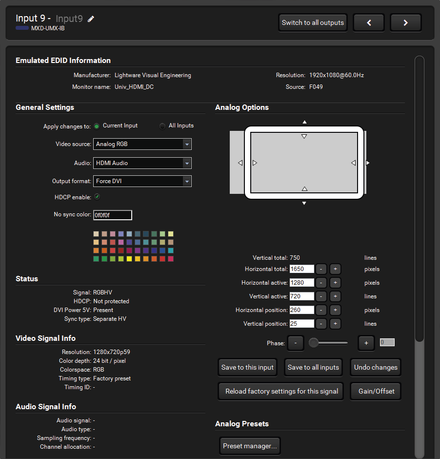
DVI-I Type Input Port Properties (MXD-UMX-IB)
Audio Conversion Mode
The analog stereo and S/PDIF audio ports can be configured as inputs and outputs as well. (The LEDs next to the connectors indicate if the port works as an input or an output to prevent wrong connections.) If they are configured as input, the signal can be used to be embedded into the HDMI stream and/or output on the other audio connector. The available modes:

Audio Conversion Modes
Analog Audio Settings
Analog audio input settings: These settings appear only if the analog audio port is configured as an input. Volume, balance, gain, phase invert and DC filter can be adjusted.
Analog audio output settings: These settings appear only if the analog audio port is configured as an output. Volume, balance, bass, treble, deemphasis, and phase invert can be adjusted.
ATTENTION!The conversion between S/PDIF or HDMI and analog audio is available only with PCM stereo audio signals.
#audio #analogaudio
6.5.3.8. TPS Type Input Port
Supported Boards:
▪MX-TPS-IB, -S, -A, -P, -SP, -AP
▪MX-4TPS2-4HDMI-IB, -A, -S, -P, -AP, SP (only the four TPS ports of the board)
Audio Mode
It can be selected here which audio signal will be embedded in the forwarded HDMI signal. It can be set to ‘(A) No audio’, ‘(B) HDMI audio passthrough’, ‘(C) Embed from aux audio’, ‘(D) Deembed to aux audio’ or ‘(E) HDMI passthrough and deemb to aux audio’. See also the Audio Options section.
TPS Mode Setting
The required mode can be HDBaseT, Longreach, Automatic, RS232 only and RS232+ETH only. For detailed information about the TPS modes, see the TPS Link Modes section. If the PoE is supported by the board, the feature can be enabled/disabled in this section.
Remote Device (valid only for certain extenders)
TPS boards can display the name of the remote Lightware device; it is displayed in the TPS Link section. Click on the Open remote device settings button to open a new window:

Remote Device Properties
Numerous settings and parameters are available on the tabs, like:
▪Changing TCP/IP settings, opening a new LDC window showing the remote device.
▪Changing the crosspoint, Autoselect on/off, showing mute and lock states of the outputs.
▪Terminal window to send LW2 commands.
▪RS-232 port settings of the device's local port.
Firmware Settings
The settings and the update process is described in the Firmware Update of TPS(2) Ports section.
Power over Ethernet (refers only to TPS2 boards)
The PoE-compatible Remote power feature can be enabled port by port under TPS link section and the current state is shown in the following line.
Port Diagrams
ATTENTION!The diagrams of TPS2 ports can be seen on the figures that are almost the same as of TPS ports. The only difference is the remote power feature (12V / 48V).
|
MX-TPS-IB MX-TPS2-IB-P MX-4TPS2-4HDMI-IB* MX-4TPS2-4HDMI-IB-P* Plain TPS input board with remote power support without additional audio ports. |

|
|
MX-TPS-IB-A MX-TPS2-IB-AP MX-4TPS2-4HDMI-IB-A* MX-4TPS2-4HDMI-IB-AP* TPS input board with remote power support and an additional analog audio port. The additional audio port can be used as an input (embedding the analog audio in the video of the TPS signal) or it can be used as an output (de-embedding the audio of the HDMI stream). |

|
|
MX-TPS-IB-S MX-TPS2-IB-SP MX-4TPS2-4HDMI-IB-S* MX-4TPS2-4HDMI-IB-SP* TPS input board with remote power support and an additional S/PDIF audio port. The additional audio port can be used as an input (embedding the digital audio in the video of the TPS signal), or it can be used as an output (de-embedding the audio of the HDMI stream). |

|
* Refers only to the four TPS ports of the board. #audio #analogaudio
For detailed information about the audio settings, see the Audio Options section.

TPS Input Port Properties (MX-TPS2-IB)
6.5.3.9. 3G-SDI Type Input Port
Supported Board:
▪MX-3GSDI-IB

3G-SDI Type Input Port Properties (MX-3GSDI-IB)
Audio Source
The audio source that is embedded in the forwarded HDMI signal can be set.
▪SDI: The audio from the SDI input will be embedded in the forwarded signal.
▪S/PDIF: The audio from the S/PDIF input will be embedded in the forwarded signal.
▪No audio: No audio is embedded in the forwarded signal.
Output Mode
The output signal type can be selected (DVI or HDMI mode) that is sent towards the matrix crosspoint.
▪Audio dependent: Sending HDMI signal to the crosspoint if the audio source is set to embed audio from SDI or S/PDIF.
▪Force HDMI: Always sending HDMI to the crosspoint. If there is no incoming audio on the selected audio source, then silence is embedded in the forwarded signal.
▪Force DVI: Sending only DVI signal to the crosspoint without embedded audio.
▪Frame compatible: Detecting the output board types in the matrix frame and setting the signal type accordingly. If there are only HDMI compatible output boards, then the signal type will be HDMI. If there are one or more DVI output boards in the matrix frame, then the signal type will be DVI. (Note that DVI-HDCP boards are HDMI compliant.)
Input EQ
Long cables have to be equalized on the input port. The Auto setting gives good result in most cases. The 0 dB (disabled) setting switches off equalization.
Video Signal Info
The detected incoming signal resolution and signal type (SD, HD or 3G) is shown. The active mode indicates the signal type that is currently forwarded to the crosspoint (DVI or HDMI).
SDI Audio Channel Allocation
The incoming SDI embedded audio channels can be rearranged and allocated to HDMI audio channels. The channel allocation setups can be saved as presets. SDI audio allocation presets are common for all SDI input ports in the matrix. 3G-SDI signals can have up to 16 audio channels in 4 groups. The input port can work with any 2 groups of the 4.
Presets
There are 4 factory presets for the most common audio channel allocations. Moreover, there are 5 user-configurable presets, which can be renamed as well. To load an audio allocation preset, select the desired preset from the drop-down list and then press Load. The audio channel crosspoint shows the current allocation. To rename a user audio allocation preset, select the desired preset from the drop-down list and then press Rename. Type the new name in the pop-up window and click on OK. Preset names can be up to 5 characters long.
HDMI Audio Channel Allocation
The forwarded HDMI signal has to be set up correctly to indicate the channel allocation. This helps the connected display device or AV receiver to know which audio channels have to be used for which speakers. Select how many audio channels (speakers) have to be used. Then select the desired speaker assignment. These settings define the "outputs" of the audio channel crosspoint below.
Audio Channel Crosspoint
This crosspoint view can be used to set up the channel allocation between the incoming SDI embedded audio and the forwarded HDMI embedded audio. The columns represent the channels of the incoming SDI audio channels. The rows represent the channels of the forwarded HDMI embedded audio. SDI audio channels are highlighted with a yellow background if there is a signal detected.
6.5.4. Output Port Properties
6.5.4.1. DVI-D Type Output Port
Supported Boards:
▪MX-DVID-OB
▪MX-DVI-TP-OB, -OB+

DVI-D Output Port Properties (MX-DVID-OB)
Parameters
The factory default settings give good result in most cases. Please contact Lightware Support (support@lightware.com) for further information if encountering problems with output signals.
6.5.4.2. DVI-DL Type Output Port
Covered board:
▪MX-DVIDL-OB

DVI-DL Type Output Port Properties (MX-DVI-DL-OB)
Output Level
The output signal strength (voltage swing) can be set. The default setting gives good result in most cases.
Pre-emphasis Level
The output signal can be boosted so it may pass-through a longer cable to the display device. The default setting gives good result in most cases.
PLL Bandwidth
The signal is reclocked on the output. The reclocking performance can be adjusted if the signal drops on the display device. The default setting gives good result in most cases.
Dual-Link Mode
The Dual-Link output port can be configured to disable the TMDS wires needed for Dual-Link signals. This can solve problems with Dual-Link monitors when a Single-Link signal is routed to them.
▪Enable Dual-Link: The dual-link channel is enabled disregarding the input port type. Some Dual-Link monitors may display distorted, squeezed picture when the signal comes from a Single-Link input port.
▪Disable Dual-Link: The Dual-Link channel is disabled. In this case, Dual-Link signal is not received. Use this setting if a Single-Link signal has to be routed to the output and the Auto mode does not work.
▪Auto Mode: Enables or disables the Dual-Link channel depending on the input port type. If the input port is Single-Link, then the Dual-Link channel is disabled. If the input port is Dual-Link, then the Dual-Link channel is enabled. Note that only the port type matters, not the signal type on the port.
6.5.4.3. HDMI Type Output Port
Supported Boards:
▪MX-HDMI-OB, MX-DVI-HDCP-OB
▪MX-HDMI-TP-OB, MXD-HDMI-TP-OB
▪MX-CPU2 Preview Output

HDMI Type Output Port Properties (MX-HDMI-OB)
Output Mode
The signal mode can be set to DVI, HDMI 24bit, HDMI 30bit, HDMI 36bit or Auto mode. The Auto option sets the signal mode regarding the attached display device’s EDID and the incoming signal.
Color Range
Some sources may send the video signal with a different color range. If the black or white level seems to be incorrect in the picture, try to set this parameter to compress or expand the color range. The default setting is no change, which gives good result in most cases.
6.5.4.4. HDMI-3D Type Output Port
Supported Boards:
▪MX-HDMI-3D-OB, -A, -S; MX-4TPS2-4HDMI-OB, -A, -S, -P, -AP, -SP (only the four HDMI ports of the board)
▪MX-DVI-4K-OB

HDMI-3D Type Output Port Properties (MX-HDMI-3D-OB-A)
Power 5V Mode #power5v
The DVI or HDMI 5V line can be controlled on an output port with the ‘PWR5V mode’. If it is ‘On’, the 5V DC is always active. If it is ‘Off’, the port never sends the 5V DC.
INFO:If the 5V line is off, sink devices do not send HotPlug signal and their EDIDs will not be read.
The Auto mode means the port gives the 5V, but if the video signal changes (e.g. resolution), it turns off the 5V for 1 sec and turns it on again. This mode is useful for sink devices that are not able to properly handle the changing of the video signal.
Audio Mode
It can be selected here which audio signal will be embedded in the forwarded HDMI signal. It can be set to ‘(A) No audio’, ‘(B) HDMI audio passthrough’, ‘(C) Embed from aux audio’, ‘(D) Deembed to aux audio’ or ‘(E) HDMI passthrough and deemb to aux audio’. For detailed information about the audio settings, see the Audio Options section. #audio
6.5.4.5. DVI-OPT Type Output Port
Supported Boards:
▪MX-DVI-OPT-OB-LC, -SC, -ST
▪MX-DVIDL-OPT-OB-LC, -NT
▪MX-DVI-OPT-OB-R-LC, -NT, -SC, -ST

DVI-OPT Output Port Properties (MX-DVI-OPT-OB-LC)
Laser Enable
The optical module can be powered down with this setting. This can help prevent aging of the laser transmitter. If the laser is disabled, then no signal transmission is available
INFO:The port properties window of MX-DVIDL-OPT-OB boards look the same as above.
6.5.4.6. HDMI-OPT Type Output Port
Supported board:
▪MX-HDMI-OPT-OB-LC, -NT, -SC

HDMI-OPT Type Output Port Properties (MX-HDMI-OPT-OB-SC)
Optical Module Parameters
The connector type is the standard name of the fiber connector that is mounted on the back plate of the board. The connector type can be: LC, SC, ST, and NT (Neutrik OpticalCON).
Laser Enable
The optical module can be powered down with this setting. This can help prevent aging of the laser transmitter. If the laser is disabled, then no signal transmission is available.
6.5.4.7. HDMI-OPT-R Type Output Port
Supported Boards:
▪MX-HDMI-OPT-OB-R-LC, -NT, -SC
Optical Module Parameters
The connector type is the standard name of the fiber connector that is mounted on the back plate of the board. The connector type can be: LC, SC, and NT.
Laser Enable
The optical module can be powered down with this setting. This can help prevent aging of the laser transmitter and save lifetime. If the laser is disabled, then signal is not transmitted.

HDMI-OPT-R Type Output Port Properties (MX-HDMI-OPT-OB-R-SC)
Signal Properties
▪The signal mode can be set to DVI, HDMI or No change mode.
▪The HDCP encryption can be set to Auto or Always.
▪The Audio mode can be set to HDMI audio passthrough or No audio.
6.5.4.8. Audio Type Output Port
Covered board:
▪MX-AUDIO-OB-A #audio #analogaudio #volume

Audio Type Output Port (MX-AUDIO-OB-A)
Plain audio output boards forward audio signals only. The sliders allow to adjust the desired output levels.
6.5.4.9. TPS Type Output Port
Supported Boards:
▪MX-TPS-OB, -S, -A
▪MX-TPS2-OB-P, -AP, -SP
▪MX-4TPS2-4HDMI-OB, -A, -S, -P, -AP, SP (only the four TPS ports of the board)
Port Diagrams #power5v
ATTENTION!The diagrams of TPS2 ports can be seen on the figures that are almost the same as of TPS ports. The only difference is the remote power feature (12V / 48V).
|
MX-TPS-OB MX-TPS2-OB-P Plain TPS output board with remote power support without additional audio ports. |

|
|
MX-TPS-OB-A MX-TPS2-OB-AP TPS output board with remote power support and an additional analog audio port. The additional audio port can be used as an input (embedding the analog audio signal in the video of the TPS signal), or it can be used as an output (de-embedding the audio content of the HDMI stream). |

|
|
MX-TPS-OB-S MX-TPS2-OB-SP TPS output board with remote support and an additional S/PDIF audio port. The additional audio port can be used as an input (embedding the digital audio signal in the video of the TPS signal), or it can be used as an output (de-embedding the audio content of the HDMI stream). |

|
TPS Mode Setting
The required mode can be HDBaseT, Longreach, Automatic, RS232 only and RS232+ETH only. For detailed information about the TPS modes, see the TPS Link Modes section.
Audio Mode #audio #analogaudio
It can be selected here which audio signal will be embedded in the forwarded HDMI signal. It can be set to ‘(A) No audio’, ‘(B) HDMI audio passthrough’, ‘(C) Embed from aux audio’, ‘(D) Deembed to aux audio’ or ‘(E) HDMI passthrough and deemb to aux audio’; see also the Audio Options section.
Power over Ethernet (refers only to TPS2 boards)
The PoE-compatible remote power feature can be enabled on each port individually under TPS link section, and the current state is shown in the following line.
Firmware Settings
The settings and the update process is described in the Firmware Update of TPS(2) Ports section.
Remote Device (valid only for certain extenders)
TPS boards can display the name of the remote Lightware device that is displayed in the TPS Link section. Click on the Open remote device settings button to open a new window:
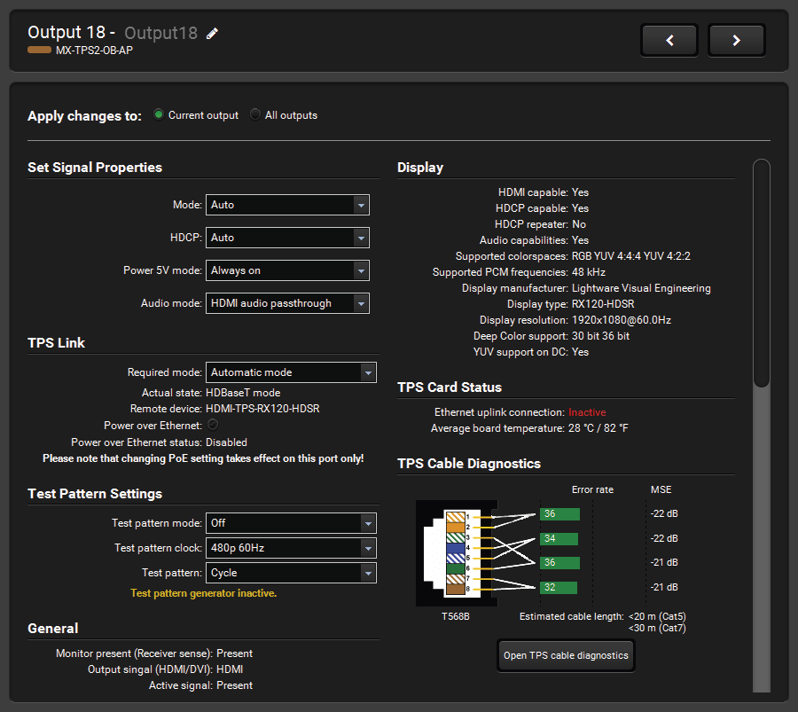
TPS Type Output Port Properties (MX-TPS2-OB-AP)
6.5.5. Presets
Preset operations can be done in the Crosspoint submenu on the Preset tab. Each Lightware matrix router has 32 preset memories that can be loaded and saved at any time. #preset
INFO:A preset setting stores a full configuration of all outputs, so preset loading has an effect on every output, except the locked ones.
A preset can be selected by pressing its button on the left. Preset preview (on the right) will show the crosspoint settings of input and output ports.
Loading a Preset
Step 1.Select the Presets tab from the Crosspoint menu.
Step 2.Select the preset memory (Preset1... Preset32) you want to load.
Step 3.Press the Load button below the Preset preview list. Now the preset is loaded.
Step 4.The new I/O configuration is displayed in Grid view.
Saving a Preset
Step 1.Make the desired crosspoint connections in Tile view or Grid view.
Step 2.Select the preset memory (Preset1...Preset32) where you want to save your current crosspoint connections.
Step 3.Press the Save button below the Preset preview list.
Step 4.A confirmation message is displayed on the information bar; the preset is stored.
Renaming a Preset
Step 1.Select the preset memory (Preset1...Preset32) you want to rename.
Step 2.Type the desired name and press the Rename Preset button; the new name is stored.

The Presets Tab
The Advanced EDID Management is available in the EDID menu. There are two panels: the left one contains Source EDIDs, the right one contains Destination places where the EDIDs can be emulated or copied.
6.6.1. Sources and Destinations
The EDID memory consists of four parts:
▪Factory EDID list shows the pre-programmed EDIDs (F1-F119).
▪Dynamic EDID list shows the display device connected to the device's outputs. The unit stores the last display devices’ EDID on either output, so there is an EDID shown even if there is no display device attached to the output port at the moment.
▪User memory locations (U1 – U12) can be used to save custom EDIDs.
▪Emulated EDID list shows the currently emulated EDID for the inputs. The source column displays the memory location that the current EDID was routed from.

The EDID Menu
The source reads the EDID from the Emulated EDID memory on the INPUT port. Any EDID from any of the User/Factory/Dynamic EDID lists can be copied to the user memory.
There are two types of emulation: static and dynamic.
▪Static EDID emulation: an EDID from the Factory or User EDID list is selected. Thus, the Emulated EDID remains the same until the user emulates another EDID.
▪Dynamic EDID emulation: it can be enabled by selecting D1 or D2 EDID memory. The attached monitor’s EDID is copied to the input; if a new monitor is attached to the output, the emulated EDID changes automatically.
|
|
Exporting an EDID |
|
|
Importing an EDID |
|
|
Displaying the EDID Summary window |
|
|
Opening the Advanced EDID Editor with the selected EDID |
|
|
Opening Easy EDID Creator |
|
|
Executing EDID emulation or copying (Transfer button) |
|
|
Deleting an EDID |
|
|
Selecting all memory places in the right panel |
|
|
Selecting none of the memory places in the right panel |


6.6.2. EDID Operations
Changing the Emulated EDID
Step 1.Choose the desired EDID list (source panel) and select an EDID.
Step 2.Press the Emulated button on the top of the Destination panel.
Step 3.Select the desired ports on the right panel (one or more ports); the EDID(s) will be highlighted in yellow.
Step 4.Press the Transfer button to change the emulated EDID.
Learning an EDID
The process is the same as changing the emulated EDID; the only difference is the Destination panel: press the User button. Thus, one or more EDIDs can be copied into the user memory either from the factory memory or from a connected sink (Dynamic).
Exporting an EDID
ATTENTION!This function is working on Windows and macOS operating systems and under Firefox or Chrome web browsers only.
Source EDID can be downloaded as a file (*.bin, *.dat or *.edid) to the computer.
Step 1.Select the desired EDID from the Source panel (the line will be highlighted in yellow).
Step 2.Press the Save button to open the dialog box and save the file to the computer.
Importing an EDID
Previously saved EDID (*.bin, *.dat or *.edid file) can be uploaded to the user memory:
Step 1.Press the User button on the top of the Source panel and select a memory slot.
Step 2.Press the Upload button below the Source panel.
Step 3.Browse the file in the opening window, then press the Open button. The browsed EDID is imported into the selected User memory.
ATTENTION!The imported EDID overwrites the selected memory place even if it is not empty.
Deleting EDID(s)
The EDID(s) from User memory can be deleted as follows:
Step 1.Press the User button on the top of the Destination panel.
Step 2.Select the desired memory slot(s); one or more can be selected (Select All and Deselect All buttons can be used). The EDID(s) will be highlighted in yellow.
Step 3.Press the Delete selected button to delete the EDID(s).
6.6.3. EDID Summary Window
Select an EDID from the Source panel and press the Info button to display the EDID summary.

EDID Summary Window
6.6.4. Editing an EDID
Select an EDID from the Source panel and press the Edit button to display the Advanced EDID Editor window. The editor can read and write all descriptors that are defined in the standards, including the additional CEA extension. Any EDID from the device’s memory or a saved EDID file can be loaded into the editor.

The EDID Editor Window
The software resolves the raw EDID and displays it as readable information to the user. All descriptors can be edited, saved in an EDID file, or uploaded to the User memory. For more details about EDID Editor, please visit our website (www.lightware.com) and download the EDID Editor user's manual.
Since the Advanced EDID Editor mentioned above needs more complex knowledge about EDID, Lightware introduced a wizard-like interface for fast and easy EDID creation. With Easy EDID Creator, it is possible to create custom EDIDs in four simple steps.

The Easy EDID Creator Window
By clicking on the Create button below Source panel, Easy EDID Creator is opened in a new window. For more details about EDID Editor, please visit our website and download the EDID Editor user's manual: https://lightware.com/pub/media/lightware/filedownloader/file/Application-Note/EDID_Editor_Application_Notes_v2.1.pdf.
6.7. Settings Menu
6.7.1. Configuration Tab
Communication settings are available on this tab.
INFO:The Load default button restores the default network settings in the device. The default network settings can be found in the Factory Default Settings section.
INFO:When the serial port is used for the connection, these settings cannot be changed.
IP Configuration
The IP address and TCP/IP port can be set up here. #ipaddress
Obtain IP Address Automatically #dhcp #network
By selecting the Obtain IP address automatically option, the matrix gets the IP address from the DHCP server on the LAN, or if DHCP server is not present, it gets an AutoIP address from 169.254.xxx.xxx domain. Set BOOTP, DHCP and AutoIP settings according to your network requirements. Always press the Apply settings button to save changes.
Fix IP Configuration
In this case, the connected device has an IP address configuration set up by the user/administrator. Depending on modified settings, you might need to restart the device and the LDC Software. Always press the Apply settings button to save changes.
TCP Port Configuration
Devices can be accessed via this TCP/IP port number with TCP connection. Port number can be modified to any number between 1025 and 65535 except the following: 9999, 14000 - 14009, 30704, and 30718. To use a matrix with Barco Encore, set the port to 23. To use a matrix with Vista Spyder, set the port to 10001. Always press the Apply settings button to save changes.
Serial Port Configuration
The Baud rate for serial connection can be selected from the drop-down list: 9600, 19200, 38400, 57600, or 115200. Always press the Apply settings button to save changes. #rs232 #rs-232 #serial
Date/time Settings
The matrix router has a built-in real time clock on the MX-CPU2 processor board.The date/time code is used for the event log entries.The exact date/time values can be set in this serction. #time

Configuration Tab
6.7.2. Device Information
Basic information about the matrix frame and about the installed boards is listed on this tab:
▪CPU board with controllers
▪Motherboard type and version
▪Input boards with Slot number
▪Output boards with Slot number
6.7.3. Status
The Health status of the matrix frame is displayed on this tab by showing internal measurement values: #firmwareversion
▪CPU Voltage levels
▪Battery cell Voltage level
▪Further internally applied Voltage levels
▪Internal temperature
▪The RPM values of the fans
Press the Refresh button to show/update values.
Battery Low Alert

The warning shows that the battery on the CPU board is exhausted or not inserted. The function of the battery is powering the real time clock when the frame is powered down. The low battery does not affect normal operation of the matrix. However, the error log will not have correct time stamps.
Replacement Steps
Step 1.Switch off the matrix and take out the MX-CPU2 board. Locate the battery holder. Check if the battery is contacting well in the holder.
Step 2.Take the battery out firmly, taking care not to bend the spring contact upwards. Bend the spring contact a little bit downwards to ensure good contact.
Step 3.If the battery is exhausted, replace with lithium button battery type CR2032.

Device Information Tab

Status Tab
6.7.4. Log
Events logged by the device and report generators can be found on Log tab. There are two sections: Report and Log viewer.

The Log Tab
Report Section
ATTENTION!This function is working on Windows and macOS operating systems and under Firefox or Chrome web browsers only. Apple Safari is not supported.
LDC is able to collect information from the device and save it to a report file. This information package can be sent to Lightware support team when a problem may arise with the device:
Step 1.Press the red button: Generate report file.
Step 2.LDC collects the information; this may take up to 5 minutes.
Step 3.After generating the report, a Save as dialog box appears. Select the folder where you want to save the report file. The default file name can be changed.
The report contains the following device-dependent information:
▪Current command protocol,
▪Device type and serial number,
▪Current crosspoint state,
▪Firmware versions of all the internal controllers,
▪Installed I/O board types and versions,
▪Hardware health status,
▪All EDID headers and status (emulated, dynamic, factory, user),
▪Basic error list, log file list and last detailed error log.
Generate Report From File
The LDC is able to send a custom command file to matrix routers. The command file can be generated by Lightware support. This is needed when some special commands have to be used for configuring the device or troubleshooting.
INFO:This function is only for special troubleshooting cases.
Error Log Viewer
Log files saved by the matrix can be downloaded and viewed with this function. The columns in the list are the following: error level, time, error code, error parameter, processor task identifier, occurrences and extra information.
The device creates a new error log file every time it is started, except if a log file exists for that day. The software allows selecting only the months and days that have a log.
Step 1.Select the month of the error log.
Step 2.Select the day.
Step 3.The error log is downloaded and shown as a table.
Step 4.The error log can be saved in a CSV file on the computer by the Export to CSV file button.
There are two viewing modes available:
▪User information: the data is displayed in a structured, user-friendly way; this is the recommended mode.
▪Debug: Raw data display for special troubleshooting cases.
Logs can be deleted one-by-one, or all the logs at the same time with the Delete all logs and Delete this log buttons.
6.7.5. User Preferences
The tab shows some settings in connection with the LDC displaying/working mode. These settings are saved by the LDC and applied next time when the software is started (independently from the type of the matrix):
▪Default crosspoint view (Grid view / Tile view)
▪Default view on Tile view (View mode / Input switch / Output switch)
▪Default Autotake state (On / Off)
▪Confirm Switch All operation (On / Off)

The User Preferences Tab
INFO:The size of the LDC window is also restored from the last run.
This general purpose terminal is intended mainly for testing and debugging purposes. When a successful connection is established with a router, this terminal can be used either via serial RS-232, TCP/IP LAN or USB connection. All commands can be used here that are discussed in the programmer’s reference. The command text can be typed directly.
By default, commands are automatically surrounded by framing brackets. Every sent command and every received response gets an arrow (-> or <-) prefix, and has different font colors in order to help distinguish between them.
The timecode in every row shows the exact time when the command was sent or the response received.
If the Command framing checkbox is unchecked, you can send multiple commands together, however in this case you have to type in the framing brackets manually.
The terminal can be also opened after starting the LDC - press the Terminal button on the Device discovery page on the bottom of the window.
TIPS AND TRICKS:The typed commands can be 'browsed' when the cursor is in the command line and you press the up button on the keyboard. The commands are stored until the LDC is closed.
#terminal

Terminal Window
The user can connect to the matrix through Ethernet, serial port or USB. After establishing the connection, there is no difference between connection types (except some rare cases, which are uniquely noted). Lightware matrix routers can be controlled with external devices that can communicate according to the router protocol. Lightware routers have a special protocol, but to interoperate with third-party devices, a secondary protocol is also provided. The supported LW2 commands are described in this chapter:
7.1. Protocol Description
The protocol description hereinafter stands for Lightware protocol. The commands can be sent to the device in RAW format via the TCP/IP port no. 10001.
The matrix routers accept commands surrounded by curly brackets - { } - and respond data surrounded by round brackets - ( ) - only if a command was successfully executed. All input commands are converted to uppercase, but respond commands can contain upper and lower case letters as well.
7.2. Instructions for the Terminal Application Usage
Terminal Application

The LW2 protocol commands can be applied to the UBEX endpoint devices using a terminal application. You need to install one of them to your control device, for example Putty or CLI. #terminal
Establishing Connection
Follow the steps for establishing connection to the endpoints:
Step 1.Connect the device to a LAN over Ethernet (see the details in the Connecting Steps section).
Step 2.Open the terminal application (e.g. Putty).
Step 3.Add the IP address of the device (default: 192.168.0.100 and the port number (10001).
Step 4.Select the Raw connection type, and open the connection.
Once the terminal window is opened, you can enter the LW2 protocol commands, which are listed in the following sections.
7.2.1. Legend for Control Commands
|
Format |
Explanation |
|
<in> |
Input number in 1- or 2-digit ASCII format (01, 5, 07, 16, etc.) |
|
<out> |
Output number in 1- or 2-digit ASCII format |
|
<in/out> |
Input or output port number in 1- or 2-digit ASCII format * |
|
<in2> |
Input number in 2-digit ASCII format (01, 02, 10, 12 etc.) |
|
<out2> |
Output number in 2-digit ASCII format (01, 02, 10, 12 etc.) |
|
<in2/out2> |
Input or output number in 2-digit ASCII format* |
|
<loc> |
Location number in 1-, 2- or 3-digit ASCII format |
|
<id> |
ID number in 1- or 2-digit ASCII format |
|
<id2> |
ID number in 2-digit ASCII format |
|
CrLf |
Carriage return, Line feed (0x0D, 0x0A) |
|
• |
Space character (0x20) |
|
→ |
Each command issued by the controller |
|
← |
Each response received from the router |
|
<S/C/A> |
Referring to the I/O card specific commands; S: single port, C: all ports of the card, A: all (input or output) ports of the matrix |
* The command has the same arguments on the input ports and the output ports, as well.
7.2.2. Renewed Protocol
The MX-CPU2 processor board works with a similar but renewed protocol as the earlier generation matrix frames with ‘CPU1’. The affected commands that are heavily modified in the MX-CPU2 are marked.
7.2.3. Changing Protocols
The router is equipped with multiple router protocols. Different control interfaces can be set to use different protocols. E.g. the Ethernet interface can use the Lightware protocol while the Serial interface uses Protocol#2 at the same time. The currently used protocol can be viewed or changed any time on the matrix front panel (see the Control Protocols section) or by protocol commands.
7.3. Storage Memories
The matrix stores many configuration settings and parameters and uses different memories. In some cases, it is important to know which setting is stored in which memory.
7.3.1. Matrix Frame Memory
Settings
▪Matrix router serial number
▪HDCP options
▪I/O slot limits
These settings are stored in the matrix frame memory and remain after any board swap – even CPU2 – or any firmware update.
7.3.2. CPU Board Memory
Settings
▪I/O port and preset names
▪EDID lists (F, U, D)
▪EDID emulation table (E)
▪Input and Output port settings
▪Crosspoint settings and Crosspoint presets
▪Serial port settings
▪IP settings
▪Analog video timings
▪Test input multiplexer (FR80)
▪Protocol modes
▪Remote alert send levels
These settings remain unchanged after any firmware update.
Basic error list
This error list is stored in a RAM and it is cleared after every reset or power off. The firmware update process ends with a reset, so the log is lost, but the whole logged data is stored in the SD card, as well.
7.3.3. SD Memory Card (CPU2 Board)
Settings: Detailed error list
Error log helps the support team if there is any dysfunction. CPU2 board stores the error log with time stamps.
7.3.4. Input and Output Board Memory
Settings: Manufacturing parameters
An input or output board can store the manufacturing parameters regarding only the board that contains them.
7.4. Switching and Control Commands
7.4.1. Test Input and Preview Output
MX-FR80R and MX-FR80R
Used in the MX-FR80R or MX-FR65R router frame, the Preview output is directly connected to the 80th output port with a DVI splitter. Therefore this port always outputs the same signal as the 80th output, even if it has a different interface (TP, OPT, etc.). The 80th input port of the crosspoint is multiplexed between the Test input port and the 8th port of the 10th input card. This switch is independent from the crosspoint state. The selected port (Test input or Input board #10) will be available as the 80th input on the crosspoint switch.
Other Frames
All other frames use the Test input and Preview output just like any other ports. These ports are referred to as the last port in the crosspoint.
|
Frame |
Test input |
Preview output |
|
MX-FR9, MX-FR9R |
in 9 |
out 9 |
|
MX-FR17, MX-FR17R |
in 17 |
out 17 |
|
MX-FR33L, MX-FR33R |
in 33 |
out 33 |
|
MX-FR65R |
in 80 |
out 80 |
|
MX-FR80R |
multiplexed in 80 |
distributed out 80 |
7.4.2. Selecting the 80th Input Port (MX-FR80R)
DIFFERENCE:This function has been heavily modified in MX-CPU2 compared to CPU1.
Configure the 80th port to use the Test input port or the 8th port of the 10th input card. The status of the multiplexer is not shown in other crosspoint commands. The crosspoint switching works independently from this setting.
Command and Response
»{TI=<value>}
«(TI=<value>)CrLf
Parameters
|
Identifier |
Parameter description |
Parameter values |
|
<value> |
Test input configuration |
?: Query 80th port multiplexer status 0: Set port multiplexer to use the 8th port of the 10th input card. 1: Set port multiplexer to use the Test input port. |
Example
»{ti=?}
«(TI=1)CrLf
The test input is selected for the 80th input of crosspoint. The last port on the 10th input board is not used.
7.4.3. Switching an Input to an Output
Command and Response 1# #switch
»{<in>@<out>}
«(O<out2>•I<in2>)CrLf
Example
»{1@5}
«(O05 I01)CrLf
Input 1 is switched to Output 5.
Command and Response 2#
»{<in>@<out>}
«(1LO<out2>)CrLf
Example
»{2@4}
«(1LO04)CrLf
Input 2 to Output 4 switch is not made because Output 4 is locked.
ATTENTION!The response for this command does not show whether the output is muted. To check the mute status, a separate query has to be used, like {VC}; see the Displaying the Current Connection States of the Outputs section.
INFO:To achieve multiple switches executed together, see the Batch Switch Outputs section.
7.4.4. Switching an Input to All Outputs
Command and Response
»{<in>@O}
«(I<in2>•ALL)CrLf
Example
»{02@O}
«(I02 ALL)CrLf
Input 2 is switched to all outputs.
INFO:The response for this command does not show whether any of the outputs are muted. To check the mute status, a separate query has to be used.
INFO:The response does not show if there were some locked outputs that could not be switched.
This command switches all outputs to the same numbered inputs. Output 1 will be switched to the Input 1, Output 2 to Input 2, etc.
Command and Response
»{<in>@D}
«(ALL•<out2>•out2>•…•<out2>•<out2>)CrLf
Example
»{1@d}
«(ALL 01 02 03 04 05 06 07 08 09 10 11 12 13 14 15 16 17)CrLf
The example shows how to connect video outputs to the same numbered inputs. The response contains all the connections.
DIFFERENCE:This function has been heavily modified in MX-CPU2 compared to CPU1.
The router is capable of switching multiple outputs exactly at the same time. To do this, the normal switch commands have to be used. If the switch commands arrive at the router with less than 10 milliseconds delay, then the router collects the commands and changes the output connections together.
Required circumstances
▪Switch commands have this format: {<in>@<out>}{<in>@<out>}.
▪The delay between two ‘}’ characters must be below 10 milliseconds.
▪No other command or junk character is allowed between switch commands.
▪Affected outputs must not be locked.
If any of the above circumstances fail, then the commands will be processed separately and the output connections will change one by one.
ATTENTION!The delay timeout applies for the receiving time of characters. Please note that if LAN connection is used, then the network may cause additional delays. This could result in batch switching not occuring.
The example below shows a command that resulted in batch switching:
One by one commands
»{02@01}
«(O01 I02)CrLf
»{05@04}
«(O04 I05)CrLf
Batch commands
»{02@01}{05@04}
«(O01 I02)CrLf
«(O04 I05)CrLf
The example below shows a command that did not result in batch switching, because another command has been inserted:
One by one commands
»{02@01}
«(O01 I02)CrLf
»{+06}
«(0MT06)CrLf
»{05@04}
«(O04 I05)CrLf
Batch commands
»{02@01}{+06}{05@04}
«(O01 I02)CrLf
«(0MT06)CrLf
«(O04 I05)CrLf
INFO:The response does not show if batch switching happened or not. This ensures that a third party controller does not get unknown responses.
7.4.7. Displaying the Current Connection States of the Outputs
DIFFERENCE:This function has been heavily modified in MX-CPU2 compared to CPU1.
Viewing all outputs’ connection results in different response lengths, because it depends on the frame size. The response below supposes a router having 17 outputs.
INFO:The MX-CPU2 responds the connection of Preview Output port as well. The earlier 16x16 or 32x32 frames responded 16 and 32 outputs, but with MX-CPU2 the response will be 17 and 33 correspondingly.
Command and Response #crosspoint
»{VC}
«(ALL•<O1>•<O2>•<O3>•<O4>•<O5>•<O6>•<O7>•<O8>•<O9>)CrLf
Example #1 (MX-FR9)
»{vc}
«(ALL 02 02 02 05 05 05 08 08 08)CrLf
Parameters
All <Ox> indexes show the corresponding output’s connection state. If value <O5> equals 04, it means that Output 5 is connected to Input 4. All <Ox> indexes are two digit ASCII characters (01, 02, 04, etc.).
Explanation
Viewing connection for all outputs. Input 2 is connected to Outputs 1, 2 and 3. Input 5 is connected to Outputs 4, 5 and 6. Input 8 is connected to Outputs 7 through 17.
INFO:If an output is locked, muted, or both locked and muted, the response format changes. If outputs are muted, you get a letter 'M', if locked, a letter 'L' and if muted and locked at the same time, 'U' before the 2 digit numbers.
Example #2 (MX-FR17)
»{vc}
«(ALL M02 L02 U02 05 05 05 08 08 08 08 08 08 08 08 08 08 08)CrLf
Parameters
Any <Ox> indexes can be a two digit number, or there can be a leading character showing the mute and/or lock state for the corresponding output.
|
Identifier |
Parameter description |
Parameter values |
|
<Ox> |
Output port number |
<in2>: <Ox> is connected to <in2>, <Ox> neither muted nor locked. M<in2>: <Ox> is connected to <in2>, <Ox> is muted, and unlocked. L<in2>: <Ox> is connected to <in2>, <Ox> is not muted, but locked. U<in2>: <Ox> is connected to <in2>, <Ox> is muted and locked. |
Explanation
Viewing connection for all outputs. Input 2 is connected to Outputs 1, 2 and 3. Output 1 is muted. Output 2 is locked. Output 3 is muted and locked. Input 5 is connected to Outputs 4, 5 and 6. Input 8 is connected to Outputs 7 through 16.
7.4.8. Listing the Mute/Unmute States of All Outputs
ATTENTION!The response length depends on the frame size.
Command and Response (MX-FR9)
»{VM}
«(MUT•<M1>•<M2>•<M3>•<M4>•<M5>•<M6>•<M7>•<M8>•<M9>)CrLf
Parameters
All <Mx> indexes are one digit numbers, showing the mute state for the corresponding output. If <Mx> equals 0, the output x is unmuted. If <Mx> equals 1, the output x is muted.
Example (MX-FR9)
»{vm}
«(MUT 1 0 1 1 0 0 0 0 0)CrLf
Output 1, 3 and 4 are muted, the other outputs are not muted.
7.4.9. Muting a Specified Output
Mute output <out>. The output signal is turned off. #mute
Command and Response
»{#<out>}
«(1MT<out2>)CrLf
Example
»{#03}
«(1MT03)CrLf
Output 3 is muted. No signal is present on Output 3 now.
INFO:Muting does not change the crosspoint’s state, but disables the output itself. This way the last connection can be easily restored with an unmute command.
INFO:Switching a muted output does not unmute the output.
7.4.10. Unmuting a Specified Output
Command and Response #unmute
»{+<out>}
«(0MT<out2>)CrLf
Example
»{+03}
«(0MT03)CrLf
Output 3 is unmuted. Now Output 3 is switched to the input it was connected to prior to the mute command.
ATTENTION!Unmuting an output makes the previous connection active, as the crosspoint’s state has not been changed with the muting command, only the output was disabled.
7.4.11. Disconnecting an Output
Switch an output to a virtual unconnected input. No signal on the output.
Command and Response
»{0@<out>}
«(O<out2>•I00)CrLf
Example
»{0@5}
«(O05 I00)CrLf
Output 5 is disconnected from the inputs (no input will be connected). Disconnecting acts similar to muting, except that the previous connection cannot be restored with an unmute command. A disconnected output can still be muted or unmuted, however, this has no real effect in this case. To make a disconnected output live again, another input has to be switched to it.
INFO:The response for this command is (1LO<out2>) if the output is locked.
7.4.12. Disconnecting All Outputs
Switching all the outputs to a virtual unconnected input. No signal on any output.
Command and Response
»{0@O}
«(I00 ALL)CrLf
Example
»{0@O}
«(I00 ALL)CrLf
The outputs are disconnected from the inputs (no input will be connected). Disconnecting acts similar to muting, except that the previous connection cannot be restored with an unmute command. A disconnected output can still be muted or unmuted, however, this has no real effect in this case. To make a disconnected output live again, another input has to be switched to it.
7.4.13. Locking a Specified Output
Lock output <out>. Output’s state cannot be changed until unlocking. #lock
Command and Response
»{#><out>}
«(1LO<out2>)CrLf
Example
»{#>05}
«(1LO05)CrLf
Output 5 is locked.
7.4.14. Unlocking a Specified Output
Unlock output <out>. The connection on output can be changed.
Command and Response #unlock
»{+<<out>}
«(0LO<out2>)CrLf
Example
»{+<03}
«(0LO03)CrLf
Output 5 is unlocked.
INFO:The router issues the response above regardless of the previous state of the output (whether it was locked or unlocked).
Save current crosspoint configuration (output states) to preset <id>. All frames have 32 preset memories.
Command and Response #preset
»{$<id>}
«(SPR<id2>)CrLf
Example
»{$4}
«(SPR04)CrLf
Current crosspoint state is saved to Preset 4, including the mute state of the outputs.
ATTENTION!Lock states are not saved. Lock state is assigned to the physical output of the router. Presets do not affect output locks.
Load crosspoint configuration from preset <id>.
Command and Response
»{%<id>}
«(LPR<id2>)CrLf
Example
»{%4}
«(LPR04)CrLf
Current crosspoint state is changed according to Preset 4, including the mute state of the outputs.
INFO:Locked outputs are left unchanged. Presets do not affect output locks.
The peview of the stored preset <id> without loading it. The response depends on the crosspoint size.
Command and Response
»{VP#<id>=?}
«(VP#<id>=•<O1>•<O2>•<O3>•<O4>•<O5>•<O6>•<O7>•<O8>•<O9>)CrLf
Parameters
|
Identifier |
Parameter description |
Parameter values |
|
<Ox> |
Output port number |
<in2>: <Ox> is connected to <in2>, <Ox> is not muted. M<in2>: <Ox> is connected to <in2>, <Ox> is muted. |
Example
»{vp#3=?}
«(VP#3= 02 M02 M01 02 02 01 01 01 01)CrLf
Viewing connections for Preset 3. Input 2 is connected to Outputs 1, 2, 4 and 5. Input 1 is connected to all other outputs. Outputs 2 and 3 are muted.
Command and Response
»{PNAME#<id>= <preset_name>}
«(PNAME#<id>= <preset_name>)CrLf
Example
»{pname#1=First preset}
«(PNAME#1=First preset)CrLf
Preset 1 was named as 'First preset'.
Command and Response
»{INAME#<in>=<input_name>}
«(INAME#<in>=<input_name>)CrLf
Example
»{iname#3=Media_Player}
«(INAME#3=Media_Player)CrLf
Input 3 was named as 'Media_Player'.
Command and Response
»{ONAME#<out>=<output_name>}
«(ONAME#<out>=<output_name>)CrLf
Example
»{oname#2=Monitor#2}
«(ONAME#2=Monitor#2)CrLf
Output 2 was named as 'Monitor#2'.
7.4.21. Querying the Name of a Preset
Command and Response #preset
»{PNAME#<id>=?}
«(PNAME#<id>= <preset_name>)CrLf
Example
»{pname#1=?}
«(PNAME#1=First_preset)CrLf
Name for Preset 1 is 'First_preset'.
7.4.22. Querying the Name of an Input
Command and Response
»{INAME#<in>=?}
«(INAME#<in>=<Input_name>)CrLf
Example
»{iname#1=?}
«(INAME#1=PC_1)CrLf
Name for Input 1 is 'PC_1'.
7.4.23. Querying the Name of an Output
Command and Response
»{ONAME#<out>=?}
«(ONAME#<out>=<output_name>)CrLf
Example
»{oname#2=?}
«(ONAME#2=Monitor_2)CrLf
Name for Output 1 is 'Monitor_2'.
7.4.24. Reloading the Default Preset Names
ATTENTION!The <id> field is not relevant here, it only needs to be a valid one. The command will affect ALL presets, disregarding the actual number that was in the command.
Command and Response
»{PNAME#<id>=!}
«(PNAME#<id>=Preset•<id>)CrLf
Example
»{pname#2=!}
«(PNAME#2=Preset 2)CrLf
All preset names are set to default: 'Preset 1', 'Preset 2', and so on.
7.4.25. Reloading the Default Input Names
ATTENTION!The <id> field is not relevant here, it only needs to be a valid one. The command will affect ALL inputs, disregarding the actual number that was in the command.
Command and Response
»{INAME#<id>=!}
«(INAME#<id>=Input•<id>)CrLf
Example
»{iname#4=!}
«(INAME#4=Input 4)CrLf
All input names are set to default: 'Input 1', 'Input 2', and so on.
7.4.26. Reloading the Default Output Names
ATTENTION!The <id> field is not relevant here, it only needs to be a valid one. The command will affect ALL outputs, disregarding the actual number that was in the command.
Command and Response
»{ONAME#<id>=!}
«(ONAME#<id>=Output•<id>)CrLf
Example
»{oname#3=!}
«(ONAME#3=Output 3)CrLf
All output names are set to default: 'Output 1', 'Output 2', and so on.
7.5. Communication Setup Commands
7.5.1. Querying the IP Settings
DIFFERENCE:This function has been heavily modified in MX-CPU2 compared to CPU1.
The TCP/IP settings can be retrieved from the router with this command.
Command and Response #ipaddress #network
»{IP_CONFIG=?}
«(IP_CONFIG=<id>•<ip_address>•<port>•<mask>•<gateway>)CrLf
Parameters
|
Identifier |
Parameter description |
Default value |
|
<id> |
0: fix IP 2: DHCP |
0 |
|
<ip_address> |
IP address |
192.168.254.254 |
|
<port> |
TCP/IP port |
10001 |
|
<mask> |
Subnet mask |
255.255.0.0 |
|
<gateway> |
Gateway address |
0.0.0.0 |
Example
»{ip_config=?}
«(IP_CONFIG=0 192.168.2.106 10001 255.255.000.000 192.168.002.001)CrLf
The router has a fix IP address 192.168.2.106 on the 255.255.0.0 subnet with a gateway on 192.168.2.1 and communicates over TCP port 10001.
7.5.2. Reloading the Default IP Settings
This command sets the router to the factory default IP setup.
Command and Response
»{IP_CONFIG=!}
«(Changing•IP• configuration…)CrLf
«(DONE!)CrLf or
«(FAILED!)CrLf
Parameters
After a successful command execution:
|
Parameter |
Default value |
|
IP address |
192.168.254.254 |
|
TCP/IP port |
10001 |
|
Subnet mask |
255.255.0.0 |
|
Gateway address |
0.0.0.0 |
Example
»{ip_config=!}
«(Changing IP configuration…)CrLf
«(DONE!)CrLf
INFO:This command can be used on all control interfaces (LAN, RS-232, and USB), but the ‘(DONE!)’ response cannot be seen on LAN, because the connection is dropped just after the ‘(Changing IP configuration…)’ response.
INFO:Factory default setting can be reloaded by the front panel buttons (IP Settings section) or via the front panel LCD menu.
7.5.3. Setting a Dynamic IP Address (DHCP)
After sending this command, the router will request an IP address from the DHCP. #dhcp
Command and Response
»{IP_CONFIG=D}
«(Changing•IP• configuration…)CrLf
«(DONE!)CrLf or
«(FAILED!)CrLf
Parameters
After a successful command execution:
|
Parameter |
Value |
|
IP address |
Acquired with DHCP |
|
TCP/IP port |
Unchanged |
|
Subnet mask |
Acquired with DHCP |
|
Gateway address |
Acquired with DHCP |
Example
»{ip_config=D}
«(Changing IP configuration…)CrLf
«(DONE!)CrLf
INFO:This command can be used on all control interfaces (LAN, RS-232, and USB), but the ‘(DONE!)’ response cannot be seen on LAN, because the connection is dropped just after the ‘(Changing IP configuration…)’ response.
INFO:DHCP setting can be reloaded by the front panel buttons as well or via the front panel LCD menu.
7.5.4. Querying the RS-232 Baud Rate
The RS-232 baud rate can be checked. It works via LAN and RS-232 as well, but if RS-232 is used, the command has to be sent with the appropriate baud rate.
Command and Response #rs-232 #rs232 #serial
»{RS232BAUD=?}
«(RS232BAUD=<rate>)CrLf
Example
»{rs232baud=?}
«(RS232BAUD=57600)CrLf
The router communicates with 57600 baud on the RS-232 port.
INFO:RS-232 Baud rate can be checked and set on the front panel LCD menu as well.
7.5.5. Changing the RS-232 Baud Rate
DIFFERENCE:This function has been heavily modified in MX-CPU2 compared to CPU1.
The RS-232 baud rate can be set. If the RS-232 connection is used, the command has to be sent with the earlier baud rate, but the response comes with the new baud rate.
Command and Response
»{RS232BAUD=<rate>}
«(RS232BAUD=<rate>)CrLf
Parameters
The possible values of <rate>: 9600, 19200, 38400, 57600 (default), 115200.
Example
»{rs232baud=9600}
«(RS232BAUD=9600)CrLf
INFO:RS-232 Baud rate can be checked and set on the front panel LCD menu as well.
7.5.6. Querying the Control Protocol
DIFFERENCE:This function has been heavily modified in MX-CPU2 compared to CPU1.
Matrix routers can be controlled with different control protocols. This command queries the active protocol for the used control interface.
ATTENTION!Be aware that different control interfaces can be set to use different protocols. E.g. the Ethernet interface can use the Lightware protocol while the Serial interface uses Protocol#2 at the same time.
Command and Response
»{P_?}
«(CURRENT•PROTOCOL•=•#<protocol>)CrLf
Parameters
|
Identifier |
Parameter description |
Parameter values |
|
<protocol> |
Currently active protocol |
1: Lightware (default) 2: Protocol #2 3: LW simple (not in use) |
Example
»{p_?}
«(CURRENT PROTOCOL = #1)CrLf
The matrix communicates with Lightware protocol.
The response shows only the active protocol for the interface that was used to send the command. Control protocol for each interface can be checked with the front panel buttons (see the Control Protocols section) or in the front panel LCD menu.
7.5.7. Changing the Control Protocol
DIFFERENCE:This function has been heavily modified in MX-CPU2 compared to CPU1.
Matrix routers can be controlled with different control protocols. This command sets the active protocol only for the currently used control interface. The setting applies only to the interface that was used to send the command! The USB interface always uses the Lightware protocol, this cannot be changed.
Command and Response
»{P_<protocol>}
«(PROTOCOL•#<protocol>•SELECTED!)CrLf
Parameters
|
Identifier |
Parameter description |
Parameter values |
|
<protocol> |
Currently active protocol |
1: Lightware (default) 2: Protocol #2 3: LW simple (not in use) |
Example
»{p_1}
«(PROTOCOL #1 SELECTED!)CrLf
The matrix communicates with Lightware protocol.
INFO:Be aware that different control interfaces can be set to use different protocols. E.g. the Ethernet interface can use the Lightware protocol while the Serial interface uses Protocol#2 at the same time.
INFO:The Control protocol can be checked with the front panel buttons or in the front panel LCD menu.
7.5.8. Configure Remote Alerts
DIFFERENCE:This function has been heavily modified in MX-CPU2 compared to CPU1.
The matrix logs different levels of errors. Configure which level of errors has to be sent out as an alarm message. The matrix will send an immediate message on all control interfaces when a ‘matter’, ‘error’ or ‘fatal’ level error occurs.
Command and Response
»{ELEVELSEND#<p>= <0>;<1>;<2>;<3>;<4>}
«(ELEVELSEND#<p>= <0>;<1>;<2>;<3>;<4>)CrLf
Parameters
|
Identifier |
Parameter description |
Parameter values |
|
<p> |
Adjusted control interface |
0 = all 1 = RS-232 2 = LAN 3 = USB |
|
<0> |
'Notice' level events |
0 = no immediate message sent |
|
<1> |
'Warning' level events |
|
|
<2> |
'Matter' level events |
|
|
<3> |
'Error' level events |
|
|
<4> |
'Fatal' level events |
See the Error Responses section for more information about error levels.
Example
»{elevelsend#0=0;0;1;1;1}
«(ELEVELSEND#0=0;0;1;1;1)CrLf
7.6.1. Querying the Product Type
DIFFERENCE:This function has been heavily modified in MX-CPU2 compared to CPU1.
Command and Response #label #devicelabel
»{I}
«(<PRODUCT_TYPE>)CrLf
Example
»{i}
«(I: MX-FR17)CrLf
INFO:Please note that MX-FR65R gives (I:MX-FR80R) response.
7.6.2. Querying the Serial Number
The device responds its 8-digit serial number.
Command and Response
»{S}
«(SN:<SERIAL_NO>)CrLf
Example
»{s}
«(SN:3C019935)CrLf
7.6.3. Querying the Firmware Version of the CPU
View the CPU firmware revision. To view other controllers' firmware version, see the {FC} command.
Command and Response
»{F}
«(FW:<FW_VER><s>)CrLf
Example
»{f}
«(FW:3.4.9r)CrLf
<FW_VER> is the firmware version. It is followed by <s> string, which may indicate special versions. <s>=r indicates standard version.
7.6.4. Querying the CPU Firmware Compile Time
Command and Response
»{CT}
«(Compiled:<DATE>•<TIME>•Build:<tag>)CrLf
Parameters
|
Identifier |
Parameter description |
|
<DATE> |
Month, day and year |
|
<TIME> |
Hours, minutes and seconds |
|
<tag> |
Identification number of the firmware |
Example
»{ct}
«(Compiled:May 10 2012 16:36:35 Build:3564)CrLf
7.6.5. Querying the Crosspoint Size
The response shows the physical crosspoint size.
Command and Response
»{GETSIZE}
«(SIZE=<size>)CrLf
Parameters
<size> parameter can be 17x17, 33x33 or 80x80.
Example
»{getsize}
«(SIZE=17x17)CrLf
7.6.6. Querying the Number of the Allowed I/O Slots
Checking the allowed number of I/O boards.
Command and Response
»{MAXSLOTS=?}
«(MAXSLOTS= IB:<num1>,OB:<num2>)CrLf
Parameters
<num1> and <num2> are two-digit numbers showing the maximum number of allowed input and output boards correspondingly.
Example
»{maxslots=?}
«(MAXSLOTS=IB:01,OB:01)CrLf
The router is limited to one input board and one output board (MX-FR9).
7.6.7. Querying the Installed I/O Boards
DIFFERENCE:This function has been heavily modified in MX-CPU2 compared to CPU1.
Shows the hardware name and revision of the installed cards. The number of responses varies according to the frame size (number of slots).
Command and Response
»{IS}
«(SL#•0•<MB_DESC>)CrLf
«(SL#•1•<OB_DESC>)CrLf
«(SL#•2•<OB_DESC>)CrLf
...
«(SL#•51•<IB_DESC>)CrLf
«(SL#•52•<IB_DESC>)CrLf
...
«(SL•END)CrLf
Parameters
Slot 0 represents the motherboard. Slots from 1 to 50 are showing the output boards. Slots from 51 to 100 are showing the input boards.
|
Identifier |
Parameter description |
|
SL# 0 |
This 'slot' represents the motherboard. |
|
SL# 1-50 |
Slots from 1 to 50 are showing the output boards. |
|
SL# 51-100 |
Slots from 51 to 100 are showing the input boards. |
|
SL END |
This message indicates the end of the list. |
INFO:The device responds an ‘empty’ board descriptor for empty physical slots.
Example
»{is}
«(SL# 0 MX-DVI-MB80 SCH_1.1 PCB_1.1)CrLf
«(SL# 1 MX-DVID-OB SCH_2.0 PCB_2.0)CrLf
«(SL# 2 empty)CrLf
…
«(SL# 51 MX-DVID-IB SCH_2.0 PCB_2.0)CrLf
The router reports that it has two output and two input slots. There are two input cards and one output card installed, and one output slot is empty.
7.6.8. Querying the Firmware of All Controllers’
Shows the firmware versions of all installed controllers. The response depends on the router configuration.
Command and Response
»{FC}
«(CF•<DESC>)CrLf
«(CF•<DESC>)CrLf
…
«(CF END)CrLf
Example
»{fc}
«(CF MX-CPU2 FW:3.4.9r SCH_2.2)CrLf
«(CF MX-CP FW:1.0.8 @ 0x10)CrLf
…
«(CF END) CrLf
The matrix has an MX-CPU2 processor. There is a control panel in the frame.
7.6.9. Querying the LAN Versions
Shows information about the LAN interface.
Command and Response
»{LAN_VER=?}
«(MAC_ADDR=<mac>)CrLf
«(WEB_VER=<ver1>)CrLf
«(SERVER_VER=<ver2>)CrLf
Example
»{lan_ver=?}
«(MAC_ADDR=00-20-4A-C7-AC-C0)CrLf
«(WEB_VER=1.7.2)CrLf
«(SERVER_VER=4.0.0)CrLf
Parameters
|
Identifier |
Parameter description |
|
<mac> |
MAC address of LAN controller in the matrix. |
|
<ver1> |
Version of built-in website user interface (webcontent). |
|
<ver2> |
Version of LAN controller firmware (webserver). |
MAC address, webcontent and webserver versions are shown.
7.6.10. Querying the Health Status
Command and Response
»{ST}
«(ST•<DESC>)CrLf
…
«(ST•<DESC>)CrLf
Example (MX-FR17R) #power
»{st}
«(ST CPU 3.32V 5.03V 3.05V 5.03V 12.11V 31.6C)CrLf
«(ST FAN#1 1530RPM)CrLf
«(ST FAN#2 1530RPM)CrLf
«(ST PS#1=OK)CrLf
«(ST PS#2=OK)CrLf
The response depends on the frame type. Internal voltages, temperature and fan speeds are shown. The last two rows show the status of the redundant PSUs.
7.6.11. Querying the Error List
DIFFERENCE:This function has been heavily modified in MX-CPU2 compared to CPU1.
Shows the basic error list since last boot up.
Command and Response
»{ELIST=?}
«(ELIST#<num>•<elevel>•<code>•<param>•<occ>)CrLf
«…
«(ELIST#<num>•<elevel>•<code>•<param>•<occ>)CrLf
Parameters
|
Identifier |
Parameter description |
Parameter values |
|
<num> |
Line number |
|
|
<elevel> |
The level of the error |
NOTICE: Not an error, Initialization information WARNING: Possible problem without influencing normal operation MATTER: Problem that may lead to further errors ERROR: Serious error, must report to Lightware support FATAL: Fatal error, normal operation is not possible |
|
<code> |
Short name for type of log entry |
|
|
<param> |
Technical parameter |
|
|
<occ> |
Occurence number for this type of log entry |
Example
»{elist=?}
«(ELIST#1 Notice BOOT p:2 o:1)CrLf
«(ELIST#2 Notice SERIAL p:0 o:1 )CrLf
«(ELIST#3 Notice CARDINIT p:81 o:1 ) CrLf
«(ELIST#4 Notice CARDINIT p:2 o:1 )CrLf
«(ELIST#5 Notice READY p:0 o:1)CrLf
There are no errors, only standard notices that occur upon boot up.
INFO:The error list can contain NOTICEs and WARNINGs under normal operation. These entries do not mean that there is any problem with the matrix!
The matrix router can be restarted without unplugging power.
Command and Respons #reset #restart
»{RST}
«(Booting…)CrLf
«(<name>•Ready!)CrLf
Parameters
The matrix reboots and sends a message when it is ready. <name> is the type of the matrix.
Example
»{rst}
«(Booting…)CrLf
«(MX-FR17 Ready!)CrLf
INFO:The response can be seen only if the connection to the router is still alive.
The matrix router has a built-in real time clock on the MX-CPU2 processor board. This command allows reading the CPU time. #date #time
Command and Response
»{GETTIME}
«(<date>•<time>•UTC+<zone>)CrLf
Parameters
See the next section.
Example
»{gettime}
«(04.10.2016. 16:52:34 UTC+0100)CrLf
This command allows setting the built-in real time clock on the CPU2 board.
Command and Response
»{SETTIME=<date>•<time>•UTC+<zone>}
«(<date>•<time>•UTC+<zone>)CrLf
Parameters
The UTC, and therefore the processor time do not observe daylight saving. E.g., the Central European Time is UTC+1 during winter and UTC+2 during summer. The CPU time is used mainly as a timestamp in the error log.
|
Identifier |
Parameter description |
|
<date> |
Date in DD.MM.YYYY. format |
|
<time> |
Time in HH:MM:SS format |
|
<zone> |
Time zone related to UTC (Universal Coordinated Time) in HHMM format. |
Example
»{settime=15.10.2012. 16:52:34 UTC+0100}
«(15.10.2012. 16:52:34 UTC+0100)CrLf
INFO:The MX-CPU2 board has a CR2032 button battery, which supplies power to the clock when the matrix is not powered on.
7.7.4. Switching the Matrix to Standby
DIFFERENCE:This command works only in the MX-FR80R and MX-FR65R. The frame can be switched to standby without unplugging the power. The CPU can still communicate.
Command and Response
»{PWR_<state>}
«(Powered <state>)CrLf
Parameters
The <state> parameter can be OFF or ON.
Example
»{pwr_off}
«(Powered off)CrLf
INFO:The I/O boards do not get any power when in standby mode. The CPU will still work and respond only for status commands.
7.7.5. Reloading the Factory Default Values and Settings
DIFFERENCE:This function has been heavily modified in MX-CPU2 compared to CPU1.
Factory default settings can be reloaded for different functions separately. Multiple functions can be entered.
Command and Response
»{FACTORY=<f1>;<f2>;…;<fx>}
«(FACTORY•<f1>…)CrLf
«(FACTORY•<f2>…)CrLf
«…
«(FACTORY•<fx>…)CrLf
Parameters
<f1>, <f2> are the names of the functions that need to be reset to factory default. Any number of <fx> can be entered, separated by semicolons.
|
<fx> |
Restores factory settings to |
Additional response |
|
GENERAL |
Control protocols, Front panel state, Alarm message levels |
none |
|
IOCARDS |
All I/O settings for boards currently in the frame |
none |
|
XPOINT |
Crosspoint table and configuration (All outputs to in1, unmute, unlock) |
none |
|
PRESETS |
Crosspoint presets (All output to in1, unmuted) and preset names |
(PNAME#1=Preset1) (I1 ALL) (SPR01)…(SPR32) |
|
IONAMES |
Input and output names |
(INAME#1=Input1) (ONAME#1=Output1) |
|
EDIDS |
Emulated EDIDs (F49 is default) |
none |
|
EDIDMEM |
Clear User and Dynamic EDIDs |
(DE_OK) (DE_OK) |
|
ALL |
Restores all of the factory settings listed above |
as above |
Example
»{factory=xpoint;iocards;edids}
«(FACTORY XPOINT…)CrLf
«(FACTORY IOCARDS…)CrLf
«(FACTORY EDIDS…)CrLf
Factory default settings are reloaded for crosspoint and I/O card configurations and emulated EDIDs. The response may contain additional messages as the router makes the configurations. These responses can be omitted.
INFO:After resetting the needed parameters, the matrix restarts.
DIFFERENCE:These functions have been heavily modified in MX-CPU2 compared to CPU1.
The EDID router manipulates the EDID memory, which has memory locations that are assigned to specific input or output ports. Please read The EDID Memory of a Matrix section about the EDID memory structure.
7.8.1. Changing the EDID on an Input Port
Copy an EDID from memory location <source> to input port <destination>. #edid
Command and Response
»{<destination>:<source>}
«(E_SW_OK)CrLf
…delay…
«(E_S_C)CrLf
Parameters
|
Identifier |
Parameter description |
Parameter values |
|
<destination> |
Emulated EDID memory slot |
E01-E80 * |
|
<source> |
Source EDID memory slot |
F01-F119: Factory preset EDIDs U01-U50: User saved EDIDs D01-D80: Dynamic EDIDs of connected sinks * |
* the highest value depends on the frame size.
If <source> is ‘Fxx’ or ‘Uxx’, then static EDID routing occurs. In this case, the router will keep the same EDID on the input until it is changed with another command. If <source> is ‘Dxx’, then dynamic EDID routing occurs. In this case, the router will follow the EDID changes on the output. Every time a different EDID is recognized on the output, it is copied instantly to the input.
Example
»{e5:f10}
«(E_SW_OK)CrLf
…delay…
«(E_S_C) CrLf
Factory EDID #10 is copied to Input 5.
INFO:The router sends (E_S_C) only if the new EDID is different from the earlier one.
7.8.2. Changing the EDID on All Inputs
Copy an EDID from memory location <source> to all inputs.
Command and Response
»{EA:<source>}
«(E_SW_OK)CrLf
…delay…
«(E_S_C) CrLf
Parameters
Location <source> can be ‘Fxx’ or ‘Uxx’ for static routing and ‘Dxx’ for dynamic routing. See the details in the previous section.
Example
»{pwr_off}
«(Powered off)CrLf
User EDID #2 is copied to all inputs.
ATTENTION!This operation can take several seconds depending on the frame size.
7.8.3. Saving an EDID to the User Memory
Learn EDID from <source> memory location to <destination>.
Command and Response
»{<destination>:<source>}
«(E_SW_OK)CrLf
«(E_S_C) CrLf
Parameters
Location <destination> must be 'Uxx', <source> can be ‘Fxx’, ‘Uxx’, Dxx or Exx. See the details in the Changing the EDID on an Input Port section.
Example
»{u4:d3}
«(E_SW_OK)CrLf
«(E_S_C) CrLf
EDID from Output 3 is saved to user EDID #4.
7.8.4. Querying the EDID Validity Table
Shows EDID validity table, which contains information about the EDID memory states.
Command and Response
»{WV<type>}•<val_table>)CrLf
«(E_SW_OK)CrLf
Parameters
|
Identifier |
Parameter description |
Parameter values |
|
<type> |
Type of the EDID memory |
D: Dynamic EDIDs * E: Emulated EDIDs * F: Factory preset EDIDs U: User saved EDIDs (max 50) |
|
<val_table> |
The EDID validity for the memory locations from 1 to max value |
0: invalid EDID 1: valid EDID 2: deleted EDID 3: changed EDID |
* the highest value depends on the frame size.
Example
»{wv*}
«(EVU 00000000000000000000000000000000000000000000000000)CrLf
«(EVD 10001001000000000)CrLf
«(EVE 13111111111111111)CrLf
There is a ‘3’ on the second position of the emulated EDID table. This means that the emulated EDID on Input 2 has been changed since the last EDID query on that port.
INFO:If a changed EDID is queried by the {WH} command (see the next section), its value returns to ‘1’. The status of a deleted EDID returns to ‘0’ after query.
7.8.5. Querying the Emulated EDIDs on All Inputs
Shows the currently emulated EDIDs for each input. The response length depends on the frame size (number of inputs). The value at the given index (<in1>..<inx>) shows which EDID is used on that particular input.
Command and Response (MX-FR9)
»{VEDID}
«(VEDID•<in1>•<in2>•<in3>•<in4>•<in5>•<in6>•<in7>•<in8>•<in9>)CrLf
Parameters
The <inx> index shows the location of the source EDID.
Example
»{vedid}
«(VEDID F049 F049 F049 F049 F049 F049 F049 D004 U002)CrLf
F049 (Factory preset EDID #49) is emulated on all inputs except Input 8 and 9. EDID from Output 4 is dynamically emulated on Input 8. U002 (User saved EDID #2) is emulated on Input 9.
7.8.6. Querying the Header of an EDID
Shows basic information about EDIDs in the memory.
Command and Response
»{WH<loc>}
«(EH#<loc>•<header>)CrLf
Parameters
Depending on the <loc>, the query can be for one EDID or all EDID in the block.
|
Identifier |
Parameter description |
Parameter values |
|
<loc> |
Type of the EDID memory |
Dxx: Header of one dynamic EDID Exx: Header of one emulated EDID Fxx: Header of one factory EDID Uxx: Header of one User-saved EDID |
|
D*: Dynamic EDIDs: headers from all inputs |
||
|
E*: Emulated EDIDs: headers from all outputs |
||
|
F*: Headers of all factory EDIDs |
||
|
U*: Headers of all (50) User-saved EDIDs |
||
|
<header> |
EDID header with 3 fields separated by spaces |
PNPID code: The three letter abbreviation of the manufacturer. Preferred resolution: The resolution and refresh rate stored in the preferred detailed timing block. Name: The name of display device stored in product descriptor. |
The <header> is ‘-‘ for invalid EDIDs.
Example
»{whd14}
«(EH#D14 NEC 1280x1024@60 LCD1970NXp)CrLf
Shows the EDID from memory location D14, which is the EDID from the Last attached monitor on Output 14.
7.8.7. Deleting an EDID From the Memory
Clear EDID from memory location <loc>.
Command and Response
»{DE<loc>}
«(DE_OK)CrLf
«(E_S_C)CrLf
Parameters
Depending on the <loc>, one EDID or all EDIDs in a block can be cleared.
|
Identifier |
Parameter description |
Parameter values |
|
<loc> |
EDID block or memory location |
Dxx: Specified Dynamic EDID is deleted. It will be empty until a new monitor is connected. Exx: Specified Emulated EDID cleared. By default F49 EDID is copied to it. Fxx: Not valid! Factory EDID cannot be deleted. No response. Uxx: Specified User EDID is deleted. D*: All Dynamic EDIDs are deleted. They will be empty until a new monitor is connected. E*: All Emulated EDIDs are cleared. By default F49 EDID is copied to them. F*: Not valid! Factory EDID cannot be deleted. No response. U*: All User EDIDs are deleted. |
Example
»{deu*}
«(DE_OK)CrLf
«(E_S_C)CrLf
All user EDIDs are cleared from memory.
7.8.8. Downloading the Content of an EDID
EDID hex bytes can be read directly. The router will issue the whole content of the EDID present on memory location <loc> (256 bytes).
Command and Response
»{WE<loc>}
«(EB#<loc>•<B1>•<B2>•..•<B256>)CrLf
Parameters
<B1>..<B256> are space separated hex characters represented in ASCII format. For the details of the <> parameters, see the Changing the EDID on an Input Port section.
Example
»{wef1}
«(EB#F1 00 FF FF FF FF FF FF 00 32 F2 00 00 00 .. .. .. 00 00)CrLf
Full EDID from memory location F1 is downloaded.
7.8.9. Uploading the EDID Content
EDID hex bytes can be written directly to the user programmable memory locations. The sequence is the following:
Step 1.Prepare the router to accept EDID bytes to the specified location <loc> with command {WL#<loc>}
Step 2.Router responds that it is ready to accept EDID bytes with (E_L_S)CrLf
Step 3.Send 1 block of EDID (1 block consist of 8 bytes of hex data represented in ASCII format) with command {WB#<num>•<B1>•<B2>•<B3>•<B4> •<B5>•<B6>•<B7>•<B8>}
Step 4.The router acknowledges with response (EL#<num>)
Step 5.Repeat steps 3 and 4 to send the remaining 31 blocks of EDID (32 altogether)
Step 6.After the last acknowledge, the router indicates that the EDID status is changed by sending (E_S_C) CrLf
Command and Response
»{WL#<loc>}
«(E_L_S)CrLf
»{WB#1•<B1>•<B2>•<B3>•<B4>•<B5>•<B6>•<B7>•<B8>}
«(EL#<num>)CrLf
»{WB#2•<B9>•<B10>•<B11>•<B12>•<B13>•<B14>•<B15>•<B16>}
«(EL#<num>)CrLf
…
»{WB#32•<B249>•<B250>•<B251>•<B252>•<B253>•<B254>•<B255>•<B256>}
«(EL#<num>)CrLf
«(E_S_C)CrLf
Parameters
|
Identifier |
Parameter description |
Parameter values |
|
<loc> |
User EDID memory location |
U01-U50 |
|
<num> |
Sequential number of every 8 byte part of the EDID |
01..32 |
|
<B1>..<B256> |
EDID data |
EDID data bytes in HEX format |
Example
»{wl#U3}
«(E_L_S)CrLf
»{WB#1 00 FF FF FF FF FF FF 00}
«(EL#1)CrLf
»{WB#2 38 A3 8E 66 01 01 01 01}
«(EL#2)CrLf
…
»{WB#32 36 59 42 0A 20 20 00 96}
«(EL#32)CrLf
«(E_S_C)CrLf
Full EDID uploaded to memory location U3.
Shows the actual status of the input ports. The response length changes according to the frame size. The meaning of the values changes according to the input board types, as the boards have different functions and capabilities.
Command and Response
»{:ISD}
«(ISD•<input_d>)CrLf
Parameters
<input_d> may contain 9, 17, 33 or 80 hexadecimal numbers. Each number represents the state of the corresponding input port. The meaning of the responded number depends on the actual board (port) type. The binary representation of the responded hexadecimal numbers is shown below.
|
Board Type |
3. bit (MSB) |
2. bit |
1. bit |
0. bit (LSB) |
|
MX-DVID-IB |
0 |
0 |
0 |
clock detect |
|
MX-DVI-TP-IB |
0 |
0 |
0 |
clock detect |
|
MX-DVI-TP-IB+ |
0 |
0 |
0 |
clock detect |
|
MX-DVI-OPT-IB |
0 |
0 |
0 |
laser + clock |
|
MX-DVIDL-IB |
0 |
0 |
0 |
clock detect |
|
MX-DVIDL-OPT-IB |
0 |
0 |
0 |
laser + clock |
|
MX-HDMI-IB |
0 |
HDMI mode |
signal detect |
source 5V |
|
MX-DVI-HDCP-IB |
0 |
HDMI mode |
signal detect |
source 5V |
|
MX-HDMI-TP-IB |
0 |
HDMI mode |
signal detect |
source 5V |
|
MXD-HDMI-TP-IB |
0 |
HDMI mode |
signal detect |
source 5V |
|
MX-HDMI-OPT-IB |
HDCP active |
HDMI mode |
TX detect |
clock detect |
|
MX-DVII-HDCP-IB |
analog signal |
HDCP active |
digital signal |
source 5V |
|
MXD-UMX-IB |
analog signal |
HDCP active |
digital signal |
source 5V |
|
MX-3GSDI-IB |
video detect |
audio detect |
type: 01=SD, 10=HD, 11=3G |
|
|
MX-HDMI-3D-IB, -S, -A |
HDCP active |
HDMI mode |
clock detect |
source 5V |
|
MX-4K-DVI-IB |
HDCP active |
HDMI mode |
clock detect |
source 5V |
|
MX-TPS-IB, -S, -A |
HDCP active |
HDMI mode |
clock detect |
TPS link pres. |
|
MX-TPS2-IB-P, -AP, -SP |
HDCP active |
HDMI mode |
clock detect |
TPS link pres. |
|
MX-4TPS2-4HDMI-IB, -A, -S |
HDCP active |
HDMI mode |
clock detect |
TPS link pres. |
|
MX-4TPS2-4HDMI-IB, -A, -S |
HDCP active |
HDMI mode |
clock detect |
source 5V |
▪Source 5V: The connected source sends 5V.
▪Clock detect: TMDS clock is present.
▪Laser + Clock: Laser detected and TMDS clock is present.
▪Signal Detect: Video signal is present (TMDS stream can be recognized).
▪HDMI mode: The incoming signal is HDMI.
▪HDCP active: The incoming signal is encrypted.
▪TX detect: Communication with optical transmitter is OK.
▪Analog signal: Video signal is present on the analog input.
▪Digital signal: Video signal is present on the digital input.
Example #hdcp
»{:isd}
«(ISD 113337770011000000000000000000007)CrLf
The first input board is an HDMI board. Input 1 and 2 have a connected source but no signal. Inputs 3-5 have DVI signals and Inputs 6-8 have HDMI signals. The second input board is a DVI board. Input 11 and 12 have DVI signals. The Test Input port has an HDMI signal.
INFO:Both Clock Detect and Signal Detect can be used to check if there is an incoming signal.
Shows the actual status of the output ports. The response length changes regarding the frame size. The meaning of the values changes regarding the output board types as they have different capabilities.
Command and Response
»{:OSD}
«(OSD•<output_d>)CrLf
Parameters
<output_d> may contain 9, 17, 33 or 80 hexadecimal numbers. Each number represents the state for the corresponding output port. The meaning of the responded number depends on the actual board type for that port. The binary representation of the responded hexadecimal numbers is shown below.
|
Board Type |
3. bit (MSB) |
2. bit |
1. bit |
0. bit (LSB) |
|
MX-DVID-OB |
0 |
0 |
0 |
receiver sense |
|
MX-DVI-TP-OB |
0 |
0 |
0 |
0 |
|
MX-DVI-TP-OB+ |
0 |
0 |
0 |
hotplug detect |
|
MX-DVI-OPT-OB, -R |
0 |
0 |
0 |
0 |
|
MX-DVIDL-OB |
0 |
0 |
0 |
hotplug detect |
|
MX-DVIDL-OPT-OB |
0 |
0 |
0 |
0 |
|
MX-HDMI-OB |
0 |
0 |
0 |
receiver sense |
|
MX-DVI-HDCP-OB |
0 |
0 |
0 |
receiver sense |
|
MX-HDMI-TP-OB |
0 |
0 |
0 |
1 (fixed) |
|
MXD-HDMI-TP-OB |
0 |
0 |
0 |
receiver sense |
|
MX-HDMI-OPT-OB |
HDMI mode |
HDCP active |
RX detect |
laser enable |
|
MX-HDMI-OPT-OB-R |
0 |
0 |
RX detect |
laser enable |
|
MX-TPS-OB; -A; -S |
0 |
0 |
0 |
TPS link pres. |
|
MX-HDMI-3D-OB; -A; -S |
0 |
0 |
0 |
receiver sense |
|
MX-DVI-4K-OB |
0 |
0 |
0 |
receiver sense |
|
MX-AUDIO-OB |
0 |
0 |
0 |
0 |
|
MX-TPS2-OB-P, -AP, -SP |
0 |
0 |
0 |
TPS link pres. |
|
MX-4TPS2-4HDMI-OB, -A, -S |
0 |
0 |
0 |
TPS link pres. |
|
MX-4TPS2-4HDMI-OB, -A, -S |
0 |
0 |
0 |
receiver sense |
▪Receiver Sense: TMDS termination present in the connected device.
▪Hotplug Detect: Hotplug signal is presented by the connected device.
▪Laser Enable: Optical transmitter is active on output.
▪RX detect: Communication with the optical receiver is OK.
▪HDMI mode: The incoming signal is HDMI.
▪HDCP active: The incoming signal is encrypted. #hdcp
INFO:Both Receiver Sense and Hotplug Detect can be used to check the attached sink device.
Example
»{:osd}
«(OSD 010000001011000000000000000000000)CrLf
There are four DVI sinks connected to ports 2, 9, 11 and 12, nothing else.
Shows the actual status of all input and output ports.
Command and Response
»{PS}
«(PS•<input_d>,<output_d>)CrLf
Parameters
<input_d> and <output_d> are the same as for {:ISD} and {:OSD} commands.
Example (MX-FR17)
»{ps}
«(PS 11333777001100000,01000000101100000)CrLf
7.10.1.1. Port Parameters and Settings
Query or set the TPS port-related parameters. The format and the usage are the same in the case of the input and output ports.
Supported Boards
▪MX-TPS-IB, -A, -S; MX-TPS2-IB-P, -AP, -SP
▪MX-4TPS2-4HDMI-IB, -A, S; MX-4TPS2-4HDMI-IB-P, -AP, -SP
▪MX-4TPS2-4HDMI-OB, -A, S; MX-4TPS2-4HDMI-OB-P, -AP, -SP
▪MX-TPS-OB, -A, -S; MX-TPS2-OB-P, -AP, -SP
Querying the Parameters
Command and Response
»{:TPS#<in/out>@<S><I/O>=?}
«(TPS#<in/out>@<S><I/O>=<mod>;<eth>;<cmod>;<pwr>;<upl>;<qual>;<err>;<len>;<rid>;<tmp>)CrLf
Example
»{:tps#1@so=?}
«(TPS#1@SO=H;1;H;0;0;17161617;23222020;0;0384;38;)CrLf
The state of the 1st output is: HDBaseT mode is selected, Ethernet is enabled.
Setting the Parameters
Command and Response
»{:TPS#<in/out>@<S><I/O>=<mod>;<eth>}
«(TPS#<in/out>@<S/A><I/O>W=<mod>;<eth>;<cmod>;<pwr>;<upl>;<qual>;<err>;<len>;<rid>;<tmp>)CrLf
Example
»{:tps#1@so=L;x}
«(TPS#1@SO=L;1;H;0;0;17161617;23222020;0;0384;38;)CrLf
The TPS mode of the selected port is set to Longreach, the Ethernet setting was not changed. The response shows the new values. Use the 'x' character to keep the actual value of a parameter.
Parameters
|
Identifier |
Parameter Description |
Parameter Values |
|
Read/write Parameters |
||
|
<in>/<out> |
Input or output port number |
Port number in 1- or 2-digit ASCII format (01, 3, 04, etc.) |
|
<I/O> |
Input or output port type |
I = input |
|
<mod> |
Mode of the selected TPS port |
H = HDBaseT |
|
<eth> |
Ethernet status of the selected port |
0 = Ethernet is disabled |
|
<tmp> |
Temperature [integer] |
Measured temperature of the board in Celsius. |
|
Read-only Parameters |
||
|
<cmod> |
The current mode of the selected TPS port |
E: Ethernet fallback |
|
<pwr> |
Remote power source presence |
0 (zero): Not connected |
|
<upl> |
Ethernet uplink status |
0 (zero): Ethernet is inactive |
|
<qual> |
Quality of the link |
Measured values give information about the quality of the link |
|
<err> |
Maximum measured error |
Measured values give information about the quality of the cable. |
|
<len> |
The measured length of the cable (meters) – informative only |
Measured length of the link cable. If the cable is shorter than 20m the response is 0. If the cable is longer than 110m the response is 1000. If there is no data the response is 0, as well. |
|
<rid> |
Remote device identifier |
Lightware devices have a unique ID for identifying each other. |
|
<tmp> |
Temperature [integer] |
Measured temperature of the board in Celsius. |
7.10.1.2. Remote Power Settings (PoE)
Query or set the PoE-compatible remote power state of the TPS2 port. The format and the usage are the same in the case of the input and output ports.
Supported Boards
▪MX-TPS2-IB-P, -AP, -SP
▪MX-4TPS2-4HDMI-IB-P, -AP, -SP
▪MX-4TPS2-4HDMI-OB-P, -AP, -SP
▪MX-TPS2-OB-P, -AP, -SP
Querying the Parameters
Command and Response
»{:POE#<in/out>@S<I/O>=?}
«(POE#<in/out>@S<I/O>=<mode>;<status>;)CrLf
Example
»{:poe#1@so=?}
«(POE#1@SO=0;0;)CrLf
The PoE is disabled on the Output 1 (and inactive).
Setting the Parameters
Command and Response
»{:POE#<in/out>@S<I/O>=<mode>;<status>}
«(POE#<in/out>@S<I/O>=<mode>;<status>;)CrLf
Example
»{:poe#1@so=1;0}
«(POE#1@SO=1;0;)CrLf
The PoE is set to enabled on Output 1 but not active.
Parameters
|
Identifier |
Parameter description |
Parameter values |
|
<mode> |
Enable/disable the PoE feature |
0 = PoE is disabled; 1 = PoE is enabled |
|
<status> |
Remote power sending |
0 = power sending is not in progress (inactive) |
7.10.2.1. Port Parameters and Settings
Query or set the HDMI port-related parameters (not the HDMI-3D port!).
Supported Boards
▪MX-HDMI-IB; MX-DVI-HDCP-IB; MX-HDMI-TP-IB; CPU-IB (Test input)
Querying the Parameters
Command and Response
»{:HDMI#<in>@<S/C/A>I=?}
«(HDMI#<in>@<S/C/A>I=<info>;<video>;<audio>;<adv_info>;<in_set>;)CrLf
Example
»{:HDMI#17@SI=?}
«(HDMI#17@SI=S1131;V1920x1080p60,675,00;A1C010000;I1111IA;PA1;)CrLf
The actual settings are in the response; see the Parameters of each block for the details.
Setting the Parameters
Command and Response
»{:HDMI#<in>@<S/C/A>I=<a><b>}
«(HDMI#<in>@<S/C/A>I=<info>;<video>;<audio>;<adv_info>;<in_set>;)CrLf
Example
»{:HDMI#17@SI=x;0;}
«(HDMI#17@SI=S1131;V1920x1080p60,675,00;A1C010000;I1111IA;PA0;)CrLf
The HDCP setting is changed to 'disabled' (0). The legend of <a> and <b> parameters are described in the <in_set> block section. Use the 'x' character to keep the actual value of a parameter. The response contains the new settings in the <in_set> block.
Parameters
<info> block
The signal info block contains general information about the signal. The first character of this block is S.
Format: S<a><b><c><d>
|
Identifier |
Parameter Description |
Parameter Values |
|
<a> |
5V power presence |
0 = 5V is not present |
|
<b> |
Signal detection |
0 = no valid signal on the input |
|
<c> |
DV/HDMI mode indicator |
0 = DVI mode 2 = HDMI mode (30 bpp), deep color |
|
<d> |
HDCP state |
0 = HDCP encryption is disabled |
Example: S1131 #hdcp
5V and active video signal is present in HDMI deep color mode (36 bpp), HDCP is active.
<video> block
INFO:This block is present only if a valid video signal is present on the selected port.
The resolution, refresh rate, scan mode, and color space information are described in this block The first character of this block is V.
Format: V<Resolution>,<Hsync>,<Color_space>
Example: V1920x1080p60,675,00
|
Identifier |
Parameter Description |
Parameter Values |
|
<Resolution> |
<Width>x<Height><Scan><Vsync> |
<Width> = active video width (pixels) |
|
<Hsync> |
Horizontal sync |
<Hsync> value (kHz) |
|
<Color_space> |
Color space information |
00 = RGB444 |
1080p60 signal is detected with progressive scan at 60 Hz refresh rate; vertical sync value is 675 kHz and the signal is in RGB 4:4:4 color space.
<audio> block #audio
INFO:This block is present only if a valid video signal is present on the selected port.
The audio info block determines the type of the audio, the decoded sampling frequency and some further information extracted from Audio InfoFrames. The first character of this block is A.
Format: A<a><b><c><d><ee><ff>
|
Identifier |
Parameter Description |
Parameter Values |
|||
|
<a> |
Audio type |
0 = no audio data is present |
2 = Compressed audio |
||
|
<b> |
Sampling frequency |
A = 44.1 kHz |
J = 768 kHz |
||
|
<c> |
Audio codec type |
0 = undetermined |
7 = DTS |
||
|
<d> |
Audio channel number |
0 = not specified |
|||
|
<ee> |
Sampling frequency and sample size (encoded in HEX format and represented by binary format) |
7-5 bits: reserved and shall be 0 (zero) |
4-2 bits: 000 = unspecified |
1-0 bits: 00 = not specified |
|
|
example: 0F = 000 011 11 48 kHz sampling frequency and 24 bit sample length |
|||||
|
<ff> |
Speaker locations |
This byte describes how various speaker locations are allocated to the audio channels: |
|||
Example: A1C010000
PCM audio is present at 48 kHz. The codec is not specified, two audio channels are defined.
INFO:Please note that the values of <c>, <d>, <ee> and <ff> parameters are based on the audio info frame sent by the source device, while values of <a> and <b> are based on measurements. Audio info frames are forwarded in unchanged format to the HDMI sink devices (e.g. AV receivers) so that they would be able to interpret the InfoFrames correctly.
|
Speaker locations |
||||||||
|
<ff> value |
Channel Number |
|||||||
|
8 |
7 |
6 |
5 |
4 |
3 |
2 |
1 |
|
|
00 |
FR |
FL |
||||||
|
01 |
LFE |
FR |
FL |
|||||
|
02 |
FC |
FR |
FL |
|||||
|
03 |
FC |
LFE |
FR |
FL |
||||
|
04 |
RC |
FR |
FL |
|||||
|
05 |
RC |
LFE |
FR |
FL |
||||
|
06 |
RC |
FC |
FR |
FL |
||||
|
07 |
RC |
FC |
LFE |
FR |
FL |
|||
|
08 |
RR |
RL |
FR |
FL |
||||
|
09 |
RR |
RL |
LFE |
FR |
FL |
|||
|
0A |
RR |
RL |
FC |
FR |
FL |
|||
|
0B |
RR |
RL |
FC |
LFE |
FR |
FL |
||
|
0C |
RC |
RR |
RL |
FR |
FL |
|||
|
0D |
RC |
RR |
RL |
LFE |
FR |
FL |
||
|
0E |
RC |
RR |
RL |
FC |
FR |
FL |
||
|
0F |
RC |
RR |
RL |
FC |
LFE |
FR |
FL |
|
|
10 |
RRC |
RLC |
RR |
RL |
FR |
FL |
||
|
11 |
RRC |
RLC |
RR |
RL |
LFE |
FR |
FL |
|
|
12 |
RRC |
RLC |
RR |
RL |
FC |
FR |
FL |
|
|
13 |
RRC |
RLC |
RR |
RL |
FC |
LFE |
FR |
FL |
|
14 |
FRC |
FLC |
FR |
FL |
||||
|
15 |
FRC |
FLC |
LFE |
FR |
FL |
|||
|
16 |
FRC |
FLC |
FC |
FR |
FL |
|||
|
17 |
FRC |
FLC |
FC |
LFE |
FR |
FL |
||
|
18 |
FRC |
FLC |
RC |
FR |
FL |
|||
|
19 |
FRC |
FLC |
RC |
LFE |
FR |
FL |
||
|
1A |
FRC |
FLC |
RC |
FC |
FR |
FL |
||
|
1B |
FRC |
FLC |
RC |
FC |
LFE |
FR |
FL |
|
|
1C |
FRC |
FLC |
RR |
RL |
FR |
FL |
||
|
1D |
FRC |
FLC |
RR |
RL |
LFE |
FR |
FL |
|
|
1E |
FRC |
FLC |
RR |
RL |
FC |
FR |
FL |
|
|
1F |
FRC |
FLC |
RR |
RL |
FC |
LFE |
FR |
FL |
For advanced users this block provides information that could be useful during debugging process. The first character of this block is I.
Format: I<a><b><c><d><e><f>
|
Identifier |
Parameter Description |
Parameter Values |
|
<a> |
VSYNC polarity |
0 = VSYNC polarity is negative (leading edge falls) |
|
<b> |
HSYNC polarity |
0 = HSYNC polarity is negative (leading edge falls) |
|
<c> |
TMDS clock line signal presence |
0 = There is no change on the TMDS clock line |
|
<d> |
TMDS clock line stability |
0 = The clock signal is unstable on the TMDS clock line |
|
<e> |
Active Format Aspect Ratio based on AVI InfoFrame |
0 = Field is not present (e.g. DVI signal) |
|
<f> |
Pixel repetition factor based on AVI InfoFrame |
0 = No repetition (i.e. pixel sent once) |
Example: I111190.
Positive HSYNC and VSYNC, stable pixel clock, 4:3 aspect ratio and no pixel repetition).
<in_set> block
You can verify the actual settings as this block is always present. The first character is P.
Format: P<a><b>
|
Identifier |
Parameter Description |
Parameter Values |
|
<a> |
State of color range compression |
A = no change; C = compress; E = expand |
|
<b> |
HDCP status |
0 = HDCP is disabled; 1 = HDCP is enabled |
Example: PA1
The color range setting is 'no change' and HDCP is enabled.
The system continuously measures the parameters of the incoming signals. The answer consists of 16 data bytes and every data byte is represented as a two-digit hexadecimal number. The parameters could be useful for advanced debugging processes.
Supported Boards
▪MX-HDMI-IB; MX-DVI-HDCP-IB; MX-HDMI-TP-IB; CPU-IB (Test input)
Command and Response
»{:TIMINGS#<in>@<S/C/A>I=?}
«(TIMINGS#<in>@<S/C/A>I=<Timing_codes>)CrLf
Example
»{:TIMINGS#17@SI=?}
«(TIMINGS#17@SI=0360027102D002402C0501004008630C)CrLf
For more information about the measured values, please contact Lightware Support.
7.10.3.1. Port Parameters and Settings
Query or set the HDMI-3D input port related parameters.
Supported Boards
▪MX-HDMI-3D-IB, -A, -S; MX-DVI-4K-IB
▪MX-4TPS2-4HDMI-IB, -A, -S; MX-4TPS2-4HDMI-IB-P, -AP, -SP
▪MX-TPS-IB, -A, -S; MX-TPS2-IB-P, -AP, -SP
Querying the Parameters
Command and Response
»{:HDMI#<in>@<S/C/A>I=?}
«(HDMI#<in>@<S/C/A>I=<info>;<video>;<audio>;<adv_info>;<ext_info>;<in_set>;CrLf
Example
»{:HDMI#17@SI=?}
«(HDMI#17@SI=S1110;V720x576p50,313,00;A1C110f00;I0011AA;E1400;PX1007B;)CrLf
The actual settings are in the response; see the legend of each block for the details.
Setting the Parameters
Command and Response
»{:HDMI#<in>@<S/C/A>I=X;<HDCP_mode>;<TPG_mode>;<TPG_clock>;<TPG_screen>;<Audio_mode>}
«(HDMI#<in>@<S/C/A>I=<info>;<video>;<audio>;<adv_info>;<ext_info>;<in_set>;)CrLf
Example
»{:hdmi#1@si=X; ; ; ; ;A}
«(HDMI#1@SI=S1110;V720x576p50,313,00;A1C110f00;I0011AA;E1400;PX1007A;)CrLf
The first character is always 'X" when setting the parameters. The Audio mode is set to mode 'C', but the other parameters have not been changed. Use the space character to keep the actual value of a parameter. The parameters of the sent command are described in the <in_set> block; see the Parameters below.
Parameters
<INFO> block
The signal info block contains general information about the signal. The first character of this block is S.
Format: S<a><b><c><d>
|
Identifier |
Parameter Description |
Parameter Values |
|
<a> |
5V power presence |
0 = 5V is not present |
|
<b> |
Signal detection |
0 = no valid signal on the input |
|
<c> |
DV/HDMI mode indicator |
0 = DVI mode |
|
<d> |
HDCP state |
0 = HDCP encryption is disabled |
Example: S1131 #hdcp
5V and active video signal is present in HDMI deep color mode (36 bpp), HDCP is active.
<video> block
INFO:This block is present only if valid video signal is present on the selected port.
The resolution, refresh rate, scan mode, and color space information are described in this block. The first character of this block is V.
Format: V<Resolution>,<Hsync>,<Color_space><3D_format>
|
Identifier |
Parameter Description |
Parameter Values |
|
|
<Resolution> |
<Width>x<Height><Scan><Vsync> |
<Width> = active video width (pixels) |
|
|
<Hsync> |
Horizontal sync |
<Hsync> value (kHz) |
|
|
<Color_space> |
Color space information |
0 = RGB444 |
|
|
<3D_format> |
3D format descriptor |
0 = 2D signal 3 = side-by-side (half) 4 = Field alternative |
5 = Line alternative 6 = Side by side (full) 7 = L+depth 8 = L + depth + graphics |
Example: V720x576p50,313,00
720x576 signal resolution is detected with progressive scan at 50 Hz refresh rate; vertical sync value is 313 kHz and the signal is in 2D format wat RGB 4:4:4 color space.
<audio> block #audio
INFO:This block is present only if a valid video signal is present on the selected port.
The audio info block determines the type of the audio, the decoded sampling frequency and some further information extracted from Audio InfoFrames. The first character of this block is A.
Format: A<a><b><c><d><ee><ff>
|
Identifier |
Parameter Description |
Parameter Values |
|||
|
<a> |
Audio type |
0 = no audio data is present |
2 = Compressed audio |
||
|
<b> |
Sampling frequency |
A = 44.1 kHz |
J = 768 kHz |
||
|
<c> |
Audio codec type |
0 = undetermined |
7 = DTS |
||
|
<d> |
Audio channel number |
0 = not specified |
|||
|
<ee> |
Sampling frequency and sample size (encoded in HEX format and represented by binary format) |
7-5 bits: reserved and shall be 0 (zero) |
4-2 bits: 000 = unspecified |
1-0 bits: 00 = not specified |
|
|
example: 0F = 000 011 11 48 kHz sampling frequency and 24 bit sample length |
|||||
|
<ff> |
Speaker locations |
This byte describes how various speaker locations are allocated to the audio channels: |
|||
Example: A1C010000
PCM audio is present at 48 kHz. The codec is not specified, two audio channels are defined.
INFO:Please note that the values of <c>, <d>, <ee> and <ff> parameters are based on the audio info frame sent by the source device, while values of <a> and <b> are based on measurements. Audio info frames are forwarded in unchanged format to the HDMI sink devices (e.g. AV receivers) so that they would be able to interpret the InfoFrames correctly.
|
Speaker locations |
||||||||
|
<ff> value |
Channel Number |
|||||||
|
8 |
7 |
6 |
5 |
4 |
3 |
2 |
1 |
|
|
00 |
FR |
FL |
||||||
|
01 |
LFE |
FR |
FL |
|||||
|
02 |
FC |
FR |
FL |
|||||
|
03 |
FC |
LFE |
FR |
FL |
||||
|
04 |
RC |
FR |
FL |
|||||
|
05 |
RC |
LFE |
FR |
FL |
||||
|
06 |
RC |
FC |
FR |
FL |
||||
|
07 |
RC |
FC |
LFE |
FR |
FL |
|||
|
08 |
RR |
RL |
FR |
FL |
||||
|
09 |
RR |
RL |
LFE |
FR |
FL |
|||
|
0A |
RR |
RL |
FC |
FR |
FL |
|||
|
0B |
RR |
RL |
FC |
LFE |
FR |
FL |
||
|
0C |
RC |
RR |
RL |
FR |
FL |
|||
|
0D |
RC |
RR |
RL |
LFE |
FR |
FL |
||
|
0E |
RC |
RR |
RL |
FC |
FR |
FL |
||
|
0F |
RC |
RR |
RL |
FC |
LFE |
FR |
FL |
|
|
10 |
RRC |
RLC |
RR |
RL |
FR |
FL |
||
|
11 |
RRC |
RLC |
RR |
RL |
LFE |
FR |
FL |
|
|
12 |
RRC |
RLC |
RR |
RL |
FC |
FR |
FL |
|
|
13 |
RRC |
RLC |
RR |
RL |
FC |
LFE |
FR |
FL |
|
14 |
FRC |
FLC |
FR |
FL |
||||
|
15 |
FRC |
FLC |
LFE |
FR |
FL |
|||
|
16 |
FRC |
FLC |
FC |
FR |
FL |
|||
|
17 |
FRC |
FLC |
FC |
LFE |
FR |
FL |
||
|
18 |
FRC |
FLC |
RC |
FR |
FL |
|||
|
19 |
FRC |
FLC |
RC |
LFE |
FR |
FL |
||
|
1A |
FRC |
FLC |
RC |
FC |
FR |
FL |
||
|
1B |
FRC |
FLC |
RC |
FC |
LFE |
FR |
FL |
|
|
1C |
FRC |
FLC |
RR |
RL |
FR |
FL |
||
|
1D |
FRC |
FLC |
RR |
RL |
LFE |
FR |
FL |
|
|
1E |
FRC |
FLC |
RR |
RL |
FC |
FR |
FL |
|
|
1F |
FRC |
FLC |
RR |
RL |
FC |
LFE |
FR |
FL |
INFO:This block is present only if a valid video signal is present on the selected port.
For advanced users this block provides information that could be useful during debugging process. The first character of this block is I.
Format: I<a><b><c><d><e><f>
|
Identifier |
Parameter Description |
Parameter Values |
|
<a> |
VSYNC polarity |
0 = VSYNC polarity is negative (leading edge falls) |
|
<b> |
HSYNC polarity |
0 = HSYNC polarity is negative (leading edge falls) |
|
<c> |
TMDS clock line signal presence |
0 = There is no change on the TMDS clock line |
|
<d> |
TMDS clock line stability |
0 = The clock signal is unstable on the TMDS clock line |
|
<e> |
Active Format Aspect Ratio based on AVI InfoFrame |
0 = Field is not present (e.g. DVI signal) |
|
<f> |
Pixel repetition factor based on AVI InfoFrame |
0 = No repetition (i.e. pixel sent once) |
Example: I111190.
Positive HSYNC and VSYNC, stable pixel clock, 4:3 aspect ratio and no pixel repetition.
<ext_info> block
Additional information about the 3D-capable ports is displayed in this block. The first character is E.
Format: E<addon><TPG_res><TPG_alert><FW_mode>
|
Identifier |
Parameter Description |
Parameter Values |
|
|
<addon> |
The type of the installed audio add-on board |
0 = no add-on board is installed |
|
|
<TPG_res> |
The resolution of the test pattern |
0 = Test pattern generator is inactive |
|
|
<TPG_alert> |
Test pattern alert information |
0 = no error |
|
|
<FW_mode> |
The forwarded signal mode from the board |
0 = DVI |
3 = HDMI, 36 bit |
Example: E1400
S/PDIF add-on board is installed at the given port; the Test pattern generator is active at 720x480p60 resolution running without errors. The forwarded signal is DVI.
<in_set> block
You are able to verify the actual settings on the selected input ports with this block, as this block is always present. The first character is P, the second is X. #nosyncscreen #testpattern
Format: PX<HDCP_mode><TPG_mode><TPG_clock><TPG_screen><Audio_mode>
|
Identifier |
Parameter Description |
Parameter Values |
||
|
<HDCP_mode> |
HDCP mode setting |
0 = HDCP is disabled |
1 = HDCP is enabled |
|
|
<TPG_mode> |
The mode of the Test pattern generator |
0 = off, test pattern is not sent (default) |
||
|
<TPG_clock> |
The resolution of the test pattern |
0 = 720x480p60 |
2 = the same as the incoming signal * |
|
|
<TPG_screen> |
The type of the test pattern |
0 = solid red |
6 = chessboard |
|
|
<Audio_mode> |
Audio mode setting of the installed add-on board ** |
A = no audio |
D = Deembed to external |
|
* The supported resolutions in the case of the test pattern generator: 480p60, 576p50, 720p50, 720p60, 1080p50, 1080p60.
** See more information about the Audio modes in the Audio Settings section.
Example: PX1007B
HDCP is enabled; Test pattern generator is off; the original audio of the HDMI signal is embedded (passthrough).
The system continuously measures the parameters of the incoming signals. The answer consists of 16 data bytes and every data byte is represented as a two-digit hexadecimal number. The parameters could be useful for advanced debugging processes.
Supported Boards
▪MX-HDMI-3D-IB, -A, -S
▪MX-4TPS2-4HDMI-IB, -A, -S; MX-4TPS2-IB-P, -AP, -SP
Command and Response
»{:TIMINGS#<in>@<S/C/A>I=?}
«(TIMINGS#<in>@<S/C/A>I=<Timing_codes>)CrLf
Example
»{:TIMINGS#17@SI=?}
«(TIMINGS#17@SI=0360027102D002402C0501004008630C)CrLf
For more information about the measured values, please contact Lightware Support.
7.10.4.1. Port Parameters and Settings
Query or set the HDMI output port related parameters.
Supported Boards
▪MX-HDMI-OB; MX-DVI-HDCP-OB; MX-HDMI-TP-OB
Command and Response
»{:HDMI#<out>@<S/C/A>O=?}
«(HDMI#<out>@<S/C/A>O=<GEN_INFO>;<VIDEO>;<ADV_INFO>;<OUT_SET>;<SINK>;)CrLf
Example
»{:HDMI#1@SO=?}
«(HDMI#1@SO=G11101;V720x576p51,313,00;I0011AA;OAAAAA;M110111077;)CrLf
The actual settings are in the response; see the Parameters of each block for the details.
Setting the Parameters
Command and Response
»{:HDMI#<out>@<S/C/A>O=<a>;<b>;<c>;<d>;<e>;}
«(HDMI#<out>@<S/C/A>O=<GEN_INFO>;<VIDEO>;<ADV_INFO>;<OUT_SET>;<SINK>;)CrLf
Example
»{:HDMI#1@SO=?}
«(HDMI#1@SO=G11101;V720x576p51,313,00;I0011AA;OAAAAA;M110111077;)CrLf
The signal type is set to DVI, the other parameters have not been changed. Use the 'x' character to keep the actual value of a parameter. The response contains the new settings in the <OUT_SET> block; see the details in the Parameters section.
Parameters
The signal info block contains general information about the signal. The first character of this block is G.
Format: G<a><b><c><d><e>
|
Identifier |
Parameter Description |
Parameter Values |
|
<a> |
Sink is connected |
0 = no attached sink device |
|
<b> |
Signal type |
0 = DVI signal is transmitted |
|
<c> |
Signal validity |
0 = No valid signal is routed to the port |
|
<d> |
HDCP state |
0 = HDCP encryption is disabled |
|
<e> |
Hotplug detection |
0 = Hotplug detect signal is low |
Example: G11101 #hdcp
Sink device is attached to the port and HDMI signal is routed to the port. HDCP is disabled and hotplug is detected.
<video> block
INFO:This block is present only if a valid video signal is present on the selected port.
The resolution, refresh rate, scan mode, and color space information are described in this block The first character of this block is V.
Format: V<Resolution>,<Hsync>,<Color_space>
|
Identifier |
Parameter Description |
Parameter Values |
|
|
<Resolution> |
<Width>x<Height><Scan><Vsync> |
<Width> = active video width (pixels) |
|
|
<Hsync> |
Horizontal sync |
<Hsync> value (kHz) |
|
|
<Color_space> |
Color space information |
00 = RGB444 |
20 = YUV444 |
Example: V1920x1080p60,675,00
1080p60 signal is detected with progressive scan at 60 Hz refresh rate; vertical sync value is 675 kHz and the signal is in RGB 4:4:4 color space.
For advanced users this block provides information that could be useful during debugging process. The first character of this block is I.
Format: I<a><b><c><d><e><f>
|
Identifier |
Parameter Description |
Parameter Values |
|
<a> |
VSYNC polarity |
0 = VSYNC polarity is negative (leading edge falls) |
|
<b> |
HSYNC polarity |
0 = HSYNC polarity is negative (leading edge falls) |
|
<c> |
TMDS clock line signal presence |
0 = There is no change on the TMDS clock line |
|
<d> |
TMDS clock line stability |
0 = The clock signal is unstable on the TMDS clock line |
|
<e> |
Active Format Aspect Ratio based on AVI InfoFrame |
0 = Field is not present (e.g. DVI signal) |
|
<f> |
Pixel repetition factor based on AVI InfoFrame |
0 = No repetition (i.e. pixel sent once) |
Example: I111190.
Positive HSYNC and VSYNC, stable pixel clock, 4:3 aspect ratio and no pixel repetition.
<out_set> block
The output settings block contains information about the actual settings of the selected port. The first character of this block is O.
Format: O<a><b><c><d><e>
|
Identifier |
Parameter Description |
Parameter Values |
|
<a> |
Signal type |
A = the HDMI/DVI mode selection is automatic |
|
<b> |
Color space |
A = automatic color space selection |
|
<c> |
Color range conversion |
A = handle the color range conversion automatically |
|
<d> |
PCM subsampling |
A = automatic PCM subsampling |
|
<e> |
HDCP setting |
A = handle the HDCP setting automatically |
Example: OAAAAA #hdcp
All settings are set to Automatic.
<sink> block
INFO:This block is present only if a sink device is connected to the selected port.
This block provides some general information about the attached sink device based on the EDID and the HDCP cypher engine. The first character of this block is M.
Format: M<a><b><c><d><e><f><gg><h>
|
Identifier |
Parameter Description |
Parameter Values |
|
|
<a> |
HDMI support |
0 = the sink does not support HDMI |
|
|
<b> |
HDCP authentication |
0 = HDCP authentication is failed |
|
|
<c> |
HDCP repeater |
0 = the sink is not an HDCP-repeater device |
|
|
<d> |
YUV 444 support |
0 = YUV 444 color space is not supported |
|
|
<e> |
YUV 422 support |
0 = YUV 422 color space is not supported |
|
|
<f> |
Audio support |
0 = the sink device has no audio capabilities |
|
|
<gg> |
Audio support |
data bit 0 = 32 kHz PCM |
data bit 4 = 96 kHz PCM |
|
<h> |
Deep color support |
data bit 0 = YUV 444 color space is supported with DC |
|
Example: M110111077
The attached sink is HDMI-compatible, the HDCP authentication is successful and it is not an HDCP-repeater. The sink supports YUV 444, YUV 422 and has audio capabilities by supporting 32 kHz, 44 kHz, and 48 kHz PCM audio; deep color is supported.
The system continuously measures the parameters of the signals. The answer consists of 16 data bytes and every data byte is represented as a two-digit hexadecimal number. The parameters could be useful for advanced debugging processes.
Supported Boards
▪MX-HDMI-OB; MX-DVI-HDCP-OB; MX-HDMI-TP-OB; CPU-OB (Preview output)
Querying the Parameters
»{:TIMINGS#<in>@<S/C/A>I=?}
«(TIMINGS#<in>@<S/C/A>I=<Timing_codes>)CrLf
Example
»{:TIMINGS#17@SO=?}
«(TIMINGS#17@SI=0360027102D002402C0501004008630C)CrLf
For more information about the measured values, please contact Lightware Support.
7.10.5.1. Port Parameters and Settings
Query or set the HDMI-3D output port related parameters.
Supported Boards
▪MX-HDMI-3D-OB, -A, -S; MX-DVI-4K-OB
▪MX-TPS-OB, -A, -S; MX-TPS2-OB-P, -AP, -SP; MX-4TPS2-4HDMI-OB, -A, -S, -P, -AP, -SP
Querying the Parameters
Command and Response
»{:HDMI#<out>@<S/C/A>O=?}
«(HDMI#<out>@<S/C/A>O=<gen_info>;<video>;<audio>;<adv_info>;<ext_info>;<out_set>;<sink>;)CrLf
Example
»{:HDMI#1@SO=?}
«(HDMI#1@SO=G11101;V1280x720p60,450,00;A1C010000;I1111IA;EF001;OHXXXA007B1;
M000000000;)CrLf
The actual settings are in the response; see the Parameters for the details.
Setting the Parameters
Command and Response
»{:HDMI#<out>@<S/C/A>O=<sig_type>;x;x;x;<HDCP_mode>;<TPG_mode>;<TPG_clk>;<TPG_screen>;
<A_mode>;<PWR_5V>}
«(HDMI#<out>@<S/C/A>O=<gen_info>;<video>;<audio>;<adv_info>;<ext_info>;<out_set>;<sink>;)CrLf
Example
»{:hdmi#1@so=D;X;X;X;x;x;x;x;x;x}
(HDMI#1@SO=G11101;V1280x720p60,450,00;A1C010000;I1111IA;E0001;ODXXXA008AA;
M110111070;)CrLf
The signal type is set to DVI, the other parameters have not been changed. The second, third, and fourth parameters are 'x' in all cases (because of compatibility reasons). Use the 'x' character to keep the actual value of a parameter. The response contains the new settings in the <OUT_SET> block; see the details in the Parameters section.
Parameters
This block contains general information about the signal. The first character of this block is G.
Format: G<a><b><c><d><e>
|
Identifier |
Parameter Description |
Parameter Values |
|
<a> |
Sink is connected |
0 = no attached sink device |
|
<b> |
Signal type |
0 = DVI signal is transmitted |
|
<c> |
Signal validity |
0 = No valid signal is routed to the port |
|
<d> |
HDCP state |
0 = HDCP encryption is disabled |
|
<e> |
Hotplug detection |
0 = Hotplug detect signal is low |
Example: G11101 #hdcp
Sink device is attached and HDMI signal is routed to the port. HDCP is disabled and hotplug is detected.
<video> block
INFO:This block is present only if valid video signal is present on the given port.
The resolution, refresh rate, scan mode, color space and 3D information are described; startting with V.
Format: V<Resolution>,<Hsync>,<Color_space><3D_format>
|
Identifier |
Parameter Description |
Parameter Values |
|
|
<Resolution> |
<Width>x<Height><scan><Vsync> |
<Width> = active video width (pixels) |
|
|
<Hsync> |
Horizontal sync |
<Hsync> value (kHz) |
|
|
<Color_space> |
Color space information |
0 = RGB444 |
2 = YUV444 |
|
<3D_format> |
3D format descriptor |
0 = 2D signal 3 = side-by-side (half) 4 = Field alternative |
5 = Line alternative 6 = Side by side (full) 7 = L+depth 8 = L + depth + graphics |
Example: V1280x720p60,450,00
The signal resolution is 1280x720 by progressive scan at 60 Hz vertical refresh rate, RGB 4:4:4, color space. The frequency of the horizontal sync is 450 kHz and the signal is in 2D format.
<audio> block #audio
INFO:This block is present only if a valid video signal is present on the selected port.
The audio info block determines the type of the audio, the decoded sampling frequency and some further information extracted from Audio InfoFrames. The first character of this block is A.
Format: A<a><b><c><d><ee><ff>
|
Identifier |
Parameter Description |
Parameter Values |
|||
|
<a> |
Audio type |
0 = no audio data is present |
2 = Compressed audio |
||
|
<b> |
Sampling frequency |
A = 44.1 kHz |
J = 768 kHz |
||
|
<c> |
Audio codec type |
0 = undetermined |
7 = DTS |
||
|
<d> |
Audio channel number |
0 = not specified |
|||
|
<ee> |
Sampling frequency and sample size (encoded in HEX format and represented by binary format) |
7-5 bits: reserved and shall be 0 (zero) |
4-2 bits: 000 = unspecified |
1-0 bits: 00 = not specified |
|
|
example: 0F = 000 011 11 48 kHz sampling frequency and 24 bit sample length |
|||||
|
<ff> |
Speaker locations |
This byte describes how various speaker locations are allocated to the audio channels: |
|||
Example: A1C010000
PCM audio is present at 48 kHz. The codec is not specified, two audio channels are defined.
INFO:Please note that the values of <c>, <d>, <ee> and <ff> parameters are based on the audio info frame sent by the source device, while values of <a> and <b> are based on measurements. Audio info frames are forwarded in unchanged format to the HDMI sink devices (e.g. AV receivers) so that they would be able to interpret the InfoFrames correctly.
|
Speaker locations |
||||||||
|
<ff> value |
Channel Number |
|||||||
|
8 |
7 |
6 |
5 |
4 |
3 |
2 |
1 |
|
|
00 |
FR |
FL |
||||||
|
01 |
LFE |
FR |
FL |
|||||
|
02 |
FC |
FR |
FL |
|||||
|
03 |
FC |
LFE |
FR |
FL |
||||
|
04 |
RC |
FR |
FL |
|||||
|
05 |
RC |
LFE |
FR |
FL |
||||
|
06 |
RC |
FC |
FR |
FL |
||||
|
07 |
RC |
FC |
LFE |
FR |
FL |
|||
|
08 |
RR |
RL |
FR |
FL |
||||
|
09 |
RR |
RL |
LFE |
FR |
FL |
|||
|
0A |
RR |
RL |
FC |
FR |
FL |
|||
|
0B |
RR |
RL |
FC |
LFE |
FR |
FL |
||
|
0C |
RC |
RR |
RL |
FR |
FL |
|||
|
0D |
RC |
RR |
RL |
LFE |
FR |
FL |
||
|
0E |
RC |
RR |
RL |
FC |
FR |
FL |
||
|
0F |
RC |
RR |
RL |
FC |
LFE |
FR |
FL |
|
|
10 |
RRC |
RLC |
RR |
RL |
FR |
FL |
||
|
11 |
RRC |
RLC |
RR |
RL |
LFE |
FR |
FL |
|
|
12 |
RRC |
RLC |
RR |
RL |
FC |
FR |
FL |
|
|
13 |
RRC |
RLC |
RR |
RL |
FC |
LFE |
FR |
FL |
|
14 |
FRC |
FLC |
FR |
FL |
||||
|
15 |
FRC |
FLC |
LFE |
FR |
FL |
|||
|
16 |
FRC |
FLC |
FC |
FR |
FL |
|||
|
17 |
FRC |
FLC |
FC |
LFE |
FR |
FL |
||
|
18 |
FRC |
FLC |
RC |
FR |
FL |
|||
|
19 |
FRC |
FLC |
RC |
LFE |
FR |
FL |
||
|
1A |
FRC |
FLC |
RC |
FC |
FR |
FL |
||
|
1B |
FRC |
FLC |
RC |
FC |
LFE |
FR |
FL |
|
|
1C |
FRC |
FLC |
RR |
RL |
FR |
FL |
||
|
1D |
FRC |
FLC |
RR |
RL |
LFE |
FR |
FL |
|
|
1E |
FRC |
FLC |
RR |
RL |
FC |
FR |
FL |
|
|
1F |
FRC |
FLC |
RR |
RL |
FC |
LFE |
FR |
FL |
INFO:This block is present only if a valid video signal is present on the selected port.
For advanced users this block provides information that could be useful during debugging process. The first character of this block is I.
Format: I<a><b><c><d><e><f>
|
Identifier |
Parameter Description |
Parameter Values |
|
<a> |
VSYNC polarity |
0 = VSYNC polarity is negative (leading edge falls) |
|
<b> |
HSYNC polarity |
0 = HSYNC polarity is negative (leading edge falls) |
|
<c> |
TMDS clock line signal presence |
0 = There is no change on the TMDS clock line |
|
<d> |
TMDS clock line stability |
0 = The clock signal is unstable on the TMDS clock line |
|
<e> |
Active Format Aspect Ratio based on AVI InfoFrame |
0 = Field is not present (e.g. DVI signal) |
|
<f> |
Pixel repetition factor based on AVI InfoFrame |
0 = No repetition (i.e. pixel sent once) |
Example: I1111A0.
Positive HSYNC and VSYNC, stable pixel clock, 19:9 aspect ratio and no pixel repetition.
<ext_info> block
Additional information about the 3D-capable ports is displayed in this block. The first character of this block is E.
Format: E<addon><TPG_res><TPG_alert><FW_mode>
|
Identifier |
Parameter Description |
Parameter Values |
|
|
<addon> |
The type of the installed audio add-on board |
0 = no add-on board is installed |
|
|
<TPG_res> |
The resolution of the test pattern |
0 = Test pattern generator is inactive |
|
|
<TPG_alert> |
Test pattern alert information |
0 = no error |
|
|
<FW_mode> |
The forwarded signal mode from the board |
0 = DVI |
3 = HDMI, 36 bit |
Example: E1400
S/PDIF add-on board is installed at the given port; the Test pattern generator is active at 720x480p60 resolution running without errors. The forwarded signal is DVI.
<out_set> block
The output settings block contains information about the actual settings of the selected port. The first character of this block is O.
Format: O<a><b><c><d><e><f><g><h><i><j>
|
Identifier |
Parameter Description |
Parameter Values |
|
|
<a> |
Signal type |
A = the HDMI/DVI mode selection is automatic |
|
|
<b> |
Color space |
X (always, because of compatibility reasons) |
|
|
<c> |
Color range conversion |
X (always, because of compatibility reasons) |
|
|
<d> |
PCM subsampling |
X (always, because of compatibility reasons) |
|
|
<e> |
HDCP setting |
A = Auto (if the incoming signal is encrypted, HDCP is enabled) |
|
|
<f> |
Test pattern mode |
0 = off, test pattern is not sent (default) |
|
|
<g> |
Test pattern clock |
0 = 720x480p60 |
|
|
<h> |
Test pattern screen |
0 = solid red |
5 = ramp |
|
<i> |
Audio mode |
A = no audio |
D = Deembed to external |
|
<j> |
Power 5V mode |
0 = off (Power 5V is not sent) |
|
Example: OHXXXA007B1 #hdcp #nosyncscreen #testpattern #power5v
The signal type is HDMI, HDCP setting is Auto, Test pattern generator is off. Audio mode is 'B' and Power 5V is always sent.
<sink> block
INFO:This block is present only if a sink device is connected to the selected port.
This block provides some general information about the attached sink device based on the EDID and the HDCP cypher engine. The first character of this block is M.
Format: M<a><b><c><d><e><f><gg><h>
|
Identifier |
Parameter Description |
Parameter Values |
|
|
<a> |
HDMI support |
0 = the sink does not support HDMI |
|
|
<b> |
HDCP authentication |
0 = HDCP authentication is failed |
|
|
<c> |
HDCP repeater |
0 = the sink is not an HDCP-repeater device |
|
|
<d> |
YUV 444 support |
0 = YUV 444 color space is not supported |
|
|
<e> |
YUV 422 support |
0 = YUV 422 color space is not supported |
|
|
<f> |
Audio support |
0 = the sink device has no audio capabilities |
|
|
<gg> |
Audio support |
data bit 0 = 32 kHz PCM |
data bit 4 = 96 kHz PCM |
|
<h> |
Deep color support |
data bit 0 = YUV 444 color space is supported with DC |
|
Example: M110111077 #hdcp
The attached sink is HDMI-compatible, the HDCP authentication is successful and it is not an HDCP-repeater. The sink supports YUV 444, YUV 422 and has audio capabilities by supporting 32 kHz, 44 kHz, and 48 kHz PCM audio; deep color is supported.
The system continuously measures the parameters of the signals. The answer consists of 16 data bytes and every data byte is represented as a two-digit hexadecimal number. The parameters could be useful for advanced debugging processes.
Supported Boards
▪MX-HDMI-3D-OB, -A, -S
Querying the Parameters
»{:TIMINGS#<in>@<S/C/A>I=?}
«(TIMINGS#<in>@<S/C/A>I=<Timing_codes>)CrLf
Example
»{:TIMINGS#17@SO=?}
«(TIMINGS#17@SI=0360027102D002402C0501004008630C)CrLf
For more information about the measured values, please contact Lightware Support.
7.10.6.1. Port Parameters and Settings
Query or set the DVI-I input port related parameters. See the details in the Parameters section.
Supported Boards
▪MX-DVII-HDCP-IB; MXD-UMX-IB
Querying the Parameters 1. (When Analog Signal is Present)
Command and Response
»{:DVII#<in>@<S/C/A>I=?}
«(DVII#<in>@<S/C/A>I=<src>;<sig_type>;<aud>;<hdcp>;<ps>;<video>;<timings_1>;<timings_2>;<res>;)CrLf
Example
»{:DVII#9@SI=?}
«(DVII#9@SI=S;A;D;1;1;R;2;0;1920x1080p59;)CrLf
The first six parameter types are always the same in the case of analog and digital signals.
Querying the Parameters 2. (When Digital Signal is Present)
Command and Response
»{:DVII#<in>@<S/C/A>I=?}
«(DVII#<in>@<S/C/A>I=<src>;<sig_type>;<aud>;<hdcp>;<ps>;<video>;<color>;<res>;<a_type>;
<a_samp>;<a_ch>;)CrLf
Example
»{:DVII#9@SI=?}
«(DVII#9@SI=S;A;D;1;1;H;00;1920x1080p60;P;48;)CrLf
The first six parameter types are always the same in the case of analog and digital signals. <a_type>, <a_samp>, and <a_ch> parameters exist only when the incoming signal type is HDMI.
Setting the Parameters
Command and Response
»{:DVII#<in>@<S/C/A>I=<src>;<sig_type>;<aud>;<hdcp>;}
«(DVII#<in>@<S/C/A>I=<src>;<sig_type>;<aud>;<hdcp>;<ps>;<video>;<color>;<res>;<a_type>;
<a_samp>;<a_ch>;)CrLf
Example
»{:DVII#9@SI=x;D;x;0;}
«(DVII#9@SI=S;D;D;1;1;H;00;1920x1080p60;P;48;)CrLf
The signal type is changed to DVI and the HDCP is set to disabled. The other parameters are left unchanged. Use the 'x' character to keep the actual value of a parameter.
Parameters (The First Six Common Parameters)
|
Identifier |
Parameter Description |
Parameter Values |
|||
|
<src> |
Source type |
R = analog RGB |
|||
|
<sig_type> |
Signal type |
A = auto (if the port is not HDMI-compatible the type will be DVI) |
|||
|
<audio> |
Audio signal presence |
0 = no audio |
|||
|
<hdcp> |
HDCP setting |
0 = HDCP is disabled |
|||
|
<ps> |
Port status, binary data represented in HEX format (read-only) |
bit 3 |
bit 2 |
bit 1 |
bit 0 |
|
reserved |
0 = not protected |
0 = 5V not detected |
|||
|
<video> |
The deteced signal type |
H = HDMI signal |
|||
Parameters of the Addition (Analog Signal) #hdcp
|
Identifier |
Parameter Description |
Parameter Values |
|
<timings_1> |
Timing parameters |
for more information about the measured values, please contact Lightware Support |
|
<timings_2> |
||
|
<res> |
The name of the resolution (string) |
short name in the case of SMPTE standard, otherwise <width>x<height>p<refr_rate>, e.g. 1600x1200p60 |
Parameters of the Addition (Digital Signal)
|
Identifier |
Parameter Description |
Parameter Values |
||||
|
<color> |
Color information; binary data respresented in HEX format * |
bit 4 |
bit 3 |
bit 2 |
bit 1 |
bit 0 |
|
YCbCr |
YCbCr |
48 bit/pixel |
36 bit/pixel |
30 bit/pixel |
||
|
<res> |
The name of the resolution (string) |
<width>x<height>p<refr_rate>, e.g. 1600x1200p60 |
||||
* If bit 0, bit 1, and bit 2 are 0, the color depth is 24 bit/pixel. If bit 3 and bit 4 are 0, the color space is RGB.
E.g. 00 = RGB color space at 24 bit/pixel color depth. #audio
|
Identifier |
Parameter Description |
Parameter Values |
||
|
<a_typ> |
Audio type of the embedded audio (HDMI) |
0 = no audio |
S = compressed audio H = HBR audio |
E = DSD audio |
|
<a_samp> |
Sampling frequency of the embedded audio (HDMI) |
32 = 32 kHz |
88 = 88.2 kHz 96 = 96 kHz |
192 = 192 kHz |
|
<a_ch> |
Speaker locations (only at M-PCM audio) |
This byte describes the different speaker locations allocated to the audio channels. See the following table for the possible values. |
||
7.10.6.2. Test Pattern Settings
|
Speaker Locations |
||||||||
|
<ff> value |
Channel Number |
|||||||
|
8 |
7 |
6 |
5 |
4 |
3 |
2 |
1 |
|
|
00 |
FR |
FL |
||||||
|
01 |
LFE |
FR |
FL |
|||||
|
02 |
FC |
FR |
FL |
|||||
|
03 |
FC |
LFE |
FR |
FL |
||||
|
04 |
RC |
FR |
FL |
|||||
|
05 |
RC |
LFE |
FR |
FL |
||||
|
06 |
RC |
FC |
FR |
FL |
||||
|
07 |
RC |
FC |
LFE |
FR |
FL |
|||
|
08 |
RR |
RL |
FR |
FL |
||||
|
09 |
RR |
RL |
LFE |
FR |
FL |
|||
|
0A |
RR |
RL |
FC |
FR |
FL |
|||
|
0B |
RR |
RL |
FC |
LFE |
FR |
FL |
||
|
0C |
RC |
RR |
RL |
FR |
FL |
|||
|
0D |
RC |
RR |
RL |
LFE |
FR |
FL |
||
|
0E |
RC |
RR |
RL |
FC |
FR |
FL |
||
|
0F |
RC |
RR |
RL |
FC |
LFE |
FR |
FL |
|
|
10 |
RRC |
RLC |
RR |
RL |
FR |
FL |
||
|
11 |
RRC |
RLC |
RR |
RL |
LFE |
FR |
FL |
|
|
12 |
RRC |
RLC |
RR |
RL |
FC |
FR |
FL |
|
|
13 |
RRC |
RLC |
RR |
RL |
FC |
LFE |
FR |
FL |
|
14 |
FRC |
FLC |
FR |
FL |
||||
|
15 |
FRC |
FLC |
LFE |
FR |
FL |
|||
|
16 |
FRC |
FLC |
FC |
FR |
FL |
|||
|
17 |
FRC |
FLC |
FC |
LFE |
FR |
FL |
||
|
18 |
FRC |
FLC |
RC |
FR |
FL |
|||
|
19 |
FRC |
FLC |
RC |
LFE |
FR |
FL |
||
|
1A |
FRC |
FLC |
RC |
FC |
FR |
FL |
||
|
1B |
FRC |
FLC |
RC |
FC |
LFE |
FR |
FL |
|
|
1C |
FRC |
FLC |
RR |
RL |
FR |
FL |
||
|
1D |
FRC |
FLC |
RR |
RL |
LFE |
FR |
FL |
|
|
1E |
FRC |
FLC |
RR |
RL |
FC |
FR |
FL |
|
|
1F |
FRC |
FLC |
RR |
RL |
FC |
LFE |
FR |
FL |
Query or set the color of the test pattern (which is activated when there is no incoming signal).
Supported Boards
▪MX-DVII-HDCP-IB; MXD-UMX-IB
Querying the Parameters
Command and Response
»{:SETBG#<in>@<S/C/A>I=?}
«(SETBG#<in>@<S/C/A>I=<rgb_color>;)CrLf
Example
»{:SETBG#9@SI=?}
«(SETBG#9@SI=255;0;0;)CrLf
The color of the test pattern is red, see the legend for the details.
Setting the Parameters
Command and Response
»{:SETBG#<in>@<S/C/A>I=<rgb_color>;}
«(SETBG#<in>@<S/C/A>I=<rgb_color>;)CrLf
Example
»{:SETBG#9@SI=255;255;0;}
«(SETBG#9@SI=255;255;0;)CrLf
The color of the test pattern has been changed to yellow.
Parameters
The RGB color of the test pattern can be set by these parameters:
<rgb_color> = Red;Green;Blue
The system continuously measures the parameters of the signals. The answer consists of 12 parameters that could be useful for advanced debugging processes.
Supported Boards
▪MX-DVII-HDCP-IB; MXD-UMX-IB
Querying the Parameters
Command and Response
»{:GETTIMINGS#<in>@<S/C/A>I=?}(SETBG#<in>@<S/C/A>I=<rgb_color>;)CrLf
«(GETTIMINGS#<in>@<S/C/A>I=<Timing_codes>;)CrLf
Example
»{:GETTIMINGS#9@SI=?}
«(GETTIMINGS#9@SI=2200;1920;89;44;147;1125;1080;4;5;36;148484;24;)CrLf
For more information about the measured values, please contact Lightware Support.
7.10.7.1. Port Parameters and Settings
The settings are the same as in the case of DVI-I input port, see the DVI-I Input Port section.
7.10.7.2. Audio Source Selection
Query or set the audio signal routing.
Supported Boards
▪MXD-UMX-IB
Querying the Parameters
Command and Response
»{:AUDSRC#<in>@<S/C/A>I=?}
«(AUDSRC#9@SI=<aud_mode>;)CrLf
Example
»{:AUDSRC#9@SI=?}
«(AUDSRC#9@SI=C;)CrLf
Setting the Parameters
Command and Response
»{:AUDSRC#<in>@<S/C/A>I=<aud_mode>}
«(AUDSRC#9@SI=<aud_mode>;)CrLf
Example
»{:AUDSRC#9@SI=B}
«(AUDSRC#9@SI=B;)CrLf
Parameters #audio
|
<aud_mode> |
Analog port |
S/PDIF port |
Parameter Description |
|
A |
input |
output |
Analog → DVI; Analog → S/PDIF |
|
B |
input |
output |
Analog → DVI; DVI → S/PDIF |
|
C |
output |
input |
DVI → Analog; S/PDIF → DVI |
|
D |
output |
input |
S/PDIF → DVI; S/PDIF → Analog |
|
E |
output |
output |
DVI → S/PDIF; DVI → Analog |
7.10.8.1. Output Port Parameters
Query or set the analog audio output port parameters (signal levels).
Supported Boards
▪MX-TPS-IB-A, -AP; MX-TPS-OB-A, -AP
▪MX-4TPS2-4HDMI-IB-A; MX-4TPS2-4HDMI-IB-AP
▪MX-HDMI-3D-IB-A, MX-HDMI-3D-OB-A; MXD-UMX-IB
Querying the Parameters
Command and Response
»{:AUDOUT#<in/out>@<S/C/A><I/O>=?}
«(AUDOUT#<in/out>@S<I/O>=<vol>;<bal>;<bass>;<treb>;<deemp>;<ph>;)CrLf
Example #audio #analogaudio #volume
»{:AUDOUT#9@SI=?}
«(AUDOUT#9@SI=7800;50;0;0;0;0;)CrLf
The actual setting is in the response; see the legend for the details.
Setting the Parameters
Command and Response
»{:AUDOUT#<in/out>@<S/C/A><I/O>=<vol>;<bal>;<bass>;<treb>;<deemp>;<ph>}
«(AUDOUT#<in/out>@S<I/O>=<vol>;<bal>;<bass>;<treb>;<deemp>;<ph>;)CrLf
Example
»{:AUDOUT#9@SI=x;x;6;6;x;x}
«(AUDOUT#9@SI=7800;50;6;6;0;0;)CrLf
The 'Bass' and 'Treble' parameters changed to '6', the others are left unchanged.
Legend
|
Identifier |
Parameter Description |
Parameter Values |
|
<vol> |
Volume level |
Values are accepted between 0 and -78 dB (step is 1 dB) and rounded. e.g. 8000 = -78 dB; 3625 = -36 dB |
|
<bal> |
Balance |
Values are accepted between 0 and 100 (step is 1): |
|
<bass> |
Bass level |
Even values are accepted between 0 and 24, other values are rounded. |
|
<treb> |
Treble level |
Accepted values: 0; 2; 4; 6. Other values are rounded. |
|
<deemp> |
De-emphasis |
0 = de-emphasis is disabled |
|
<ph> |
The phase invert of the outgoing signal |
0 = disabled |
7.10.8.2. Input Port Parameters
Query or set the analog audio input port parameters (signal levels).
Supported Boards
▪MX-TPS-IB-A, -AP; MX-TPS-OB-A, -AP
▪MX-4TPS2-4HDMI-IB-A; MX-4TPS2-4HDMI-IB-AP
▪MX-HDMI-3D-IB-A; MX-HDMI-3D-OB-A
▪MXD-UMX-IB
Querying the Parameters
Command and Response
»{:AUDIN#<in/out>@<S/C/A><I/O>=?}
«(AUDIN#<in/out>@S<I/O>=<vol>;<bal>;<gain>;<ph>;<res>;)CrLf
Example
»{:AUDIN#9@SI=?}
«(AUDIN#9@SI=6300;50;0;0;0;)CrLf
The actual setting is in the response; see the legend for the details.
Setting the Parameters
Command and Response #analogaudio #volume
»{:AUDIN#<in/out>@<S/C/A><I/O>=<vol>;<bal>;<gain>;<ph>;x}
«(AUDIN#<in/out>@S<I/O>=<vol>;<bal>;<gain>;<ph>;<res>;)CrLf
Example
»{:AUDIN#9@SI=0}
«(AUDIN#9@SI=0;50;0;0;0;)CrLf
The 'Volume' is changed to 0 dB, the others are left unchanged. #gain
Parameters
|
Identifier |
Parameter Description |
Parameter Values |
|
<vol> |
Volume level |
Values are accepted between -63 and 0 dB (step is 1 dB) and rounded. e.g. 6000 = -60 dB; 3625 = -36 dB |
|
<bal> |
Balance |
Values are accepted between 0 and 100 (step is 1): |
|
<gain> |
Gain (input volume level) |
Accepted values: 0, 3, 6, 9, 12, 15, 18, 21, 24 |
|
<ph> |
The phase invert of the outgoing signal |
0 = disabled |
|
<res> |
Reserved |
|
Query or set the dual-link DVI output port parameters.
Supported Boards
▪MX-DVIDL-OB
7.10.9.1. Port Parameters and Settings
Querying the Parameters
Command and Response
»{:ISL54105#<out>@<S/C/A>O=?}
«(ISL54105#<out>@SO=<curr>;<preemp>;<band>;<mode>;)CrLf
Example
»{:ISL54105#9@SO=?}
«(ISL54105#9@SO=7;15;2;2;)CrLf
The actual setting is in the response.
Setting the Parameters
Command and Response
»{:ISL54105#<out>@<S/C/A>O=x;x;x;<mode>}
«(ISL54105#<out>@SO=<curr>;<preemp>;<band>;<mode>;)CrLf
Example
»{:ISL54105#9@SO=x;x;x;0}
«(ISL54105#9@SO=7;15;2;0;)CrLf
The DVI port mode is changed to Dual link mode, the are others left unchanged. Use the 'x' character to keep the actual value of a parameter.
Parameters
|
Identifier |
Parameter Description |
Parameter Values |
|
<curr> |
Output level |
Port-related parameters (internal use) |
|
<preemp> |
PreEmphasis |
|
|
<band> |
PLL bandwidth |
|
|
<mode> |
DVI port mode (DL/SL) |
0 = Dual-link mode is active |
The first three parameters are for internal use, type 'x' character instead and set the desired DVI port mode by the fourth parameter.
Query or set the DVI-OPT output port parameters.
Supported Boards
▪MX-DVI-OPT-OB
7.10.10.1. Port Parameters and Settings
Querying the Parameters
Command and Response
»{:TOSA#<out>@<S/C/A>O=?}
«(TOSA#<out>@SO=<laser>;<opt_cod>;)CrLf
Example
»{:TOSA#9@SO=?}
«(TOSA#9@SO=1;C;4TCDP1081BT;LC;30;31;26;31;22;24;22;24;3;2;0)CrLf
The actual setting is in the response, see the legend.
Setting the Parameters
Command and Response
»{:TOSA#<out>@<S/C/A>O=<laser>;}
«(TOSA#<out>@SO=<laser>;<opt_cod>;)CrLf
Example
»{:TOSA#9@SO=?}
«(TOSA#9@SO=1;C;4TCDP1081BT;LC;30;31;26;31;22;24;22;24;3;2;0)CrLf
The Laser has been enabled, the others were left unchanged.
Parameters
|
Identifier |
Parameter Description |
Parameter Values |
|
<laser> |
Laser beam setting |
0 = disable laser |
|
<opt_cod> |
Optical module-related parameters for internal use |
|
7.11.1. Setting the RICOD MASTER Command
Sets the RICOD command for the selected input port.
Command and Response
»{:RICOD#<in>@<S/A>I=<A1><A2>;<B>;<C>;}
«(RICOD#<in>@SI=<A1><A2>;<B>;<C>;)CrLf
Parameters
|
Identifier |
Parameter Description |
Parameter Values |
|
<in> |
Input port number |
Input number in 1 or 2 digit ASCII format (01, 3, 04 etc.) |
|
<S/A> |
Affected ports |
S = single selected input A = all inputs |
|
<A1> |
RICOD enable parameter on the input |
1: The RICOD function is enabled to this input port on the local device (where the command was given). 0: The RICOD function is disabled to this input port on the local device (where the command was given). |
|
<A2> |
Remote lock enable parameter |
1: The front panel buttons (of a transmitter) or the output (of a video matrix) is locked on the remote device. |
|
<B> |
The selected video input |
- (hyphen) = There is no video switch command. |
|
<C> |
The selected audio input |
- (hyphen) = There is no video switch command. |
INFO:If the first character of <A1><A2> is zero, then no command is sent, the RICOD function is disabled on this input .
Example
»{:ricod#1@SI=10;2;1;}
«(RICOD#1@SI=10;2;1;)CrLf
RICOD control is enabled on the first input port, which unlocks the remote device and selects the second video input and the first audio input port on it.
7.11.2. Querying the Set RICOD MASTER
Checks the status of the previously set RICOD command for the selected input port.
Command and Response
»{:RICOD#<in>@<S/A>I=?}
«(RICOD#<in>@SI=<A1><A2>;<B>;<C>;)CrLf
Parameters
See the previous section.
Example
»{:ricod#1@si=?}
«(RICOD#1@SI=11;1;1;)CrLf
RICOD command was enabled on the first input port, which locks the remote device and selects the first video and audio input port on it.
7.11.3. Querying the RICOD SLAVE Status
Checks the previously set RICOD status for the selected output port of the local device.
Command and Response
»{:RICOD_SLEN#<out>@<S/A>O=?}
«(RICOD_SLEN#<out>@SO=<num>)CrLf
Parameters
|
Identifier |
Parameter Description |
Parameter Values |
|
<out> |
Output port number |
Output number in 1 or 2 digit ASCII format (01, 3, 04 etc.) |
|
<S/A> |
Affected ports |
S = single selected input A = all inputs |
|
<num> |
RICOD enable parameter on the output |
1: The RICOD functionality is enabled on the given output port. If a RICOD command is detected it will be executed.(If it is possible.) |
Example
»{:ricod_slen#1@SO=?}
«(RICOD_SLEN#1@SO=1)CrLf
RICOD functionality is enabled on the first output port on the local device.
7.11.4. Setting the RICOD SLAVE Status
Enables or disables the reception of RICOD commands over the selected output port of the local device.
Command and Response
»{:RICOD_SLEN#<out>@<S/A>O=<num>}
«(RICOD_SLEN#<out>@SO=<num>)CrLf
Parameters
See previous section.
Example
»{:ricod_slen#1@SO=1}
«(RICOD_SLEN#1@SO=1)CrLf
RICOD functionality is enabled on the first output port on the local device.
7.12. RS-232 over Fiber Commands
ATTENTION!The control interfaces on the router (USB, IP, and RS232) have 57600 bit/sec maximum bandwidth, so heavy traffic should be avoided. Try to reduce the responses and status messages coming from the end point to avoid the overload of the data transmission (e.g. see the SERIAL command in the Setting the Serial Parameters section).
ATTENTION!If the endpoint (the controlled device) sends more than 1 kbyte/sec without at least 600ms break between the data packets, then the sent data could be lost.
Important Notices
▪The data rate can be 9600, 14400, 19200, 38400, 57600 baud. There is one stop bit and no parity bit.
▪Maximum 64 bytes of data can be sent and 54 bytes of data can be received at once.
▪There are two methods for sending data: ASCII and binary modes.
▪HDMI-OPT-TX100R, HDMI-OPT-TX200R, MX-HDMI-OPT-IB: the baud rate can be set on the HDMI-OPT transmitter unit via a rotary switch.
▪MX-HDMI-OPT-OB, HDMI-OPT-RX100R, HDMI-OPT-RX200R: the baud rate can be set on the router via protocol command or from the LCD menu. The baud rate can be set independently on each port.
7.12.1. Sending Data in Text Format
Sends the data from the matrix’s input or output port in text format, which is after the equation mark.
Command and Response
»{:S#<in2/out2>@<S>I/O=<ascii_text>}
«No response by the matrix
Example
»{:s#17@so=Blind text\r\n}
«No response by the matrix
‘Blind text’ with CrLf is sent out on the 17th output. The matrix does not respond. If the remote controlled device responds, the matrix is able to receive and show it.
Parameters
|
Identifier |
Parameter Description |
Parameter Values |
|
<in2>/<out2> |
Input or output port number |
Output number in 1- or 2-digit ASCII format (01, 3, 04 etc.) |
|
<I/O> |
Input or output port type |
I = input, O = output |
|
<ascii_text> |
ASCII text |
Text to be sent |
Important Notices about the Escape Characters
The text may contain any characters except "{" and "}", which are used for command framing. The following escape sequences are supported: \r (carriage return); \n (new line); \t (bs); \x [hex code].
Example
Send the {power on}\r\n string to the second output:
»{:S#2@SO=\x7Bpower on\x7D\r\n}
It is possible to send the real characters (new line-carriage return) instead of \r\n, but curly brackets must be escaped. Other characters can also be escaped if it is preferred:
»{:S#1@SO=\x7Bpower\x20on\x7D\r\n}
7.12.2. Sending Data in Binary Format
Sends the data from the matrix’s input or output port in binary format, which is after the equation mark.
Command and Response
»{:B#<in2/out2>@<S>I/O=<hex_string>}
«No response by the matrix
Example
»{:b#17@so=0d0aad}
«No response by the matrix
"0D0AAD" is sent out on the 17th output. The matrix does not respond. If the remote controlled device responds, the matrix is able to receive and show it.
Parameters
|
Identifier |
Parameter Description |
Parameter Values |
|
<in2/out2> |
Input or output port number |
Output number in 1- or 2-digit ASCII format (01, 3, 04 etc.) |
|
<I/O> |
Input or output port type |
I = input, O = output |
|
<hex_string> |
HEX string |
String to be sent |
Every 2 characters represent a hexadecimal code. The maximum length of the data is 64 characters, so the max length of the string is 128 char; any special character can be sent.
Receiving Data from the Far Endpoint
Every port can operate either in ASCII or Binary mode. The mode can be set up with the :SERIAL command, see the next section. Depending on the selected mode, different messages are sent by the router when it receives data from the far endpoint. These messages arrive from the router asynchronously without any query command. (The router sends out the message immediately when it receives the data). Therefore it may happen that this message is inserted between another command from the controller and the response from the router. The controller must be able to handle this case. See example below:
▪Controller: 2@3} //sending a switch command
▪Router: S#I3=Powered on) //asynchrony serial message
▪Router: O03 I02) //response to the switch command
ASCII
When the router receives a message, the next message will be sent to the controllers:
«(S#In=[received text])
or
«(S#On=[received text])
where n is the port number, I is the input, and O is the output port. See the example:
Far endpoint sends: Simple math: 2\[3-(2+8)]. Solve it!
The router sends:
«(S#I1=Simple math: 2\\[3-\x282+8\x29]. Solve it!)
The received data is represented as plain ASCII text and the maximum length of it is 54 bytes. The ( and ) characters are frame delimiters, so they cannot be inside a message. Therefore all ( characters will be replaced to \x28, while all ) will be replaced to \x29 escape sequences, while \ will be escaped as \\. No other characters will be escaped. If the programmer of the controller does not want to parse escape sequences (it is in fact just a sprintf(...) function call), the Binary mode should be used.
Binary
«(B#In=[received text as binary data, e.g. 736F6D657468696E67])
or
«(B#On=[received text as binary data, eg. 736F6D657468696E67])
where n is the port number, I is the input, and O is the output port.
The received text is translated to binary form. The maximum length of the received text is 54 bytes, so the length of the hex data can be up to 108 characters. See the example:
Far endpoint connected to input port 1 is sending data, the router sends:
«(B#I1=736F6D657468696E67)
7.12.3. Querying the Serial Parameters
The properties of the serial pass-through can be queried on the input and the output side.
Command and Response
»{:SERIAL#<in2/out2>@<S>I/O=?}
«(SERIAL#<in2/out2>@<S>I/O=<a>;<b>;<c>;<d>)CrLF
Example
»{:serial#24@so=?}
«(SERIAL#24@SO=1;9600;1;1)CrLf
Serial pass-through sending and receiving is enabled on the 24th output port with 9600 baud.
Parameters
|
Identifier |
Parameter Description |
Parameter Values |
|
Read/write parameters |
||
|
<in2>/<out2> |
Input or output port number |
Port number in 1- or 2-digit ASCII format (01, 3, 04, etc.) |
|
<I/O> |
Input or output port type |
I = input, O = output |
|
<a> |
Receiving is enabled |
0: Incoming data is rejected. |
|
<b> |
Current baud rate |
9600 (default), 14400, 19200, 38400, 57600 |
|
<c> |
Serial pass-through enable |
1: enabled, 0: disabled |
|
Read-only parameter |
||
|
<d> |
The presence of a serial pass-through capable device |
1: Serial link is active |
7.12.4. Setting the Serial Parameters
The properties of the serial pass-through can be modified on the input and the output side.
Command and Response
»{:SERIAL#<in2/out2>@<S>I/O=<a>;<b>;<c>;<d>}
«(SERIAL#<in2/out2>@<S>I/O=<a>;<b>;<c>;<d>)CrLf
Example
»{:serial#24@so=1;9600;1;1}
«(SERIAL#24@SO=1;9600;1;1)CrLf
Serial pass-through sending and receiving is enabled on the 24th output port with 9600 baud.
Parameters
See the previous section.
7.13. RS-232 over TPS Commands
INFO:The control interfaces on the router (USB, IP and RS232) have 57600 bit/sec maximum bandwidth, so heavy traffic should be avoided.
ATTENTION!If the endpoint (the controlled device) sends more than 54 bytes at once without at least 100ms break between the data packets then the sent data could be lost.
Important Notices
▪Maximum 128 bytes of data can be sent and 64 bytes of data can be received at once.
▪There are two methods for sending data: ASCII and binary modes.
▪The data rate can be 9600, 14400, 19200, 38400, 57600 baud. The number of the stop bit(s) and the parity can be set up as well.
▪If the TPS link operation is HDBaseT (and not long reach) mode and if there is no video signal transmission, then the link can only operate on 9600 baud data rate.
▪The communication parameters are not detected automatically, so the right values must be set for both the input and the output boards.
7.13.1. Sending Data in Text Format
Sends the data from the matrix’s input or output port in text format, which is after the equation mark.
Command and Response
»{:S#<in2/out2>@<S>I/O=<ascii_text>}
«No response from the matrix
Example
»{:s#9@so=Blind text\r\n}
«No response from the matrix
‘Blind text’ with CrLf is sent out on the 9th output. The matrix does not respond. If the remote controlled device responds, the matrix is able to receive and show it.
Parameters
|
Identifier |
Parameter Description |
Parameter Values |
|
<in2>/<out2> |
Input or output port number |
Output number in 1- or 2-digit ASCII format (01, 3, 04 etc.) |
|
<I/O> |
Input or output port type |
I = input, O = output |
|
<ascii_text> |
ASCII text |
Text to be sent |
Important Notices about the Escape Characters
The text may contain any characters except '{' and '}', which are used for command framing. The following escape sequences are supported: \r (carriage return); \n (new line); \t (bs); \x [hex code].
Example
Send the {power on}\r\n string to the second output:
»{:S#2@SO=\x7Bpower on\x7D\r\n}
It is possible to send the real characters (new line-carriage return) instead of \r\n, but curly brackets must be escaped. Other characters can also be escaped if it is preferred:
»{:S#1@SO=\x7Bpower\x20on\x7D\r\n}
7.13.2. Sending Data in Binary Format
Sends the data from the matrix’s input or output port in binary format.
Command and Response
»{:B#<in2/out2>@<S>I/O=<hex_string>}
«No response by the matrix
Example
»{:b#9@so=0d0aad}
«No response by the matrix
‘0D 0A AD is sent out on the 9th output. The matrix does not respond. If the remote controlled device responds, the matrix is able to receive and show it.
Parameters
|
Identifier |
Parameter Description |
Parameter Values |
|
<in2/out2> |
Input or output port number |
Output number in 1- or 2-digit ASCII format (01, 3, 04 etc.) |
|
<I/O> |
Input or output port type |
I = input, O = output |
|
<hex_string> |
HEX string |
String to be sent |
Every 2 characters represent a hexadecimal code. The maximum length of the data is 64 characters, so the max length of the string is 128 char. With this method, it is possible to send any special characters.
Receiving Data from the Far Endpoint
Every port can operate either in ASCII or Binary mode. The mode can be set up with the :SERIAL command, see the next section. Depending on the selected mode, different messages are sent by the router when it receives data from the far endpoint. These messages arrive from the router asynchronously without any query command. (The router sends out the message immediately when the data is received). Thus, it may happen that the message is inserted between another command from the controller and the response from the router. The controller must be able to handle this case. For example, a simple switch:
▪Controller: {2@3} //sending a switch command
▪Router: (S#I3=Powered on) //asynchrony serial message
▪Router: (O03 I02) //response to the switch command
ASCII
When the router receives a message, the next message will be sent to the controllers:
«(S#In=[received text])
or
«(S#On=[received text])
where n is the port number, I is the input, O is the output port. See the example:
Far endpoint sends: Simple math: 2\[3-(2+8)]. Solve it!
The router sends:
«(S#I1=Simple math: 2\\[3-\x282+8\x29]. Solve it!)
The received data is represented as plain ASCII text and the maximum length of it is 54 bytes. The ( and ) characters are frame delimiters, so they cannot be inside a message. Therefore all ( characters will be replaced with \x28, while all ) will be replaced with \x29 escape sequences, while \ will be escaped as \\. No other characters will be escaped. If the programmer of the controller does not want to parse escape sequences (it is in fact just a sprintf(...) function call), the Binary mode should be used.
Binary
«(B#In=[received text as binary data, e.g. 736F6D657468696E67])
or
«(B#On=[received text as binary data, eg. 736F6D657468696E67])
where n is the port number, I refers input, O stands for the output ports.
The received text is translated into binary form. The maximum length of the received text is 54 bytes, so the length of the hex data can be up to 108 characters.
Example: Far endpoint connected to input port 1 is sending data, the router sends:
(B#I1=736F6D657468696E67)
7.13.3. Querying the Serial Parameters
The properties of the serial pass-through can be queried on the input and the output side.
Command and Response
»{:SERIAL#<in2/out2>@<S>I/O=?}
«(SERIAL#<in2/out2>@<S>I/O=<a>;<b>;<c>)CrLf
Example
»{:serial#9@so=?}
«(SERIAL#9@SO=1;9600;8N1)CrLf
Serial pass-through sending and receiving is enabled on the 9th output port with 9600 baud.
Parameters
|
Identifier |
Parameter Description |
Parameter Values |
|
<in2/out2> |
Input or output port number |
Output number in 1- or 2-digit ASCII format (01, 3, 04 etc.) |
|
<I/O> |
Input or output port type |
I = input, O = output |
|
<a> |
Receiving mode |
0: Disabled (incoming data is ignored but sending is allowed) |
|
<b> |
Current baud rate |
9600, 14400, 19200, 38400, 57600 (default), 115200 |
|
<c> |
Port setting |
1st character: number of data bits: 5, 6, 7 or 8 (default) |
7.13.4. Setting the Serial Parameters
The properties of the serial pass-through can be modified on the input and the output side.
Command and Response
»{:SERIAL#<in2/out2>@<S>I/O=<a>;<b>;<c>}
«(SERIAL#<in2/out2>@<S>I/O=<a>;<b>;<c>)CrLf
Example
»{:serial#9@so=1;9600;8n1}
«(SERIAL#9@SO=1;9600;8N1)CrLf
Serial pass-through sending and receiving is enabled on the 9th output port with 9600 baud.
Parameters
See the previous section.
7.14. Router Initiated Commands
This is sent after any command that changes the EDID table (EDID copy, EDID switch), or if a new EDID source, e.g. a new display device, is connected to the router.
Command and Response
»various
«(E_S_C)CrLf
Example
»A new monitor is connected to the output
«(E_S_C)CrLf
When a new monitor is connected to an output port, its EDID is read. The message from the router shows that an EDID has changed.
INFO:The router stores the last attached display device’s EDID connected to the output. After disconnecting this device, its EDID is still present at the router’s memory, therefore no status change message is issued by the router if a display device having the same EDID is connected to that output. (The same display device is connected again, or another display device (same brand) from the same manufacturer).
INFO:To keep your application in sync with the router, it is recommended to issue a watch validity ( {wvd}, {wvu}, {wve} ) command after receiving an (E_S_C) response, and read all location indicating ‘2’ or ’3’ in the table, as the change of these EDIDs triggered the (E_S_C) message.
7.14.2. Port Status Changed (PSC)
This message is sent when any value changes in the response for the {PS} command. The message means that an input or output port’s state has changed, e.g. a source or display device is connected or disconnected.
Command and Response
»none
«(PSC)CrLf
Example
»An input port looses signal
«(PSC)CrLf
An input port (that had signal present before) detects no signal. The router sends a message to indicate port status change.
INFO:The (PSC) message can be omitted by a third party controller, or it can be used to trigger a {PS} command. In the latter case, the controller can be up to date with the port status without continuous queries.
|
Response |
Error type |
Description |
|
(ERR01)CrLf |
Invalid input number |
Given input number exceeds the maximum number of inputs or equals zero. |
|
(ERR02)CrLf |
Invalid output number |
Given output number exceeds the installed number of outputs or equals zero. |
|
(ERR03)CrLf |
Invalid value |
Given value exceeds the maximum allowed value can be sent. |
|
(ERR04)CrLf |
Invalid preset number |
Given preset number exceeds the maximum allowed preset number. |
7.15. LW2 Commands – Quick Summary
This chapter is meant to help customers perform firmware updates on MX-FR products by giving a few tips on how to start and by explaining the features of the Bootloader software. To get the latest software and firmware pack, please contact support@lightware.com.
8.1. Detailed Instructions of the Update
Use the Lightware Bootloader application to update the router’s firmware(s). The matrix router can only be updated via LAN, so connect the matrix router to the local subnet or directly to the Windows based computer with an Ethernet cross-link cable. Be sure that there is no other active connection with the router via Ethernet.
Step 1.Installing the bootloader application (contact support@lightware.com).
Step 2.Downloading all the firmware files that you want to update. If you have a zipped archive, extract it.
Step 3.Connecting the Lightware device and the computer via LAN port.
Step 4.Starting the Lightware Bootloader application.

Step 5.Finding the device.
If the bootloader finds one or more routers, their IP addresses, type and serial number are listed in the tree view window. Press the Find button.
ATTENTION!Please note that you have to wait until all the devices on the network completely start up before pressing the Find button.

Step 6.Establishing the connection with the device.

Double click on the IP address, then click on Yes to establish connection with the matrix router. It will take 10-15 seconds to get all the information from the router.
ATTENTION!The bootloader application will restart the router when it establishes the connection. All connected DVI sources and monitors will act as if the router was powered down. The matrix beeps when it is rebooted.
Step 7.Review the firmware versions.
After the connection is made, the device properties and the installed controller modules are displayed. Select the desired controllers that need firmware update by clicking on the checkbox(es).
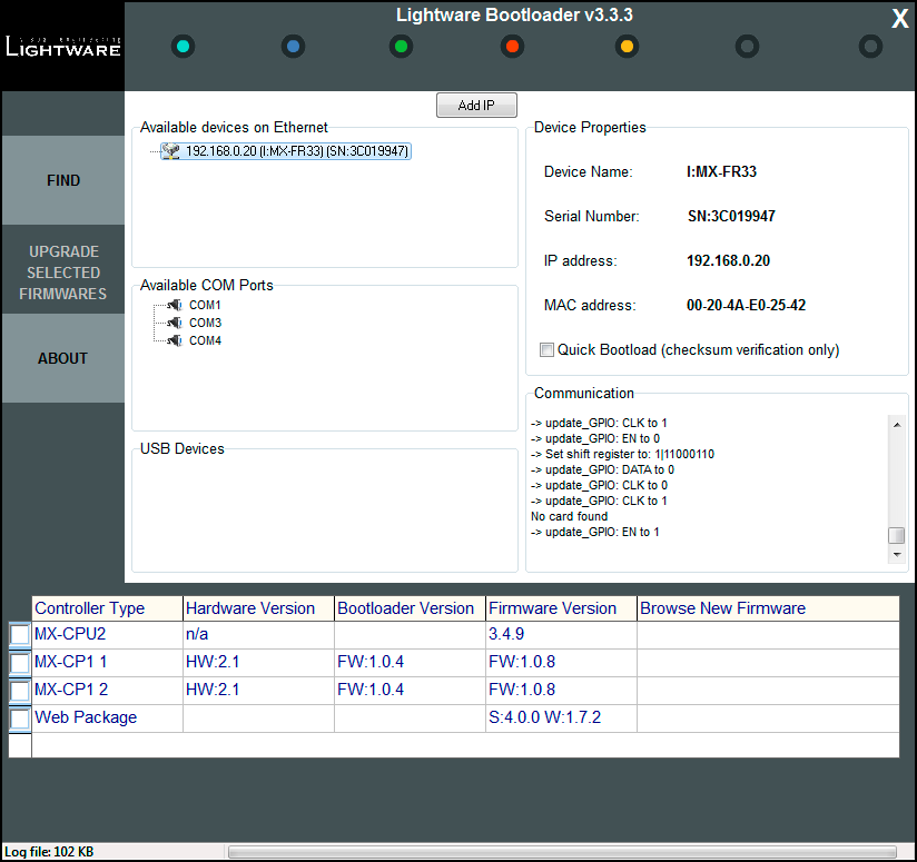
MX-CPU2 is the main processor’s firmware. MX-CP controllers are the front panel button modules. The number of the MX-CP modules depends on the matrix frame size. These modules must have the same firmware installed. The Web Package is the module that handles the LAN connections and hosts the built-in website.
Step 8.Browse the new firmware(s).
Click the corresponding cell in the Browse New Firmware column. A dialog pops up, to confirm if you really want to modify the path. Now you can browse the new firmware file to upload. After opening the new file, the new firmware field will contain the name of the firmware file.

Step 9.Update firmware(s)
Click Upgrade selected firmwares button. A confirmation message appears. After clicking on the Yes button the selected controllers are being reprogrammed with the firmware you selected. If you select a file that does not fit the selected controller, you will get an information message about which file is wrong. If you selected a controller to update, but you had not selected a file for it, then you will also get an information message about which file is missing.
Quick Bootload mode can be switched on or off at any time. No data verification is done after writing if the checksum was correct, which makes the bootloader faster.
ATTENTION!The reprogramming may take 3-8 minutes per controller.
A progress bar will show the current state of the reprogramming on the bottom of the window. In the case of certain boards the erasing process is run before the programming, so the progress bar runs up twice.

When the reprogramming is finished, a Done! message will appear in the bottom left corner. The application closes the connection, and the router restarts.
Step 10.Done!

If the update was successful, a window pops up. Now you can close the application, or you can select another matrix router to update. After closing the bootloader application, switch the updated devices off and then on. Now the router is ready to be used with the new firmware!
8.2. Forced Firmware Update
If a previous update process has failed or the matrix is not listed in the available devices list, then the normal firmware updating process may not work. In this case the procedures below can help.
Device Not Listed
The IP address of a matrix may not be listed in the list because of wrong network configuration or if a previous update process failed. In this case the router’s IP address can be added manually to the list with the Add IP button.
ATTENTION!Use this option with caution, as the manually typed IP address is not checked if it is a Lightware device or not. If the address belongs to an unknown network device, then this may cause the malfunction of the device.
Step 1.Type the IP address of the matrix router (check on the front panel LCD if possible).
Step 2.The TCP port can be selected manually if the checkbox is selected. If the port is not set, then the default port 10001 is used.
Step 3.Click on the Add button. The IP address will appear in the list.

Cannot Connect to Device
If the IP address was added manually, then the bootloader software usually cannot detect the device type and cannot connect to it automatically. The IP addresses with unrecognized devices appear in the list without showing the type and serial number.
ATTENTION!Use this option with caution, as the manually typed IP address is not checked if it is a Lightware device or not. If the address belongs to an unknown network device, then this may cause the malfunction of the device.
Step 1.Add the IP address manually as described above.

Step 2.Right click on the desired IP address and select Handle as MX-CPU2.
Step 3.The software tries to connect to the device handling it as the selected type. If the connection is successful, then the further process is the same as the normal firmware update.
8.3. Firmware Update of TPS(2) Ports
All MX-TPS and TPS2 I/O boards’ port has a separate firmware. All of the 8 firmwares can be different version, and they are stored on the board instead of the MX-CPU2. Therefore the firmware update must be performed differently than with the MX-CPU2. The firmware update can be performed with the Lightware Device Controller software.
INFO:All settings of the matrix remain after TPS firmware update.
Updating Steps in a Nutshell
Step 1.Download and save all the firmware files that you want to update.
Step 2.Connect the Lightware device and the computer via LAN port.
Step 3.Start the Lightware Device Controller application.
Step 4.Establish the connection with the device.
Step 5.Open the input or output parameters window.
Step 6.Click on the Firmware update button.
Step 7.Upload the firmware files to the SD card.
Step 8.Select the desired ports.
Step 9.Starting the update process.
Step 10.Restart the device.
Detailed Instructions
The TPS(2) boards can be updated with the LDC software.
WARNING!Performing the update process via the LAN connection is strongly recommended.
Step 1.Download and save all the firmware files that you want to update. If you have a zipped archive, extract it.
Step 2.Make sure the LDC software is installed on your computer.
Step 3.Start the LDC and establish the connection with the matrix.
Step 4.Open the TPS firmware update window.
By clicking on any TPS input or output label, a dialog window appears showing the parameters for the corresponding input or output port. The current firmware version can be seen in the Firmware settings section.

Step 5.Click the Update Firmware button; a new dialog window appears showing the uploaded firmwares and the available TPS ports. If the frame contains TPS input and output bboards, the user can reach both from this window.
Use the radio button to change between inputs and outputs.

Step 6.Upload the firmware files to the SD card. Click on the Upload new firmware from file to SD card button and browse the file. Find the firmware file, then click on Open. A progress bar shows the current state of the process.
WARNING!Do not close the software or disconnect the device before the upload is finished!
ATTENTION!Only one firmware file can be uploaded at the same time. Repeat Step 6 for uploading another file.
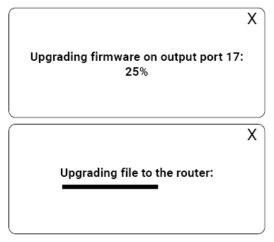
Step 7.Select the desired ports to update. Use the tick circles to select/deselect the ports.
Step 8.Start the update process. Click on the Upgrade selected ports. It takes about 12 minutes if all the ports are updated on a board.
WARNING!Do not turn off or disconnect your device before the update is finished.
Step 9.Finish and restart. If the process is finished, the process indicator is changed to Firmware update finished for a second. Close the LDC and restart the matrix.
Usually, if the system seems not to transport the signal as expected, the best strategy for troubleshooting is to check signal integrity through the whole signal chain starting from source side and moving forward to receiver end.

|
Link to connections/cabling section. |

|
Link to front panel operation section. |

|
Link to LDC software section. |

|
Link to LW2 protocol commands section. |

|
Link to LW3 protocol commands section. |
The following sections are available in the chapter:
9.1. Use Cases
|
Symptom |
Root cause |
Action |
Refer to |
|
|
General Problems |
||||
|
CPU Link LED does not blink |
The matrix is not powered correctly |
Reset the matrix by an LW2 command, or unplug and reconnect the power cable. |

|
|

|
||||
|
General Video Signal Problems |
||||
|
Picture is not displayed or distorted |
Video connectors are loose |
Make sure the connectors fit well. |

|
|
|
Different port is selected in the source/display device |
Select the desired/connected port. |
|||
|
Analog signal is connected to a digital port |
Even though I/O boards are equipped with DVI-I ports, only the indicated ports accept analog signals. |

|
||
|
The desired input and output ports are not connected |
Check the crosspoint state in the matrix. |

|
||
|
The desired output is muted |
Unmute the port. |

|
||
|
The sink device is not able to display the image |
Emaulate another EDID (e.g. Lightware's Universal EDID). |

|
||
|
TCP/IP Connection Problems |
||||
|
Cannot connect to the matrix or send a command via LAN |
Not the proper cable is applied |
For direct connection, use a cross-link cable; for connecting the matrix to a hub or switch, use a straight patch cable. |

|
|
|
Connected to a different network (e.g. Wi-Fi vs. LAN) |
Check the settings of your computer and make sure it is connected to the same network as the matrix. |
|||
|
Improper IP address is applied in the matrix |
Set the IP address manually for a direct connection. |

|
||
|
IP address conflict in the network |
Check the current IP address; set a dynamic IP address if DHCP server is in the network. |

|
||
|
Incorrect port address is set |
The matrix accepts LAN connection on the 10001 TCP port. |
|
||
|
The port is blocked by a firewall in the network |
Check the firewall settings. |
|||
|
Not the right protocol is selected |
Check the current protocol setting and set the desired option. |
|
||
|
Serial Connection Problems |
||||
|
Cannot connect to the matrix or send a command via the RS-232 port |
Not the right protocol is selected |
Check the current protocol setting and set the desired option. |
|
|
|
Not the right cable is plugged in |
Check the connection: a straight-through male-female serial cable is needed. |
|
||
|
Serial port settings do not meet |
Set the same parameters in the matrix and in the connected serial device. |
|
||
|
TP/TPS port problems |
||||
|
Picture is not displayed or distorted |
The CATx cable is connected to an Ethernet interface |
Check the cable connections. |
|
|
|
Low quality CATx cables applied |
Due to high data rates, high quality cabled are recommended, CAT6 or CAT7 S/FTP cables. |
|||
|
The crimping of the CATx cables is not right |
Check the wire colors of the connectors to meet the requirements. |
|
||
9.2. How to Speed Up the Troubleshooting Process

Lightware’s technical support team is always working hard to provide the fastest support possible. Our team’s response time is one of the best in the industry, and in the toughest of cases we can directly consult with the hardware or software engineer who designed the product to get the information from the most reliable source.
However, the troubleshooting process can be even faster… with your help.
There are certain pieces of information that push us in the right direction to find the root cause of the problem. If we receive most of this information in the first e-mail, or it is gathered at the time when you call us, then there is a pretty high chance that we will be able to respond with the final solution right away.
This information is the following:
▪Schematic (a pdf version is preferred, but a hand drawing is sufficient).
▪Serial number(s) of the device(s) (it is either printed somewhere on the box or you can query it in the Device Controller software or on the built-in website).
▪Firmware versions of the devices (please note that there may be multiple CPUs or controllers in the device and we need to know all of their firmware versions, a screenshot is the best option).
▪Cable lengths and types (in our experience, it’s usually the cable).
▪Patch panels, gender changers or anything else in the signal path that can affect the transmission.
▪Signal type (resolution, refresh rate, color space, deep color).
▪Emulated EDID(s) (please save them as a file and send it to us).
▪Actions to take in order to re-create the problem (if we cannot reproduce the problem, it is hard for us to find the cause).
▪Photo or video about the problem (‘image noise’ can mean many different things, it’s better if we see it too).
▪Error logs from the Device Controller software.
▪In the case of an Event Manager issue, the event file and/or backup file from the Device Controller software.
The more of the information above you can give us, the better. Please send this information to the Lightware Support Team (support@lightware.com) to speed up the troubleshooting process.
The following sections contain descriptions and useful technical information on how the devices work in the background. The content is based on experiences and cases we met in practice. These sections help to understand features and technical standards like the following:
10.1. EDID Management
10.1.1. Understanding the EDID
The Extended Display Identification Data (EDID) is the passport of display devices (monitors, TV sets, projectors). It contains information about the capabilities of the display, such as supported resolutions, refresh rates (these are called Detailed Timings), the type and manufacturer of the display device, etc.
After connecting a source to a display (DVI, HDMI, DP), the source reads out the EDID to determine the resolution and refresh rate of the image to be transmitted.

EDID Communication
Most DVI computer displays have 128-byte long EDID structure. However, Digital Televisions and HDMI capable displays may have another 128 bytes, which is called E-EDID and defined by CEA (Consumer Electronics Association). This extension contains information about additional Detailed Timings, audio capabilities, speaker allocation and HDMI capabilities. It is important to know that all HDMI capable devices must have CEA extension, but not all devices with CEA extension are HDMI capable.
Common Problems Related to EDID
Problem: “My system consists of the following: a computer, a Lightware device, a WUXGA (1920x1200) LCD monitor, and an SXGA (1280x1024) projector. I would like to see the same image on the monitor and the projector. What EDID should I choose on the Lightware device?”
Solution: If you want to see the image on both displays, you need to select the resolution of the smaller display (in this case SXGA), otherwise the smaller display may not show the higher resolution image.
Problem: “I have changed to a different EDID on an input port of the Lightware device to have a different resolution but nothing happens.”
Solution: Some graphics cards and video sources read out the EDID only after power-up and later they do not sense that EDID has been changed. You need to restart your source to make it read out the EDID again.
10.1.2. Advanced EDID Management
Each DVI sink (e.g. monitors, projectors, plasma displays, etc...) must support the EDID data structure. Source BIOS and operating systems are likely to query the sink using DDC2B protocol to determine what pixel formats and interface are supported. DVI standard uses EDID data structure to identify the monitor type and capabilities. Most DVI sources (VGA cards, set top boxes, etc.) will output DVI signal after accepting the connected sink’s EDID information. In the case of EDID readout failure or missing EDID, the source will not output DVI video signal.
Lightware devices provide the Advanced EDID Management function that helps system integration. The built-in EDID Router can store and emulate factory pre-programmed- and User programmable EDIDs. The EDID of the attached monitors or projectors for each output are stored in a non-volatile memory. This way the EDID of a monitor is available when the monitor is unplugged or switched off.
Any EDID can be emulated on any input. An emulated EDID can be copied from the EDID router’s memory (static EDID emulation), or from the last attached monitor’s memory (dynamic EDID emulation). For example, the Lightware device can be set up to emulate a sink device, which is connected to one of the outputs. In this case, the EDID automatically changes, if the monitor is replaced with another display device (as long as it has a valid EDID).
EDID is independently programmable for all inputs without affecting each other. All inputs have their own EDID circuit.
INFO:The user is not required to disconnect the video cable to change an EDID as opposed to other manufacturer’s products. EDID can be changed even if a source is connected to the input and powered ON.
INFO:When EDID has been changed, the router toggles the HOTPLUG signal for 2 seconds. Some sources do not sense this signal. In such cases, the source device must be restarted or powered OFF and ON again.
Lightware Visual Engineering is a legal HDCP adopter. Several functions have been developed which helps to solve HDCP related problems. Complex AV systems often have both HDCP and non-HDCP components. The matrix allows transmitting HDCP encrypted and unencrypted signals. The devices will be still HDCP compliant as they will never output an encrypted signal to a non-HDCP compliant display device. If an encrypted signal is switched to a non-compliant output, a red screen alert or muted screen will appear.
10.2.1. Protected and Unprotected Content
Many video sources send HDCP protected signal if they detect that the sink is HDCP capable – even if the content is not copyrighted. This can cause trouble if an HDCP capable device is connected between the source and the display. In this case, the content cannot be viewed on non-HDCP capable displays and interfaces like event controllers. Rental and staging technicians often complain about certain laptops, which are always sending HDCP encrypted signals if the receiver device (display, matrix router, etc.) reports HDCP compliancy. However, HDCP encryption is not required all the time e.g. computer desktop image, certain laptops still do that.
To avoid unnecessary HDCP encryption, Lightware introduced the HDCP enabling/disabling function: the HDCP capability can be disabled in the Lightware device. If HDCP is disabled, the connected source will detect that the sink is not HDCP capable, and turn off authentication.
10.2.2. Disable Unnecessary Encryption
HDCP Compliant Sink
All the devices are HDCP-compliant, no manual setting is required, both protected and unprotected contents are transmitted and displayed on the sink.

Not HDCP-compliant Sink 1.
Not-HDCP compliant sink is connected to the matrix. Some sources (e.g. computers) always send HDCP encrypted signals if the receiver device reports HDCP compliancy, however, HDCP encryption is not required all the time (e.g. computer desktop image). If HDCP is enabled in the matrix, the image will not be displayed on the sink.

Setting the HDCP parameter to Auto on the output port and disable HDCP on the input port, the transmitted signal will not be encrypted if the content is not protected. Thus, non-HDCP compliant sinks will display non-encrypted signal.
Not HDCP-compliant Sink 2.
The layout is the same as in the previous case: non-HDCP compliant display device is connected to the matrix but the source would send protected content with encryption. If HDCP is enabled on the input port of the matrix, the source will send encrypted signal.

The sink is not HDCP compliant, thus, it will not display the video signal (but blank/red/muted/etc. screen). If HDCP is disabled on the input port of the matrix, the source will not send the signal. The solution is to replace the display device to an HDCP-capable one.
10.3. Pixel Accurate Reclocking
Signal reclocking is an essential important procedure in digital signal transmission. After passing the reclocking circuit, the signal becomes stable, jitter-free, and can be transmitted over more equipment like processors, or event controllers. Without reclocking, sparkles, noise, and jaggies appear on the image.
Lightware’s sophisticated Pixel Accurate Reclocking technology fixes more problems than general TMDS reclocking. It removes not only intra-pair skew but inter-pair skew as well. The Pixel Accurate Reclocking circuit eliminates the following errors:
Intra-pair skew
Skew between the + and - wires within a differential wire pair (e.g. Data2- and Data2+). It’s caused by different wire lengths or slightly different wire construction (impedance mismatch) in DVI cable. It results in jitter.

Inter-pair skew
Skew between two differential wire pairs in a cable. It is caused by different wire pair lengths or different number of twists in the DVI cable. Too much inter-pair skew results color shift in the picture or sync loss.

Jitter
Signal instability in the time domain. The time difference between two signal transitions should be a fixed value, but noise and other effects cause variations.

Noise
Electromagnetic interference between other electronic devices such as mobile phones, motors, etc. and the DVI cable are coupled onto the signal. Too much noise results in increased jitter.

10.4. Dual-Link DVI signal
The Dual-Link DVI interface can operate in either Single-Link or Dual-Link mode. The chosen mode depends on the pixel clock frequency of the signal and it is selected by the hardware automatically. For pixel clock frequencies lower than 165 MHz, Single-Link mode is selected. For higher pixel clock frequencies (up to 330 MHz), Dual-Link mode is selected. It is important to know that pixel clock frequency is not the same as TMDS clock frequency when it comes to Dual-Link DVI.
The pixel clock frequency in Single-Link transmission is a 10th part of the data rate. The maximum data rate of the Single-Link transmission is 1.65 Gbps per TMDS channel and the maximum pixel clock frequency is 165 MHz. In this case the pixel clock frequency equals the TMDS clock frequency. The pixel clock frequency in Dual-Link transmission (when in Dual-Link mode) is a 5th part of the data rate. The maximum data rate of Dual-Link transmission is still 1.65 Gbps per TMDS channel but the maximum pixel clock frequency is 330 MHz. In this case the pixel clock frequency is two times the TMDS clock frequency.
The DVI standard maximizes the data rate of the TMDS channels in 1.65 Gbps. Dual-Link DVI interface enables a higher resolution compared to the Single-Link transmission by doubling the number of wire pairs to transmit the video signal. In Single-Link cables 3 wire pairs carry the color information (red, green and blue) and one wire pair carries the clock signal (TMDS clock).

Video lines of the Single-Link interface
In Dual-Link cables, 6 wire pairs carry the color information next to the TMDS clock signal. One color component is carried by two wire pairs, where one wire pair carries the odd pixels and the other wire pair carries the even pixels.

Video lines of the Dual-Link interface
INFO:The colors of the wire pairs in the picture represent the color information they carry and not the color of the actual wires inside the cable.
10.5. RS-232 Command Transmission
Lightware Hybrid Modular Matrix system provides bidirectional RS-232 signal transmission at remote endpoints. The feature is implemented on certain boards like .... transmitters and receivers. The desired third-party device can send and receive commands directly to/from the far endpoints. No additional cable is required as the commands are sent through the cable (fiber, TPS) that is connected to the I/O board in the matrix.
Lightware Hybrid Modular Matrix system provides easy interfacing of RS-232 control commands for devices at remote endpoints through bidirectional RS-232 ports on the matrix I/O boards (MX-HDMI-OPT-IB, MX-HDMI-OPT-OB, and MX-TPS-IB, MX-TPS-OB), transmitters and receivers. The desired application (e.g. control system, touch screen) sends and receives short RS-232 control commands directly from the far endpoints. The commands are sent out directly from the far endpoints independently on each optical or TPS port over the same fiber or CATx cable, used by the video/audio transmission so that no additional cable is required for system control.
Home Cinema Application
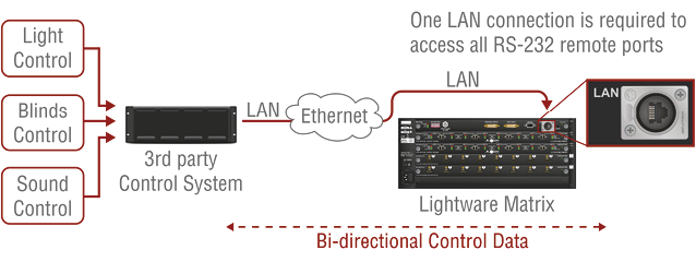
The RS-232 control command is transmitted from the touch control to the projector through the matrix and the receiver on a single fiber, which also transmits the video and audio. The touch screen can control the matrix as well to perform crosspoint-switching or change settings in the frame.
Conference Room Application

Both professional sources and displays can be controlled through the AV network. The touch screen control sends a “presentation starting” command to the control system, which adjusts the lighting and shutters, turns on the projector and switches the crosspoint’s output to the lectern laptop.
Control System Connection

The third-party control system is connected to the Lightware crosspoint via a LAN connection to access all RS-232 remote ports. Control commands can only be sent to and received from the matrix on the LAN connection by the control system.
The baud rate can be 9600, 19200, 36800, 57600. There is a stop bit and no parity bit, covering all consumer devices on the market to be suitable for the communication. The control protocol has two different methods for sending and receiving RS-232 data to or from the frame: ASCII mode could be used only with human readable characters, while binary mode can handle any data.
A maximum of 54 bytes of data can be sent / received at once, e.g. it is not possible to transfer files or to do a firmware update via the router. It is also important that the control interfaces on the router (USB, IP, and RS-232) use a shared resource. Please ensure that across all connections no more than 8 unanswered queries are in progress. If proper locking can not be implemented, waiting for 600 ms between each query on each connections is generally sufficient.
10.6. The RICOD Technology
10.6.1. Introduction
The main goal of Remote Input Control Over DDC (RICOD) is to control the remote Lightware transmitters attached to a router (local device). The control means input switching (select video and audio sources) and locking / unlocking the remote buttons / switches.
ATTENTION!There is no possibility to send other kind of commands, including Lightware protocol commands or any other character sequence. The "RS-232 extension" function is out of the question.
ATTENTION!RICOD is Lightware’s intellectual property and proprietary function. It works only with Lightware devices.
10.6.2. Operation
Master and Slave Modes
First of all, it is important to understand the direction of RICOD and the working modes. Lightware's RICOD-capable devices are able to send out remote switching commands on their video inputs towards another RICOD capable device’s video output and / or they can receive remote switching commands on their video outputs from another RICOD capable device’s video input. One device can work as a Master or a Slave:
Master
If a device sends out RICOD commands over its video input, it works as a Master, like the device on the right side. Lightware matrix routers (e.g. MX-FR frames with CPU2) work as RICOD Masters typically.

Slave
If a device receives RICOD commands over its video outputs, it works as a Slave, like the device on the left side. In this case, the devices are capable of receiving commands over their outputs (e.g. connected to another Lightware device) if the function is enabled.
This means that the remote device is capable of being controlled from that given output. (The command affects only the output where the RICOD command was received). The Lightware transmitters (e.g. WP-UMX-TP-TX100) work as RICOD Slaves typically.

Factory Defaults
After a firmware update the Slave mode is always enabled (commands from the Master devices are accepted and executed) and the Master mode is always disabled. That state is realoded when factory default settings are restored by protocol command (FACTORY=ALL). For more information about reloading the factory defaults, see the user’s manual of the devices.
10.6.3. Enable / Disable RICOD
Users can enable or disable the RICOD function for each input and output video port separately. For example, one can enable the RICOD on the 1st and the 2nd video input and the 1st and the 3rd video output ports. RICOD is disabled on the other video input and output ports; the figure below shows this case. Video ports where RICOD is enabled are green.

The RICOD can be enabled or disabled by LW2 protocol commands for every Lightware device. (For more information, see the RICOD Related Commands section.)
10.6.4. Validity of RICOD
The last command will be saved for each input and will be preserved until a new command arrives or until the function is disabled. If the remote controlled device is restarted, replaced or disconnected and connected again, then the command will be executed again. The command will take effect even if the local device (e.g. the MX-FR matrix with CPU2) is restarted or the function is enabled again.

INFO:The communication between the devices is uni-directional, so there is no feedback from the remote controlled device.
10.6.5. Locking the Remote Device
The intention of this feature is to prevent accidental or unwanted switching when the remote device is installed near the end-users. The remote device can be locked by the local device via a RICOD command. The behavior is different for the video routers and for the extenders:
Extenders
If an extender (e.g. WP-UMX-TP-TX100) receives a lock command by the RICOD function, it will disable the front panel switching buttons. The buttons are disabled until the device is disconnected (connection is detected by the Hotplug detect signal that is carried by the DDC CAT cable when using CATx extenders) or the remote lock command is cleared by the local device. This can be done by turning off the RICOD function or by turning off only the lock command.
If a new device is connected that does not support RICOD commands, then the remote lock will be disabled.
Note that when the buttons are disabled, they do not react at all - switching and unlocking are also impossible.
The transmitters are still able to receive and execute commands via their local control interface (e.g. RS232 or USB) while RICOD lock is enabled. The remote lock command affects only the buttons, but does not prevent the switching if it is commanded locally.
Locking Operation Flowchart
Buttons on the extenders can be locked by front panel operation or remotely, but the two ways of locking are not the same. If buttons were locked by a front panel operation, they can be unlocked by a RICOD unlock command followed by an unlock operation on the front panel.

Video Routers
The routers behave differently, because locking the whole front panel is not reasonable. When the RICOD function is enabled for an output port (see RICOD_SLEN command in the Querying the RICOD SLAVE Status section) and a lock command is received over the same port, then the output port will be "output locked". This is the same output lock function as described in the Output Lock section. The output lock is reported back by the protocol (shown in the controller software and on the web, as well) and displayed on the front panel. The output lock can be overridden and turned off by protocol or front panel.
If the output lock is enabled for a given port, a remote RICOD command is also able to turn it off.
ATTENTION!The accepted RICOD command overrides the output lock function. If the RICOD function is turned on for a given output port, then the output lock condition can be changed remotely.
10.6.6. RICOD-Capable Devices
The RICOD functionality is currently implemented in the following devices:
▪MX-FR frames with CPU2, firmware version 3.3.5r and above.
▪UMX4x4 Pro, firmware version 1.2.4r and above.
▪UMX-TP-TX100R, firmware version 1.1.6r and above.
▪WP-UMX-TP-TX100, firmware version 1.1.0r and above.
▪FP-UMX-TP-TX100, firmware version 1.1.0r and above.
* The MX-FR series modular matrix frames with MX-CPU2 processor boards (with firmware version 3.3.5r and above) support reduced RICOD capabilities: only MASTER mode is available and only by protocol commands. RICOD SLAVE mode and the front panel operation are not implemented.
Tables, drawings, guides, technical details and the hashtag keyword list as follows:
11.1. Specifications
INFO:Specificatios are subject to change without notice.
11.1.1. General
|
Compliance |
CE, UKCA |
|
EMC (emission) |
EN 55032:2015+A1:2020 |
|
EMC (immunity) |
EN 55035:2017+A11:2020 |
|
RoHS |
EN 63000:2018 |
|
Electrical safety |
EN 60065:2002 + A1:2006 + A11:2008 + A2:2010 + A12:2011 |
|
Laser safety |
EN 60825-1:2014+A11:2021 |
|
Warranty |
3 years |
|
Operating temperature |
0° to +50°C (+32° to +122°F) |
|
Operating humidity |
10% to 90%, non-condensing |
|
Cooling |
by cooling fans |
11.1.2. Power
MX-FR9 and MX-FR17
|
Power supply option |
Built-in PSU |
|
Supported power source |
100-240 V AC; 50/60 Hz |
|
Power consumption (max) |
160 W |
|
Heat dissipation |
546 BTU/h |
|
AC power connector |
IEC C14 receptacle |
|
AC fuse |
F 3.15 A |
MX-FR9R and MX-FR17R
|
Power supply option |
Swappable PSU |
|
Supported power source |
100-240 V AC; 50/60 Hz |
|
Power supply unit(s) type |
MX-PSU-350 |
|
Power consumption (max) |
350 W |
|
Heat dissipation |
1194 BTU/h |
|
AC power connector |
IEC C14 receptacle |
MX-FR33L
|
Power supply option |
Built-in PSU |
|
Supported power source |
115-230 V AC; 50/60 Hz |
|
Power consumption (max) |
250 W |
|
Heat dissipation |
854 BTU/h |
|
AC power connector |
IEC C14 receptacle |
|
AC fuse |
F 6.3 A L |
MX-FR33R
|
Power supply option |
Swappable PSU |
|
Supported power source |
100-240 V AC; 50/60 Hz |
|
Power supply unit(s) type |
MX-PSU-350 |
|
Power consumption (max) |
320 W |
|
Heat dissipation |
1092 BTU/h |
|
AC power connector |
IEC C14 receptacle |
MX-FR65R and MX-FR80R
|
Power supply option |
Swappable PSU |
|
Supported power source |
100-240 V AC; 50/60 Hz |
|
Power supply unit(s) type |
FNP850-12RG |
|
Power consumption (max) |
2000 W |
|
Heat dissipation |
6830 BTU/h |
|
AC power connector |
IEC C14 receptacle |
11.1.3. Enclosure
MX-FR9 and MX-FR17
|
Rack mountable |
Yes, 4U high |
|
Enclosure material |
1 mm steel |
|
Dimensions in mm |
W482 x D300 x H176 |
|
Dimensions in inch |
W19.0 x D11.8 x H6.9 |
|
Weight (with MX-CPU2 board) |
10.8 kg (23.8 lbs) |
MX-FR9R and MX-FR17R
|
Rack mountable |
Yes, 4U high |
|
Enclosure material |
1 mm steel |
|
Dimensions in mm |
W482 x D300 x H176 |
|
Dimensions in inch |
W19.0 x D11.8 x H6.9 |
|
Weight (with MX-CPU2 board) |
11.7 kg (25.8 lbs) |
MX-FR33L
|
Rack mountable |
Yes, 6U high |
|
Enclosure material |
1 mm steel |
|
Dimensions in mm |
W482 x D300 x H265 |
|
Dimensions in inch |
W19.0 x D15.7 x H10.4 |
|
Weight (with MX-CPU2 board) |
11.6 kg (25.6 lbs) |
MX-FR33R
|
Rack mount |
Yes, 7U high |
|
Enclosure material |
1 mm steel |
|
Dimensions in mm |
W482 x D400 x H309 |
|
Dimensions in inch |
W19.0 x D15.7 x H12.1 |
|
Weight of the frame (with MX-CPU2 board) |
33.9 kg (74.7 lbs) |
|
Weight of the MX-PSU-350 |
1 kg (2.2 lbs) |
MX-FR65R and MX-FR80R
|
Rack mountable |
Yes, 15U high |
|
Enclosure material |
1 mm steel |
|
Dimensions in mm |
W482 x D393 x H665 |
|
Dimensions in inch |
W19.0 x D15.5 x H26.2 |
|
Weight of the frame (with MX-CPU2 board) |
27.6 kg (60.8 lbs) |
|
Weight of the MX-PSU-850 |
1.4 kg (3.1 lbs) |
11.1.4. I/O Ports of the MX-CPU2 Board
Inputs
|
Connectors |
29-pole DVI-I digital only |
|
Input cable equalization |
No |
|
EDID emulation |
Yes |
|
Reclocking |
Pixel Accurate Reclocking |
Outputs
|
Connectors |
29 pole DVI-I digital only |
|
Output pre-emphasis |
No |
|
Reclocking |
Pixel Accurate Reclocking |
|
EDID read |
Yes |
|
+5V output current |
500 mA continuous each (protected) |
11.1.5. Video Inputs - I/O Boards
INFO:AV input interface depends on the type of the I/O board.
HDMI Input
|
Connector type |
19-pole HDMI Type A receptacle |
|
AV standard |
DVI 1.0, HDMI 1.4 |
|
HDCP compliance |
HDCP 1.4 |
|
Color space |
RGB, YCbCr |
|
Video delay |
0 frame |
|
Supported resolutions at 8 bits/color * |
up to 4096x2048@30Hz (4:4:4) or 4096x2048@60Hz (4:2:0); up to 3840x2160@30Hz (4:4:4) or 3840x2160@60Hz (4:2:0); 1920x1080@60Hz (4:4:4) up to 12 bits/color |
|
Reclocking |
Pixel Accurate Reclocking |
|
3D support |
Yes |
|
Audio formats |
8 channel PCM |
|
Dolby TrueHD, DTS-HD Master Audio 7.1 |
|
|
Input cable equalization |
Yes, +12dB fixed |
* All standard VESA, CEA and other custom resolutions up to 300MHz (HDMI1.4) are supported.
DVI Input (with digital signal support)
|
Connector type |
29-pole DVI-I |
|
AV standard |
DVI 1.0, HDMI 1.4 |
|
HDCP compliance |
HDCP 1.4 |
|
Color space |
RGB, YCbCr |
|
Video delay |
0 frame |
|
Supported resolutions at 8 bits/color * |
up to 4096x2048@30Hz (4:4:4) or 4096x2048@60Hz (4:2:0); up to 3840x2160@30Hz (4:4:4) or 3840x2160@60Hz (4:2:0); 1920x1080@60Hz (4:4:4) up to 12 bits/color |
|
Reclocking |
Pixel Accurate Reclocking |
|
3D support |
Yes |
|
Audio formats |
8 channel PCM; Dolby TrueHD, DTS-HD Master Audio 7.1 |
|
Input cable equalization |
Yes, +12dB fixed |
* All standard VESA, CEA and other custom resolutions up to 300MHz (HDMI1.4) are supported.
DVI-DL Input (with digital signal support)
|
Connector type |
29-pole DVI-I |
|
AV standard |
DVI 1.0 |
|
Color space |
RGB |
|
Video delay |
0 frame |
|
Supported resolutions at 8 bits/color |
up to 2560x1600@60Hz (4:4:4); 1920x1200@120Hz, 24 bit |
|
3D support |
Yes |
|
Audio formats |
8 channel PCM |
|
Input cable equalization |
Yes, +12dB fixed |
DVI Input (with analog signal support)
|
Connector type |
29-pole DVI-I |
|
AV standard |
DVI 1.0 |
|
Color depth |
up to 24 bits, 8 bits/color |
|
Color space |
Analog RGB and YPbPr video |
|
Max. video resolutions |
1600x1200@60 Hz, 24 bits |
3GSDI Input
|
Connector type |
BNC |
|
AV standard |
3G-SDI |
|
Color depth |
10 bit / Y, 10 bit / CbCr, 12 bit RGB |
|
Color space |
20 bit |
|
Supported video formats |
SD-SDI, HD-SDI, 3G-SDI |
|
3D support |
No |
|
EDID emulation |
No |
|
Audio capability |
8 channel PCM |
TPS Input
|
Connector type |
RJ45 connector |
|
Power over Ethernet (PoE) |
yes * (IEEE 802.3af) |
|
Compliance |
HDBaseTTM |
|
HDCP compliance |
HDCP 1.4 |
|
Transferred signals |
Video, Audio, RS-232, Infrared, Ethernet |
|
Color space |
RGB, YCbCr |
|
Video delay |
0 frame |
|
Supported resolutions at 8 bits/color ** |
up to 4096x2048@30Hz (4:4:4) or 4096x2048@60Hz (4:2:0); up to 3840x2160@30Hz (4:4:4) or 3840x2160@60Hz (4:2:0); 1920x1080@60Hz (4:4:4) up to 12 bits/color |
|
Audio formats |
8 channel PCM; Dolby TrueHD, DTS-HD Master Audio 7.1 |
* PoE function is available for the MX-TPS-IB-P series input boards only.
11.1.6. Video Outputs - I/O Boards
INFO:AV output interface depends on the type of the I/O board.
HDMI Output
|
Connector type |
19-pole HDMI Type A receptacle |
|
AV standard |
DVI 1.0, HDMI 1.4 |
|
HDCP compliance |
HDCP 1.4 |
|
Color space |
RGB, YCbCr |
|
Video delay |
0 frame |
|
Supported resolutions at 8 bits/color ** |
up to 4096x2048@30Hz (4:4:4) or 4096x2048@60Hz (4:2:0); up to 3840x2160@30Hz (4:4:4) or 3840x2160@60Hz (4:2:0); 1920x1080@60Hz (4:4:4) up to 12 bits/color |
|
Audio formats |
8 channel PCM |
|
Dolby TrueHD, DTS-HD Master Audio 7.1 |
|
|
Input cable equalization |
Yes, +12dB fixed |
** All standard VESA, CEA and other custom resolutions up to 300MHz (HDMI1.4) are supported.
DVI Output (with digital signal support)
|
Connector type |
29-pole DVI-I |
|
AV standard |
DVI 1.0, HDMI 1.4 |
|
HDCP compliance |
HDCP 1.4 |
|
Color space |
RGB, YCbCr |
|
Video delay |
0 frame |
|
Supported resolutions at 8 bits/color * |
up to 4096x2048@30Hz (4:4:4) or 4096x2048@60Hz (4:2:0); up to 3840x2160@30Hz (4:4:4) or 3840x2160@60Hz (4:2:0); 1920x1080@60Hz (4:4:4) up to 12 bits/color |
|
Reclocking |
Pixel Accurate Reclocking |
|
3D support |
Yes |
|
Audio formats |
8 channel PCM; Dolby TrueHD, DTS-HD Master Audio 7.1 |
|
Output preemphasis |
Yes, +6dB fixed |
* All standard VESA, CEA and other custom resolutions up to 300MHz (HDMI1.4) are supported.
DVI-DL Output (with digital signal support)
|
Connector type |
29-pole DVI-I |
|
AV standard |
DVI 1.0 |
|
Color space |
RGB |
|
Video delay |
0 frame |
|
Supported resolutions at 8 bits/color |
up to 2560x1600@60Hz (4:4:4); 1920x1200@120Hz, 24 bit |
|
3D support |
Yes |
|
Audio formats |
8 channel PCM |
TPS Output
|
Connector type |
RJ45 connector |
|
Power over Ethernet (PoE) |
yes (IEEE 802.3af) * |
|
Compliance |
HDBaseTTM |
|
HDCP compliance |
HDCP 1.4 |
|
Transferred signals |
Video, Audio, RS-232, Infrared, Ethernet |
|
Color space |
RGB, YCbCr |
|
Video delay |
0 frame |
|
Supported resolutions at 8 bits/color ** |
up to 4096x2048@30Hz (4:4:4) or 4096x2048@60Hz (4:2:0); up to 3840x2160@30Hz (4:4:4) or 3840x2160@60Hz (4:2:0); 1920x1080@60Hz (4:4:4) up to 12 bits/color |
|
Audio formats |
8 channel PCM; Dolby TrueHD, DTS-HD Master Audio 7.1 |
* PoE function is available for the MX-TPS-OB-P series input boards only.
** All standard VESA, CEA and other custom resolutions up to 300MHz (HDMI1.4) are supported.
11.1.7. Fiber Optical Ports
ST Connector
|
Connector type |
ST receptacle |
|
Fiber type |
50/125 ST Multimode fiber |
|
Laser wavelengths |
850, 1310, 1550 nm |
|
Laser class specification |
Class 3R |
|
Transmitter output OMA * |
-6.25 dBm (worst case) |
|
Receiver OMA * sensitivity |
-14.25 dBm (worst case) |
|
Optical loss budget |
8 dBm (worst case) |
SC Connector
|
Connector type |
SC receptacle |
|
Fiber type |
50/125 ST Multimode fiber |
|
Laser wavelengths |
850, 1310, 1550 nm |
|
Laser class specification |
Class 3R |
|
Transmitter output OMA * |
-6.25 dBm (worst case) |
|
Receiver OMA * sensitivity |
-14.25 dBm (worst case) |
|
Optical loss budget |
8 dBm (worst case) |
* OMA: Optical Modulation Amplitude
LC Duplex Connector
|
Connector type |
LC duplex receptacle |
|
Fiber type |
50/125 ST Multimode fiber |
|
Laser wavelengths |
850, 1310, 1550 nm |
|
Laser class specification |
Class 3R |
|
Transmitter output OMA * |
-6.25 dBm (worst case) |
|
Receiver OMA * sensitivity |
-14.25 dBm (worst case) |
|
Optical loss budget |
8 dBm (worst case) |
Neutrik LC Duplex Connector
|
Connector type |
Neutrik NO2-4FDW type LC duplex |
|
Fiber type |
50/125 ST Multimode fiber |
|
Laser wavelengths |
850, 1310, 1550 nm |
|
Laser class specification |
Class 3R |
|
Transmitter output OMA * |
-6.25 dBm (worst case) |
|
Receiver OMA * sensitivity |
-14.25 dBm (worst case) |
|
Optical loss budget |
8 dBm (worst case) |
* OMA: Optical Modulation Amplitude
11.1.8. Audio Ports
Analog Audio Input
|
Connector type |
5-pole Phoenix connector |
|
Audio formats |
2-channel PCM |
|
Sampling frequency |
48 kHz |
|
Maximum input level |
+0 dBu, 0.77 Vrms, 2.19 Vpp |
|
Signal transmission |
Balanced signal |
|
Balance |
0 - 100 (50 = center) |
|
Gain |
0 dB - 6 dB |
Analog Audio Output
|
Connector type |
5-pole Phoenix connector |
|
Audio formats |
2-channel PCM |
|
Sampling frequency |
48 kHz |
|
Signal transmission |
Balanced signal |
|
Volume |
-78 dB - 0 dB |
|
Balance |
0 - 100 (50 = center) |
|
Nominal Differential Output Level @ 0 dB Gain |
+4 dBu |
|
Nominal Differential Output Level @ 3 dB Gain |
+7 dBu |
S/PDIF Input
|
Connector type |
RCA |
|
Audio formats |
S/PDIF |
|
Supported sample rates |
16 to 48 kHz |
|
AES/EBU compatibility |
No |
|
Bit depths |
Up to 24 bits |
S/PDIF Output
|
Connector type |
RCA |
|
Audio formats |
S/PDIF |
|
Supported sample rates |
16 to 48 kHz |
|
AES/EBU compatibility |
No |
|
Bit depths |
Up to 24 bits |
11.1.9. Control Ports
RS-232 Serial Port
|
Connector type |
9-pole D-SUB female |
|
Baud rates |
Between 4800 and 57600 Baud |
|
Data bits |
8 |
|
Parity |
None / Odd / Even |
|
Stop bits |
1 / 1.5 / 2 |
|
Control protocol |
Lightware Protocol (#1) / Protocol #2 |
Ethernet Port
|
Connector type |
Neutrik etherCON / RJ45 female connector |
|
Ethernet data rate |
10/100Base-T, full duplex with autodetect |
|
Power over Ethernet (PoE) |
Not supported |
|
Ethernet protocol |
TCP/IP, HTTP, TFTP, Telnet |
Alarm Output
|
Connector type |
SMPTE 269M standard BNC |
11.2. Applied Ports (Network Settings)
The following ports are necessary to pass via a network switch/firewall for a proper working between the device and the softwares:
|
Purpose/function |
Affected software |
Protocol |
Port nr. |
|
Device Discovery |
LDC |
UDP |
224.0.0.251:5353 |
|
Remote IP |
LDC |
UDP |
230.76.87.82:37421 |
|
LW2 protocol |
- |
TCP |
10001 |
|
Secondary protocol |
- |
TCP |
23 |
|
HTTP port |
- |
TCP |
80 |
11.3. Factory Default Settings
|
Network Settings |
|
|
IP address |
192.168.254.254 |
|
Subnet mask |
255.255.0.0 |
|
Static gateway |
0.0.0.0 |
|
DHCP |
Disabled |
|
LW2 Port number |
10001 |
|
HTTP Port number |
80 |
|
Control protocol |
LW2 |
|
Video Port Settings |
|
|
Crosspoint state |
I1 input port on all output ports |
|
Input/Output ports |
Unmuted, Unlocked |
|
Emulated EDID (input ports) |
F49 – Universal HDMI EDID |
|
EDID memory |
Empty (User and Dynamic EDIDs) |
|
Crosspoint presets |
All outputs to I1 |
|
Preset names |
Preset1, Preset2,... |
|
Port names |
Input1, Input2...; Output1, Output2... |
|
RS-232 Settings |
|
|
Baud rate |
57600 |
|
Databits |
8 |
|
Parity |
No |
|
Stopbits |
1 |
|
Control protocol |
LW2 |
|
Mem. |
Resolution |
Type |
|||
|
F1 |
640 x |
480p |
@ 60.0 |
Hz |
D |
|
F2 |
848 x |
480p |
@ 60.0 |
Hz |
D |
|
F3 |
800 x |
600p |
@ 60.30 |
Hz |
D |
|
F4 |
1024 x |
768p |
@ 60.0 |
Hz |
D |
|
F5 |
1280 x |
768p |
@ 50.0 |
Hz |
D |
|
F6 |
1280 x |
768p |
@ 59.92 |
Hz |
D |
|
F7 |
1280 x |
768p |
@ 75.0 |
Hz |
D |
|
F8 |
1360 x |
768p |
@ 60.1 |
Hz |
D |
|
F9 |
1280 x |
1024p |
@ 50.0 |
Hz |
D |
|
F10 |
1280 x |
1024p |
@ 60.1 |
Hz |
D |
|
F11 |
1280 x |
1024p |
@ 75.1 |
Hz |
D |
|
F12 |
1400 x |
1050p |
@ 49.99 |
Hz |
D |
|
F13 |
1400 x |
1050p |
@ 59.99 |
Hz |
D |
|
F14 |
1400 x |
1050p |
@ 75.0 |
Hz |
D |
|
F15 |
1680 x |
1050p |
@ 59.99 |
Hz |
D |
|
F16 |
1920 x |
1080p |
@ 50.0 |
Hz |
D |
|
F17 |
1920 x |
1080p |
@ 60.0 |
Hz |
D |
|
F18 |
2048 x |
1080p |
@ 50.0 |
Hz |
D |
|
F19 |
2048 x |
1080p |
@ 59.99 |
Hz |
D |
|
F20 |
1600 x |
1200p |
@ 50.0 |
Hz |
D |
|
F21 |
1600 x |
1200p |
@ 60.0 |
Hz |
D |
|
F22 |
1920 x |
1200p |
@ 50.0 |
Hz |
D |
|
F23 |
1920 x |
1200p |
@ 59.55 |
Hz |
D |
|
F24 |
2048 x |
1200p |
@ 59.95 |
Hz |
D |
|
F29 |
Universal DVI EDID |
U |
|||
|
F30 |
1440 x |
480i |
@ 60.3 |
Hz |
H |
|
F31 |
1440 x |
576i |
@ 50.6 |
Hz |
H |
|
F32 |
640 x |
480p |
@ 59.94 |
Hz |
H |
|
F33 |
720 x |
480p |
@ 59.92 |
Hz |
H |
|
F34 |
720 x |
576p |
@ 50.0 |
Hz |
H |
|
F35 |
1280 x |
720p |
@ 50.0 |
Hz |
H |
|
F36 |
1280 x |
720p |
@ 60.0 |
Hz |
H |
|
F37 |
1920 x |
1080i |
@ 50.3 |
Hz |
H |
|
F38 |
1920 x |
1080i |
@ 50.0 |
Hz |
H |
|
F39 |
1920 x |
1080i |
@ 59.98 |
Hz |
H |
|
F40 |
1920 x |
1080i |
@ 60.5 |
Hz |
H |
|
F41 |
1920 x |
1080p |
@ 24.0 |
Hz |
H |
|
F42 |
1920 x |
1080p |
@ 24.99 |
Hz |
H |
|
F43 |
1920 x |
1080p |
@ 30.0 |
Hz |
H |
|
F44 |
1920 x |
1080p |
@ 50.0 |
Hz |
H |
|
F45 |
1920 x |
1080p |
@ 59.93 |
Hz |
H |
|
F46 |
1920 x |
1080p |
@ 60.0 |
Hz |
H |
|
F47 |
Universal HDMI EDID, PCM audio |
U |
|||
|
F48 |
Universal HDMI EDID, all audio |
U |
|||
|
F49 |
Univ. HDMI EDID, all aud, deep c. |
U |
|||
|
F50 |
720 x |
480i |
@ 30.1 |
Hz |
A |
|
F51 |
720 x |
576i |
@ 25.3 |
Hz |
A |
|
F52 |
640 x |
480p |
@ 60.0 |
Hz |
A |
|
F53 |
640 x |
480 |
@ 75.0 |
Hz |
A |
|
F54 |
800 x |
600 |
@ 50.0 |
Hz |
A |
|
F55 |
800 x |
600 |
@ 60.30 |
Hz |
A |
|
F56 |
800 x |
600 |
@ 74.99 |
Hz |
A |
|
F57 |
1024 x |
768 |
@ 49.98 |
Hz |
A |
|
F58 |
1024 x |
768 |
@ 60.0 |
Hz |
A |
|
F59 |
1024 x |
768 |
@ 75.2 |
Hz |
A |
|
F60 |
1280 x |
768 |
@ 50.0 |
Hz |
A |
|
F61 |
1280 x |
768 |
@ 59.92 |
Hz |
A |
|
F62 |
1280 x |
768 |
@ 75.0 |
Hz |
A |
|
F63 |
1360 x |
768 |
@ 60.1 |
Hz |
A |
|
F64 |
1364 x |
768 |
@ 50.0 |
Hz |
A |
|
F65 |
1364 x |
768 |
@ 59.93 |
Hz |
A |
|
F66 |
1364 x |
768 |
@ 74.98 |
Hz |
A |
|
F67 |
1280 x |
1024 |
@ 50.0 |
Hz |
A |
|
F68 |
1280 x |
1024 |
@ 60.1 |
Hz |
A |
|
F69 |
1366 x |
1024 |
@ 59.99 |
Hz |
A |
|
F70 |
1400 x |
1050 |
@ 49.99 |
Hz |
A |
|
F71 |
1400 x |
1050 |
@ 59.99 |
Hz |
A |
|
F72 |
1400 x |
1050 |
@ 75.0 |
Hz |
A |
|
F73 |
1920 x |
1080i |
@ 50.0 |
Hz |
A |
|
F74 |
1920 x |
1080i |
@ 59.98 |
Hz |
A |
|
F75 |
1920 x |
1080 |
@ 50.0 |
Hz |
A |
|
F76 |
1920 x |
1080 |
@ 60.0 |
Hz |
A |
|
F77 |
1600 x |
1200 |
@ 50.0 |
Hz |
A |
|
F78 |
1600 x |
1200 |
@ 60.0 |
Hz |
A |
|
F79 |
1920 x |
1200 |
@ 59.55 |
Hz |
A |
|
F80 |
1920 x |
1200 |
@ 50.0 |
Hz |
A |
|
F89 |
Universal Analog EDID |
U |
|||
|
F90 |
1920 x |
2160 |
@ 59.98 |
Hz |
D |
|
F91 |
1024 x |
2400 |
@ 60.1 |
Hz |
D |
|
F92 |
1920 x |
2400 |
@ 59.97 |
Hz |
D |
|
F93 |
2048 x |
2400 |
@ 59.97 |
Hz |
D |
|
F94 |
2048 x |
1536 |
@ 59.99 |
Hz |
D |
|
F95 |
2048 x |
1536 |
@ 74.99 |
Hz |
D |
|
F96 |
2560 x |
1600 |
@ 59.85 |
Hz |
D |
|
F97 |
3840 x |
2400 |
@ 23.99 |
Hz |
D |
|
F98 |
1280 x |
720p |
@ 60.0 |
Hz |
3D |
|
F99 |
1920 x |
1080p |
@ 60.0 |
Hz |
3D |
|
F100 |
1024 x |
768p |
@ 60.0 |
Hz |
H |
|
F101 |
1280 x |
1024p |
@ 50.0 |
Hz |
H |
|
F102 |
1280 x |
1024p |
@ 60.1 |
Hz |
H |
|
F103 |
1280 x |
1024p |
@ 75.1 |
Hz |
H |
|
F104 |
1600 x |
1200p |
@ 50.0 |
Hz |
H |
|
F105 |
1600 x |
1200p |
@ 60.0 |
Hz |
H |
|
F106 |
1920 x |
1200p |
@ 59.55 |
Hz |
H |
|
F107 |
2560 x |
1440p |
@ 59.94 |
Hz |
H |
|
F108 |
2560 x |
1600p |
@ 59.85 |
Hz |
H |
|
F109 |
3840 x |
2400p |
@ 23.99 |
Hz |
H |
|
F110 |
3840 x |
2160p |
@ 24.0 |
Hz |
H |
|
F111 |
3840 x |
2160p |
@ 25.0 |
Hz |
H |
|
F112 |
3840 x |
2160p |
@ 30.0 |
Hz |
H |
|
F113 |
3840 x |
2160p |
@ 60.0 |
Hz |
4:2:0 |
|
F118 |
Universal 4K EDID, PCM audio |
U |
|||
|
F119 |
Universal 4K EDID, all audio |
U |
|||
Legend
D: DVI EDID
H: HDMI EDID
3D: HDMI EDID with 3D support
4:2:0: EDID with color depth conversion to 4:2:0
U: Universal EDID (supporting many common resolutions)
Please note that minor changes in the factory EDID list may be applied in next firmware versions.
Inputs and outputs of audio devices are symmetric or asymmetric. The main advantage of the symmetric lines is the better protection against the noise, therefore they are widely used in the professional audio industry. Symmetric audio is most often referred to as balanced audio, as opposed to asymmetric, which is referred to as unbalanced audio. Ligthware products are usually built with 5-pole Phoenix connectors, so we would like to help users assembling their own audio cables. See the most common cases below.
ATTENTION!Symmetric and asymmetric lines can be linked with passive accessories (e.g. special cables), but in this case half of the line level is lost.
ATTENTION!There are numerous types of regularly used connector and cable types to connect audio devices. Please always make sure that a connector or cable fits your system before use.
ATTENTION!Never join the phase-inverted (negative, cold or -) poles (either right and left) to the ground or to each other on the output side, as this can damage the unit.
INFO:Use a galvanic isolation in case of a ground loop.
11.5.1. Serial Ports
The device is built with a 3-pole Phoenix connector. See the examples below of connecting to a DCE (Data Circuit-terminating Equipment) or a DTE (Data Terminal Equipment) type device:
|
Lightware device and a DCE D-SUB 9 and Phoenix |
Lightware device and a DTE D-SUB 9 and Phoenix |
|
|
|


11.5.2. Audio Ports
The Pinout of the 5-pole Phoenix Connector
From Unbalanced Output to Balanced Input
|
2 x 6.3 (1/4") TS - Phoenix |
2 x RCA - Phoenix |
3.5 (1/8") TRS - Phoenix |
||
|
|
|
|
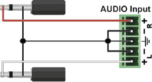


From Balanced Output to Unbalanced Input
|
Phoenix - 2 x 6.3 (1/4") TS |
Phoenix - 2 x RCA |
Phoenix - 3.5 (1/8") TRS |
||
|
|
|
|


From Balanced Output to Balanced Input
|
Phoenix - 2 x 6.3 (1/4") TRS |
Phoenix - 2 x XLR |
2 x 6.3 TRS (1/4") - Phoenix |
||
|
|
|
|
||
|
2 x XLR - Phoenix |
Phoenix - Phoenix |
|||
|
|
|


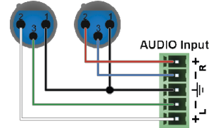

11.6. Maximum Cable Lengths (TPS and TPS2 Boards)
|
Resolution |
Pixel Clock Rate [MHz] |
Cable Lengths |
||
|
CAT5e |
CAT7 |
CAT7 |
||
|
1024x768@60Hz |
65 |
100 m / 130 m* |
90 m / 120 m* |
120 m / 170 m* |
|
1280x720p@60Hz |
73.8 |
100 m / 130 m* |
90 m / 120 m* |
120 m / 170 m* |
|
1920x1080p@60Hz / 24bpp |
148.5 |
100 m / 130 m* |
90 m / 120 m* |
120 m / 170 m* |
|
1920x1200@60Hz |
152.9 |
100 m / NA |
90 m / NA |
120 m / NA |
|
1600x1200@60Hz |
162 |
100 m / NA |
90 m / NA |
120 m / NA |
|
1920x1080@60Hz / 36bpp |
223.6 |
70 m / NA |
70 m / NA |
100 m / NA |
|
3840x2160@30Hz UHD |
297 |
70 m / NA |
70 m / NA |
100 m / NA |
|
4096x2160@30Hz 4K |
297 |
70 m / NA |
70 m / NA |
100 m / NA |
* With Long reach operation mode which supports pixel clock frequencies up to 148.5 MHz.
** When remote powering is used with AWG26 cables, distances are 20% shorter.
To specify the accurate extension distances, please also check the documentation of the connected HDBaseT-compatible device.
11.7. Maximum Cable Lengths (TP Boards)
|
Resolution |
CAT5e UTP |
CAT5e FTP |
CAT6 |
CAT6 |
CAT6 SFTP |
CAT7 SFTP |
|
640x480@60 |
60 m |
60 m |
65 m |
70 m |
70 m |
80 m |
|
800x600@60 |
60 m |
60 m |
65 m |
65 m |
65 m |
75 m |
|
1024x768@60 |
55 m |
55 m |
60 m |
60 m |
60 m |
75 m |
|
1280x720p60 |
55 m |
55 m |
60 m |
60 m |
60 m |
70 m |
|
1280x1024@60 |
50 m |
50 m |
55 m |
60 m |
60 m |
65 m |
|
1400x1050@60 |
45 m |
45 m |
45 m |
55 m |
55 m |
60 m |
|
1600x1200@60 |
30 m |
35 m |
35 m |
45 m |
45 m |
50 m |
|
1920x1080p60 |
30 m |
35 m |
35 m |
45 m |
45 m |
50 m |
|
1920x1200p60 |
30 m |
35 m |
35 m |
45 m |
45 m |
50 m |
11.8. Firmware Release Notes
The list below shows the released firmware packages with important notes.
v3.0.0
Released: 2010-07-14
New feature
▪MX-FR16 support
▪MX-FR80 support
▪MX-DVID-IB, MX-DVID-OB support
▪MX-DVI-TP-IB, MX-DVI-TP-OB support
▪MX-DVI-TP-IB+, MX-DVI-TP-OB+ support
▪MX-OPT-DVI-OB, MX-OPT-DVI-OB-RCLK support (including SX4A and SX4B optical modules)
▪PLL filter is enabled as default in the SI164 chip
▪Implements a test input and a preview output port on the CPU card
▪SMPTE alarm function
▪Advanced EDID management, HDMI support is automatically stripped if needed
▪LCD menu, control board
▪Date and time functions
▪Log errors and basic configuration to the onboard microSD card (FAT filesystem, accessible via Lightware protocol).
▪Monitoring the voltages, fan speeds and power supplies
▪PROTOCOL#2 support
▪Standby mode
3.0.1
Released: 2010-09-16
New feature
▪MX-FR32R support
▪Extended reliability, watchdog + task autorestart
▪MX-HDMI-IB, MX-HDMI-OB support (including audio support)
▪MX-DVI-HDCP-IB, MX-DVI-HDCP-OB support
▪MX-OPT-DVI-IB support
▪MX-DVIDL-IB, MX-DVIDL-OB support
▪HDCP is supported by crosspoint level (HDCP protected signal is routed only to compatible output boards, so mixed cards are supported).
▪HDMI and HDCP support on preview out and test in
▪DualLink signals are supported by crosspoint level (mixed cards are supported).
▪HDCP repeater function support
▪MX-DVI-CPU SCH 2.2 support
▪Extended protocol command set (E.g. diagonal switching)
Bugfix
▪Monitor task dies eventually (very rare). It restarts automatically, so causes no visible problem.
▪Sometimes there is no response to a command (extremely rare).
3.0.11
Released: 2011-04-06
New feature
▪TIPO (Test Input / Preview Output) menu is implemented on the LCD.
Bugfix
▪False fanspeed error bugfix
▪MX-DVI-OPT-OB bugfixes (programming TOSA modules is more robust now.)
▪Controllock button blinking issue bugfix, autotake bugfixes
▪PRECONFTOSA, ROSA commands bugfix
▪Protocol#2 mode freezed when invalid characters were sent.
▪4-line LCD EDID switch issue bugfix
▪Automatic EDID refresh on LCD
▪Preset didn't save the mute state.
▪AD xpoint switching speed up
3.0.3
Released: 2012-12-22
New feature
▪LCD menu improvements
▪MX-DVII-HDCP-IB support
▪Dual protocol mode. (In Protocol#1 mode Protocol#2 commands are also accepted.)
▪MX-DVID-OB SCH 1.1 support
Bugfix
▪Lantronix reset bugfix
▪Preview output HDMI mode is possible now.
3.0.4
Released: 2010-12-23
Bugfix
▪Minor MX-DVII-HDCP-IB bugfixes and improvements
3.0.5
Released: 2010-01-24
New feature
▪Recognising analog video formats by VESA GTF and CVT for MX-DVII-HDCP-IB
▪4-line LCD menu support
▪ELIST command is added. ( Front LCD error list - errors since the last boot-up - is copied.)
▪USB support is added.
Bugfix
▪Xpoint factory default
▪CP panel LED blinking bugfix
▪Preview output lock and mute bugfix
▪Lantronix communication bugfix
3.0.6
Released: 2011-01-31
New feature
▪Coordinated Video Timings, Reduced Blanking support for MX-DVII-HDCP-IB
▪4-line LCD menu improvements
Bugfix
▪Power sum read-out is more redundant.
▪MX-DVII-HDCP-IB factory presets search bugfix
3.0.7
Released: 2011-02-03
New feature
▪HDCP keycounter menu on the LCD
Bugfix
▪MX-DVID-OB port 8 - Vista Spyder incompatibility bugfix.
3.0.8
Released: 2011-02-24
Bugfix
▪Protocol#2 bugfixes (mute and lock)
▪MX-HDMI-OPT-OB LED blinking bugfix
3.0.9
Released: 2011-03-07
New feature
▪:EQ command syntax is more universal: 0 is accepted as auto EQ if discrete eq is used.
Bugfix
▪False fanspeed error bugfix
▪MX-DVI-OPT-OB bugfixes (programming TOSA modules is more robust now.)
3.1.0
Released: 2011-05-09
New feature
▪MXD-HDMI-TP-OB support
▪Newer version of the FAT filesystem library - it is more robust.
▪Input 0 can be connected to anywhere (same as mute).
▪Temperature measurement and show (calibration is needed).
▪DVID-OB signal on/off setting is removed.
Bugfix
▪MX-DVI-OPT-IB, -OB PS (port status) command bugfix
▪FR32 health status format has been changed.
▪MX-DVID-OB CTL3 issue (barco projector compatibility)
3.1.1
Released: 2011-05-24
New feature
▪Error message appears on the LCD in control lock mode if a key is pressed
Bugfix
▪TIPO menu had sometimes shown in FR80 Frame on the LCD.
▪Control Board freezed sometimes. (CB p:14 error)
▪The frame works without MX-SC (LCD panel) now.
▪Front panel take button -input button 1 problem bugfix
▪TIPO menu usage has been improved.
▪MX-DVI-OPT-OB-RCLK LCD menu PLL filter settings is implemented on the 4-line LCD.
▪DVI-I board sent DVI signal in auto mode if a MX-DVI-HDCP-OB, MX-HDMI-OB or MX-HDMI-TP-OB was present.
▪Preview output, MX-HDMI-OB, MX-HDMI-TP-OB, MX-DVI-HDCP-OB, MXD-HDMI-TP-OB outputs discarded audio if the sink device had been connected later than the audio content had been switched to the output.
▪Analog formats signalled in the emulated EDIDs were sometimes detected incorrectly.
3.1.2
Released: 2011-06-08
New feature
▪MXD-UMX-IB support
▪MX-DVIDL-OPT-IB support
▪MX-DVIDL-OPT-OB support
Bugfix
▪If a single-link input was connected to a dual link output then the 2nd link wasn't shut down in AUTO mode.
▪MX-DVI-OPT-OB 2.2 and 2.3 could cause erroneous initialization in some slots.
▪4-line LCD HDCP keycounter had false fail.
▪Countermeasure against 4-line LCD sensitivity to electrostatic discharge events. (First part of the content is read back and checked regularly, in case of discrepancy the content is refreshed.)
3.1.3
Released: 2011-07-20
New feature
▪CARD ACTIVE LED doesn't flash on unknown or unrecognized IO cards in order to help error detection by customers.
▪RS232, LAN and USB interfaces are independent - responses arrive to only the appropriate port, except crosspoint commands. Please refer Lightware-CM-1001 for details.
▪RS232 and LAN interfaces can use different protocol at same time. Please see Lightware-CM-1001 for details.
▪Responses to Protocol#2 switch commands are translated to Lightware protocol on the appropriate interfaces.
▪Protocol setup from LCD menu.
▪"Protocol reset" in Factory reset LCD menu - it restores Lightware protocol on RS232 and LAN.
▪"Set all default" in Factory reset LCD menu - it resets all settings and deletes every change except files on SD card.
▪Improved batch command processing speed if multiple switch commands are sent at the same time.
▪MXD-AUDIO-IB volume handling is modified. The volume can be adjusted/reported between 0-6300 and 0-7800 in 0.01dB steps.
▪Added 3D support for MX-HDMI-IB, MX-DVI-HDCP-IB, MX-HDMI-TP-IB, MX-CPU2 test input and preview output, MX-HDMI-OB, MX-DVI-HDCP-OB, MX-HDMI-TP-OB boards. The detected format is reported back in :HDMI command using the "reserved for future use" byte after colorspace. 1920x1080p, 1280x720p and 640x480p formats are supported in frame-packing, top-bottom, side-by-side mode.
Bugfix
▪Protocol#2 switching commands didn't handle DL outputs at all.
▪Commands were sometimes not recognized, there was no response (about every 10.000th switch).
▪Preset load and Diagonal switch commands didn't consider DualLink ports.
▪Protocol#2 commands were interpreted while using Protocol#1- now only Protocol#1 commands are accepted.
▪Syntax error in a*b% Protocol#2 command reply
▪ISD and OSD responses didn't include the test input/preview output port.
▪More than 32 preset could be saved in FR80R frame from front panel control board. Now it is only 32.
▪CB issue: muted output button didn't blink when the source input button was pressed twice.
▪DVI-I boards sometimes reported HDMI signals when DVI signal was present.
▪MX-DVII-HDCP-IB board treated DVI signal as limited range colorspace. (Colors could be brighter/darker.) Now it is treated as full range - This involves only digital DVI signals.
▪Preview output and HDCP output boards sometimes didn't detect the sent signal - especially with some formats and reversed VSYNC polarity.
▪Downloading a long logfile on RS232 (especially with lower baudrates) or on LAN could cause a false TASK RESET error message.
▪I2C speed has been reduced to 100 kHz during retrying the communication when NACK received from a SiI9134 or a SiI9135.
▪MXD_HDMI_TP_IB support.
▪The default LCD menu page was the main menu structure on the 4-line LCD. Now it is the the Router Status page - similarly to the old 2-line display.
▪PWR_ON command didn't work in MX-FR80 frame after a PWR_OFF command.
▪I2C speed was reduced to achive more robostusness.
▪SignalPresent and EDID menu problem in case of autotake mode has been solved.
3.1.4
Released: 2011-07-25
New feature
▪Command {ST} now reports 'N/A' value instead of '0.00V' for the voltages that are not available in the FR80R frame.
▪Complete status is saved to the SD card after the booting process if an error occurs.
▪Timezones are supported (by adding UTC+nnnn to the end of the time, e.g. 22.07.2011. 15:33:52 UTC+0100)
▪Changing time is logged to the SD card.
▪Batch command processing for switch commands works on both Protocol#1 and Protocol#2.
Bugfix
▪There is no E_S_C when a user EDID is uploaded.
▪Front panel IP reset (ctr lock + output lock) works now
▪MX-DVI-OPT-IB SCH_2.2 laser powers weren't applied after boot.
▪Buffer goes to invalid state in case of buffer overflow
▪USB enumeration failed at boot cycle
▪'No card found' error is only a warning and not a fatal error.
3.1.6
Released: 2011-09-22
New feature
▪Batch commanding applies wait for next command for faster execution.
▪If a power supply looses AC then an error is generated. If it never had AC then no error is generated (only a warning).
▪Error levels sent to communication interfaces can be configured independently to each port by a new command.
▪RS232 baudrate can be adjusted from Lightware protocol by {RS232BAUD=.....} command.
▪FACTORY=GENERAL command reloads the router default general settings (rs232 baudrate, take mode, control lock, communication protocols).
▪Bugfix
▪'PSU not seated/powered' warning is logged only once now.
▪Timezone may have set to UTC+0256 after a firmware upgrade from earlier versions.
▪The input buffers weren't flushed after a front-panel protocol switch. Earlier sent commands may have been executed. Now it is fixed.
▪EDID switch on all inputs caused COMMTASK reset.
▪HDMI LED remained ON when the source was disconnected. The problem occurred when the incoming signal was content protected and the input was switched to multiple output.
▪MX-HDMI-TP-OB: there was no PSC event and the response for {PS} was all '0'
▪4line LCD didn't respond to menu button press in some cases.
▪4line LCD EDID switch menu showed '0' for the destination after startup and there was no 'ALL' option.
▪Battery low voltage warning is logged (and displayed on the LCD) as 'BATTERY LOW' instead of 'VOLTAGE ALERT'.
▪Some error log events were disappeared if the last error was too close in time.
▪:HDCPRESET command may have freezeed the communication
▪HDCP LED sometimes had false blinking on MX-HDMI-IB
▪There was erroneous HDCP handling if more than 20 keys were received from an HDCP capable sink. This may have resulted reboot.
3.1.8
Released: 2011-09-30
New feature
▪MX-DVI-OPT-OB v24 support.
▪Bugfix
▪The response for {VM} command (View Mute state) now starts with "MUT" (not "ALL") according to the product manual.
▪Matrix may have restarted because of internal communication problems in case of DVI-HDCP and HDMI I/O boards.
3.1.9
Released: 2011-10-10
Bugfix
▪The response to the WB# command was different from the one described in the user manual. A number was missing at the end of the line.
3.2.0
Released: 2011-11-02
Bugfix
▪In Protocol#2 the matrix did a switch to all for a single switch command. Now it's fixed.
3.2.2
Released: 2011-11-23
Bugfix
▪Connecting an HDCP capable optical RX/TX to an MX-HDMI-OPT-IB/OB, noisy signal on the communication channel could cause fatal buffer overflow error and restarting of the router. In special cases the router could run an infinite restart loop.
3.2.3
Released: 2011-12-12
New feature
▪Supports MX-3GSDI-IB.
3.2.5
Released: 2012-02-20
Bugfix
▪New standard timing descriptors are applied. Standard resolution list now contains 1024x768@60 and 1920x1080@60 resolutions.
▪Factory EDIDs had a bug - the digital sync was not set properly in the detailed timing descriptor blocks. Sometimes this caused error with analog sources.
▪MX-DVI-OPT-OB 2.0 outputs flashed when a laser enable command was sent to any port.
▪Preview output didn't convert down the deepcolor modes to HDMI 24bit in auto mode if the display didn't support deepcolor.
▪An extra 0-byte length short descriptor was present in the CEA data block. This may have led to incompatibility with some sources.
▪Analog 1920x1200p60 was not recognized due to enabled hsync dejitter filter and high sync detection threshold on the DVI-I board.
▪ASUS EAH3650 video card can send a strange analog format in 1280x720p60 and 1920x1080p60. These resolutions are added to the factory preset list now.
▪The 4-line LCD mismatched the 0dB and Auto EQ options in the MX-DVID-IB settings menu.
▪On the 4 line LCD at the "Switch EDID" menu item it is possible to select factory and user EDIDs, not just dynamic EDIDs.
▪Too many cached HDCP keys could lead to reboot.
▪If an EDID switch happens while the source is reading the data, then the input board could fail (MX-HDMI-IB, MX-DVI-HDCP-IB, MX-HDMI-TP-IB)
3.2.6
Released: 2012-03-01
New feature
▪In case of FR33R the insertion and removal of the PSUs are logged.
Bugfix
▪The matrix could fail to boot in case of wrong RTC.
▪Invalid EDIDs cannot be switched to input ports anymore.
▪The reply for {FC} command now contains the version of the FR33R PWR_SUM board.
▪HDCP handling of preview output in MX-FR80 didn't work properly.
▪MX-HDMI-OPT-IB didn't detect if the link was terminated. (The bug appeared in 3.1.6)
3.2.7
Released: 2012-05-30
New feature
▪Support for MX-FR33L
▪Pixel phase can be adjusted and saved with SMPTE compliant analog component/rgbhv incoming signals.
▪Saving and loading of a full matrix config is now possible. It can be controlled with the LCD menu (2 and 4 line LCD) and the lightware protocol.
▪Serial command passthru (receive and send) on MX-HDMI-OPT-IB/OB cards.
▪Control commands are not uppercased any more. This way lowercase characters can be used for example with serial command passthru and I/O names. Control commands should be still recognized with lowercase or uppercase characters.
Bugfix
▪Only the first two channels of mulitchannel PCM audio formats were passed by the router. Now up to 8 channels up to 192kHz are supported. Affected cards and ports: MX-HDMI-IB/OB, MX-DVI-HDCP-IB/OB, MX-HDMI-TP-IB/OB and CPU preview output/test input. When multichannel PCM is switched to an MX-HDMI-OB card, the front right and front left channels will be present on the SPDIF output connector.
▪Audio infoframes were lost when the display was turned off and on again (or removed and plugged in again). Affected cards and ports: MX-HDMI-IB/OB, MX-DVI-HDCP-IB/OB, MX-HDMI-TP-IB/OB and CPU preview output/test input.
▪SHUTDOWN time was invalid in some cases. now it's fixed.
▪Some displays (only known example is DELLU2410) didn't play audio correctly, if the signal was originated from an MX-DVII-HDCP-IB or an MXD-UMX-IB board. The problem persisted at 148.5/1.001 and 74.25/1.001 pixel clock frequencies.
▪The matrix rebooted after a while if a display continuously pulled the hot-plug up and down.
3.2.8
Released: 2012-06-01
Bugfix
▪In the MX-FR80R during the boot sequence the matrix reported a missing PSU as an error. It was a false alarm because it is an error only when the PSU is removed during operation. This false alarm is fixed.
3.3.0
Released: 2012-08-16
New feature
▪EDID reading is supported on both MX-HDMI-OPT-OB and MX-HDMI-OPT-IB card. Their behaviour is same as other cards now (dynamic edids, edid switching, etc.)
▪RS232 over fiber feature can be disabled per port basis. The default state is disabled. EDID is read only on the output port, if the serial passthru is disabled.
▪MX-HDMI-3D-IB and MX-HDMI-3D-OB are supported.
▪Omron SX51TX optical transmitter module (MX-HDMI-OPT-OB) has 0 default value for "waveform select" as this proved to result better performance on shorter cables.
Bugfix
▪Turning the laser quickly on/off on the HDMI-OPT-OB card from the controlsw resulted in connection loss with the HDMI-OPT- receiver device.
▪Sometimes random 0x03 charachters were sent to odd MX-HDMI-OPT-OB serial ports.
3.3.1
Released: 2012-10-19
New feature
▪MX-DVI-OPT-OB-RCLK SCH_2.2 support
▪MX-3GSDI-IB now supports 3GSDI Level B signals: 1080p 50Hz and 60Hz
▪Bugfix
▪If an output was connected to "input 0" (disconnected), then it was switched to input 1 after a front panel-switching
▪If the LAN used Protocol#2 and RS232 used LW protocol, then the responses for the front panel switches were not sent to the RS232 port.
▪Connecting an output to input 0 (disconnected) when at least one dual link input card was present in the router may have caused fatal crosspoint switching error.
▪The Validity bit was set wrong in audio sample packets SB6 byte when PCM audio was transmitted. Affected cards: MX-HDMI-IB/OB, MX-DVI-HDCP-IB/OB, MX-HDMI-TP-IB/OB, Test input, Preview output.
▪If MX-HDMI-IB/MX-DVI-HDCP-IB/MX-HDMI-TP-IB/Test input was used, then the SPDIF outputs sent copyrighted (copy protected) material. Now the content protection is turned off on SPDIF outputs on the MX-HDMI-OB card.
▪When MXD-UMX-IB digitalized an analog audio signal, then the SPDIF stream was marked as professional application. This wasn't right for some professional SPDIF receivers.
▪MXD-HDMI-3D-IB/OB marked the digitalized analog audio as professional copyrighted material. Now it is marked as consumer non-protected material because this prevents some SPDIF interoperability issues.
▪Digital signals with <40px back porch had sometimes strange recolor effects with MX-DVII-IB and MXD-UMX-IB board.
▪If the MX-DVII-IB or the MXD-UMX-IB has been received HDMI YUV (444 or 422) signal and the user set the input video signal source with the :DVII command again to auto or digital mode (DVII command first parameter is S or D), then the image got greenish tint. This was because using incorrect YUV-RGB color conversion matrix.
▪If the MXD-UMX-IB has been embedded audio from the audio addon panel into the DVI/HDMI stream, and the user set the input video signal source with the :DVII command again to auto or digital mode (DVII command first parameter is S or D), then the image was blinking for a few seconds (and therefore audio was also muted for a while). This was because the TMDS clock was disabled while reapplying some settings. Now this flashing and audio dropout is eliminated.
▪MX-HDMI-3D-OB and MX-HDMI-3D-IB - several bugfixes related to test pattern modes, HDCP and infoframes.
▪If the IP address starts with 0 it is not displayed from now. e.g.: before this fix: "IP: 192.168.002.068" from now: "IP: 192.168.2.68"
▪DVIDL-IB EQ settins worked only for the first two output and port numbers were misindexed.
▪fixed MX-3GSDI-IB audio crosspoint initialization, audio channel status and audio infoframe content.
▪MX-HDMI-3D-IB didn't work well with 4x20 character LCD display
3.3.2
Released: 2012-11-12
Bugfix
▪MX-3GSDI-IB bugfix: the card sent GS2971 alert sometimes, when video signal was detected.
3.3.3
Released: 2013-01-17
New feature
▪CPU SCH version is displayed in the LCD menu (among the Installed cards - both LCD types are supported)
▪The serial number of the CPU and I/O boards are saved to the SD card log during the boot process.
3.3.4
Released: 2013-01-28
Bugfix
▪The image was shifted one pixel to the right with digital signals. Affected cards: MX-DVII-HDCP-IB, MXD-UMX-IB
3.3.5
Released: 2013-03-04
Bugfix
▪IO card SN numbers may cause stability issues.
3.3.6
Released: 2013-05-23
New feature
▪MX-TPS-OB, MX-TPS-OB-A, MX-TPS-OB-S support (incl. serial passthru and ethernet functions)
▪MX-TPS-IB, MX-TPS-IB-A, MX-TPS-IB-S support (incl. serial passthru and ethernet functions)
▪File uploading to SD card through Lightware protocol. (needed for TPS fw upgrade)
Bugfix
▪The LCD screen didn't show the analog audio options for the MX-HDMI-3D
▪If a dynamic EDID memory slot had been empty and new EDID was read from one output, then the output validity table was showed as being invalid EDID after reading the EDID header until the first reboot.
▪The audio sample frequency was unstable at 1080p60, this may have resulted crunches on the S/PDIF output with DVII input.
▪HDCP keycounter sometimes resulted with 0 key with certain devices due to a short timeout. Now this is fixed.
▪The MX-DVII-IB and the MX-UMX-IB boards sometimes didn't detect the 36 bpp - 24 bpp deep color change, and remained in 36bpp mode.
▪MX-DVII-IB, MXD-UMX-IB: SPD Infoframe was sent with wrong header, could cause issues with deep color signal. Stored settings block was too large on these cards.
▪If an MX-HDMI-3D-IB card was present at the 1st input slot and any output was connected to the 0th input (ie. disconnected), then the matrix has coninously rebooted.
▪A noisy incoming signal may disable input ports on MX-HDMI-IB, MX-DVI-HDCP-IB, MX-HDMI-TP-IB and CPU test input (signals were detected appropriately but not forwarded to the crosspoint). The only solution was to restart the whole router, however the issue has appeared very rare. This issue is fixed now.
3.3.7
Released: 2013-08-22
New feature
▪Temperature sensor readbacks on the MX-TPS-IB/OB cards.
▪Logfile reading speed has been increased a lot. LAN connection speed is around 5kbyte/sec , while the RS232 port utilizes the full bandwidth (depending on the actual baudrate)
▪Errorlevel handling is modified: recoverable issues will not display on the LCD and they will not trigger the alarm LED.
▪Ethernet can be disabled or enabled per port basis on TPS-IB/OB cards
▪HDBase-T HDCD database is used to recognise remote devices
▪The minimum assertion time for hotplug line is 1.5 sec on the MX-HDMI-IB, MX-HDMI-TP-IB, MX-DVI-HDCP-IB, MX-DVII-IB, MXD-UMX-IB, MX-HDMI-3D-IB (and variants), MX-TPS-IB (and variants) cards and test input port. This is 15 times greater than the required minimum by the standard. The intention of this extra long HPD pulse is prevent the non-standard devices to miss the hpd event.
Bugfix
▪A false "SBTB error" message has appeared on the LCD screen after boot if at least one MX-DVIDL-OB card was installed in the frame. This issue persisted only with 3.3.6
▪Changing audio mode on a port could have an effect on the adjacent port's audio mode. Affected cards: MX-HDMI-3D-IB, MX-HDMI-3D-OB, MX-TPS-IB, MX-TPS-OB.
▪When the source stopped sending audio in HDMI stream, the ports did not detect it correctly in some cases, and still reported embedded audio. Affected cards: MX-HDMI-3D-IB, MX-HDMI-3D-OB, MX-TPS-IB, MX-TPS-OB
▪Factory default test pattern changed from solid black to color bar. Affected cards: MX-HDMI-3D-IB, MX-HDMI-3D-OB, MX-TPS-IB, MX-TPS-OB
▪Deep color problem with DELL U2410 fixed. Affected cards: MX-HDMI-3D-IB, MX-HDMI-3D-OB, MX-TPS-IB, MX-TPS-OB
▪When an HDMI 1.3 output was muted after receiving deep color signal, low resolution signals (below 41 MHz TMDS clock) was not detected by the port after unmute. Fixed. Affected cards: MX-HDMI-OB, MX-DVI-HDCP-OB, MX-HDMI-TP-OB, MX-CPU2 (Preview output).
▪When no embedded audio was present on a port, noise was detected on S/PDIF outputs, which were used to deembed audio. Fixed on MX-HDMI-3D-IB-S, MX-HDMI-3D-OB-S, MX-HDMI-OB, MX-TPS-IB-S, MX-TPS-OB-S.
▪SPDIF clicking/popping noise bug fix. When there was no audio sample packet in the stream (but ACR packets were still present), the MX-HDMI-OB, MX-DVI-HDCP-OB and preview output have sent a 53Khz invalid SPDIF signal. This caused a clicking noise with some AV receiver.
▪Audio embedding fixed (it failed in some cases, when the user changed Audio mode to Embed from aux audio). Affected cards: MX-HDMI-3D-IB, MX-HDMI-3D-OB, MX-TPS-IB, MX-TPS-OB
3.3.8
Released: 2013-10-01
Bugfix
▪PWR_x commands responded "Invalid command" if sent to frame that is smaller than 80x80. These commands are only valid for the 80x80 frame.
▪If input signal was present on a SII9575 port and test pattern mode was changed from "Off" to "No signal mode", SII9575 output had been turned off for a short period unnecessarily. Fixed. Affected cards: MX-HDMI-3D-IB, MX-HDMI-3D-OB, MX-TPS-IB, MX-TPS-OB.
▪Deembedded audio outputs (analog, S/PDIF) become stable more quickly after input signal is changed. Affected cards: MX-HDMI-OB, MX-TPS-OB-S, MX-TPS-OB-A, MX-HDMI-3D-OB-S, MX-HDMI-3D-OB-A.
▪Firmware v3.3.7 sometimes rebooted with 2 or 4 line LCD display.
▪The cycle testpattern has stopped sometimes for a few minutes.
▪If an error happened during the booting process, there was no alert displayed on the LCD screen (however the event has been logged).
▪If the errorlog menu was active on the 4-line LCD screen, then a new incoming alert may confuse the lines on the LCD screen.
▪Lightware simple protocol mode (P_3) could hang if an unknown command had been received.
▪When the USB connector was used from the Matrix Controller software, every incoming charachter was capitalized. This lead to unexpected results while using the ROF (RS232 over fiber / TPS) commands.
▪Error log downloading over USB was bugous.
3.3.9
Released: 2013-10-22
Bugfix
▪Display Range Limits Descriptor was not correct in factory EDIDs (except universal EDIDs).
3.4.0
Released: 2014-01-13
New feature
▪MX-HDMI-OPT-OB-R support has been added.
▪New factory EDIDs have been added: 3D compliant, 4K, 4K universal EDIDs and most often used pc graphics resolutions with audio support.
Bugfix
▪The serial port extension sometimes transmitted/received bugous data on the TPS boards.
▪If one or more MX-TPS-IB or MX-TPS-OB (including audio addon versions) were installed in the frame, sometimes a false flashing "PCA9673" error appeared on the LCD screen.
▪When DVII input board was used with MX-HDMI-3D-OB or MX-TPS-OB, the output ports could measure strange resolution or could not detect the incoming signal, if the DVII input changed from no sync screen to incoming signal. Fixed.
▪Green sparks could appear in the output signal of MX-HDMI-3D-OB, if the input signal was coming from MX-HDMI-3D-IB and was switched between 1080p and 480p by the crosspoint.
3.4.1
Released: 2014-03-31
Bugfix
▪Some monitors that do not terminate the TMDS lines in standby mode, could not wake up from this state, when input signal was connected through MX-HDMI-3D-OB or MX-TPS-OB. This issue is now fixed by powering up the output ports not only when TMDS termination is present, but also after a hotplug event. Affected cards: MX-HDMI-3D-OB, MX-TPS-OB.
▪4line LCD - View EDID menu froze the LCD task if there were no IO cards in the matrix.
▪4line LCD - FR80 - View EDID did not show the 81st input and output.
▪4line LCD - View EDID - Dynamic EDIDs was not displayed if there were no input cards in the same numbered slot (the problem was checking the input cards instead of the output cards)
▪Too long lines in the error log may have disrupted the log reading if special charachters were used.
▪The text of the test pattern generator clock menu on the LCD screen was disambigous.
▪There was no error message if SX51 was configured to SX4.
▪4-line LCD - The S/N number of the output cards were not shown in the card information menu.
3.4.2
Released: 2014-05-26
New feature
▪MX-HDMI-OPT-OB supports HDCP auto/always function now.
3.4.3
Released: 2014-06-27
Bugfix
▪A rare ADM1063 false alarm has appeared on the LCD or sometimes the internal voltages were reported improperly. Affected frame: MX-FR80
3.4.4
Released: 2014-10-08
New feature
▪UMX-TPS devices handle the command channel even in disabled receive mode, serial packets are discarded.
▪IP configuration via RS-232.
▪Logging data extended, if VS100 holds I2C SCL line down. VS100_getHpdStatus function added (previously this register was checked in handler periodically, but it was removed in order to reduce the number of remote read transactions to prevent VS100 I2C lockdowns).
Bugfix
▪TPS write functions fixed in disabled receive mode.
▪VSNACK and SII9575 errors fixed on MX-TPS-IB and MX-TPS-OB.
3.4.5
Released: 2015-01-28
New feature
▪MX-3GSDI-IB converts every video signal to RGB444.
Bugfix
▪Plugging a monitor into the FR80's Preview Output caused reloading of factory default EDID to all inputs.
▪Alphanumeric charachters in the factory EDIDs (like display name field) were not padded properly.
▪Factory default IP can be set with controlboard buttons.
▪Factory EDID revision number has been set to 1.3 instead of 1.4 now. This may prevent compatibility issues (usually the source didn't see the connected device as audio capable) with old graphics card drivers.
▪Analog YUV support has been removed from the basic EDID structures of factory EDIDs.
▪From now on MX-DVII-HDCP-IB and MXD-UMX-IB cards always send 24bpp signal into the crosspoint switch. The 36bpp signals caused signal integrity problems in some rare conditions which could result in audio popping noise.
3.4.6
Released: 2015-07-27
New feature
▪Added support for MX-HDMI-3D-STEREO-ADDON v20.
▪Added support for MX-TPS2-IB/OB (and variants).
▪If the temperature of the TPS or TPS2 card increases above 80C, it is logged into the SD card.
▪Added support for MX-3GSDI-IB v20.
Bugfix
▪Some residual power from the output cards (from the connected sink devices) could keep the CPU alive in MX-FR80 and MX-FR65 frames even after removing the AC cords. This resulted false alarms on the LCD and in the log files. This condition is detected and handled now.
▪MX-HDMI-3D-OB and MX-TPS-OB could not handle if one of the DDC lines was broken. It could cause VTASK RESET and SII9575 errors. Fixed.
▪MX-FR80 logged a false "MTRI setXpoint" error after crosspoint switching.
▪Improved error notifications on the 2 and 4 line LCD.
▪AVI Infoframes were set improperly on MX-3GSDI-IB. This caused random video drops with some displays.
▪Emulated EDID is updated now if the source user EDID is changed.
▪The appropriate validity flag is set when a user EDID changes.
3.4.7
Released: 2015-08-14
Bugfix
▪Fixed MXSC (Status board) CPU LIVE LED blinking.
3.4.8
Released: 2015-12-01
New feature
▪Added support for MX-AUDIO-OB-A board.
▪4K 60Hz 4:2:0 EDID has been added as 113th Factory EDID.
Bugfix
▪4K 60Hz 4:2:0 resolution was falsely reported back as 1920x2160p60
3.4.9
Released: 2016-04-22
New feature
▪Added support for MX-4TPS2-4HDMI-IB cards.
Bugfix
▪[MXFR-3005] MX-3GSDI-IB did not work if an MX-HDMI-OPT-OB was in the matrix.
3.5.0
Released: 2017-01-16
New feature
▪Support for Omron (Inneos) 'F' type modules (DVI-OPT-OB and HDMI-OPT-OB)
Bugfix
▪Cyviz XPO4 HDCP error fixed: SII9575 stopped HDCP authentication, if the sink reported all 0 bytes as KSV by mistake.
▪HDMI-3D-OB (and TPS-OB) default audio config changed to 'E' (passthrough and deembed)
3.5.1
Released: 2017-04-20
New feature
▪Added support for MX-4TPS2-4HDMI-OB cards.
3.5.2
Released: 2017-04-25
Bugfix
▪Response for VC command fixed for dual-link outputs if the output is routed to input 0 (mute). Before: {0@1} {vc} (ALL 00 01) After fix: {0@1}{vc} (ALL 00 00)
3.5.3
Released: 2017-07-17
New feature
▪Improvements for manufacturing tests.
3.5.4
Released: 2017-07-17
Bugfix
▪Improves stability with MX-3GSDI-IB.
3.5.5
Released: 2018-10-09
Bugfix
▪Improved the final manufacturing test processes.
3.5.6
Released: 2019-03-26
New feature
▪Added support for MX-DVI-4K-IB and MX-DVI-4K-OB boards.
v3.5.7b8
Release date: 2020-01-30
New feature:
▪Support for new TPS devices.
▪New product supports: MX-FR9R, MX-FR17R
v3.5.8b1
Release date: 2020-03-10
Bugfix:
▪Minor bugfix for MX-TPS2 and MX-4TPS2 cards.
11.9.1. MX-FR80R and MX-FR65R


11.9.2. MX-FR33R

11.9.3. MX-FR33L

11.9.4. MX-FR17 and FR17R, MX-FR9 and FR9R
INFO:Certain parts are different in models mentioned above, but the external dimensions are the same.

11.10. ASCII Table
The most common used characters are highlighted in blue.
|
Dec |
Hex |
Char |
Dec |
Hex |
Char |
Dec |
Hex |
Char |
Dec |
Hex |
Char |
|
0 |
00 |
[NUL] |
32 |
20 |
[Space] |
64 |
40 |
@ |
96 |
60 |
` |
|
1 |
01 |
[SOH] |
33 |
21 |
! |
65 |
41 |
A |
97 |
61 |
a |
|
2 |
02 |
[STX] |
34 |
22 |
" |
66 |
42 |
B |
98 |
62 |
b |
|
3 |
03 |
[ETX] |
35 |
23 |
# |
67 |
43 |
C |
99 |
63 |
c |
|
4 |
04 |
[EOT] |
36 |
24 |
$ |
68 |
44 |
D |
100 |
64 |
d |
|
5 |
05 |
[ENQ] |
37 |
25 |
% |
69 |
45 |
E |
101 |
65 |
e |
|
6 |
06 |
[ACK] |
38 |
26 |
& |
70 |
46 |
F |
102 |
66 |
f |
|
7 |
07 |
[BEL] |
39 |
27 |
' |
71 |
47 |
G |
103 |
67 |
g |
|
8 |
08 |
[BS] |
40 |
28 |
( |
72 |
48 |
H |
104 |
68 |
h |
|
9 |
09 |
[TAB] |
41 |
29 |
) |
73 |
49 |
I |
105 |
69 |
i |
|
10 |
0A |
[LF] |
42 |
2A |
* |
74 |
4A |
J |
106 |
6A |
j |
|
11 |
0B |
[VT] |
43 |
2B |
+ |
75 |
4B |
K |
107 |
6B |
k |
|
12 |
0C |
[FF] |
44 |
2C |
, |
76 |
4C |
L |
108 |
6C |
l |
|
13 |
0D |
[CR] |
45 |
2D |
- |
77 |
4D |
M |
109 |
6D |
m |
|
14 |
0E |
[SOH] |
46 |
2E |
. |
78 |
4E |
N |
110 |
6E |
n |
|
15 |
0F |
[SI] |
47 |
2F |
/ |
79 |
4F |
O |
111 |
6F |
o |
|
16 |
10 |
[DLE] |
48 |
30 |
0 |
80 |
50 |
P |
112 |
70 |
p |
|
17 |
11 |
[DC1] |
49 |
31 |
1 |
81 |
51 |
Q |
113 |
71 |
q |
|
18 |
12 |
[DC2] |
50 |
32 |
2 |
82 |
52 |
R |
114 |
72 |
r |
|
19 |
13 |
[DC3] |
51 |
33 |
3 |
83 |
53 |
S |
115 |
73 |
s |
|
20 |
14 |
[DC4] |
52 |
34 |
4 |
84 |
54 |
T |
116 |
74 |
t |
|
21 |
15 |
[NAK] |
53 |
35 |
5 |
85 |
55 |
U |
117 |
75 |
u |
|
22 |
16 |
[SYN] |
54 |
36 |
6 |
86 |
56 |
V |
118 |
76 |
v |
|
23 |
17 |
[ETB] |
55 |
37 |
7 |
87 |
57 |
W |
119 |
77 |
w |
|
24 |
18 |
[CAN] |
56 |
38 |
8 |
88 |
58 |
X |
120 |
78 |
x |
|
25 |
19 |
[EM] |
57 |
39 |
9 |
89 |
59 |
Y |
121 |
79 |
y |
|
26 |
1A |
[SUB] |
58 |
3A |
: |
90 |
5A |
Z |
122 |
7A |
z |
|
27 |
1B |
[ESC] |
59 |
3B |
; |
91 |
5B |
[ |
123 |
7B |
{ |
|
28 |
1C |
[FS] |
60 |
3C |
< |
92 |
5C |
\ |
124 |
7C |
| |
|
29 |
1D |
[GS] |
61 |
3D |
= |
93 |
5D |
] |
125 |
7D |
} |
|
30 |
1E |
[RS] |
62 |
3E |
> |
94 |
5E |
^ |
126 |
7E |
~ |
|
31 |
1F |
[US] |
63 |
3F |
? |
95 |
5F |
_ |
127 |
7F |
[Del] |
11.11. Hashtag Keyword List
This user's manual contains keywords with hashtags (#) to help you find the relevant information as quick as possible.
The format of the keywords is the following:
#<keyword>
The usage of the keywords: use the Search function (Ctrl+F / Cmd+F) of your PDF reader application, type the # (hashtag) character and the wished keyword.
The #new special keyword indicates a new feature/function that has just appeared in the latest firmware or software version.
Example
#dhcp
This keyword is placed at the DHCP (dynamic IP address) setting in the front panel operation, the Lightware Device Controller (LDC) and the LW2 programmer's reference section.
The following list contains all hashtag keywords placed in the document with a short description belonging to them. The list is in alphabetical order by the hashtag keywords.
|
Hashtag Keyword |
Description |
|
#analogaudio |
Analog audio related settings |
|
#audio |
Audio related settings |
|
#autotakemode |
Autotake mode |
|
#builtinweb |
Built-in web |
|
#button |
Front panel button operations |
|
#controllock |
Front panel control lock |
|
#controlprotocol |
Control protocol (LW2 / Control protocol #2) query |
|
#crosspoint |
Crosspoint switch setting |
|
#date |
Date setting |
|
#devicelabel |
Product type |
|
#dhcp |
Dynamic IP address (DHCP) setting |
|
#edid |
EDID related settings |
|
#firmwareversion |
Firmware version query |
|
#framedetector |
Frame detector in LDC/built-in web |
|
#gain |
Gain (for analog audio) setting |
|
#gridview |
Grid view in LDC |
|
#hdcp |
HDCP-encryption related setting |
|
#ipaddress |
IP address related settings |
|
#label |
Device label |
|
#lock |
Port lock settings |
|
#mute |
Port mute setting |
|
#network |
Network (IP address) related settings |
|
#nosyncscreen |
Test pattern (no sync screen) settings |
|
#outputlock |
Front panel output lock |
|
#power |
Power supply and redundancy related information |
|
#power5v |
HDMI 5V power mode setting |
|
#preset |
Preset related settings |
|
#reboot |
Restarting the device |
|
#redundancy |
Power supply and redundancy related information |
|
#reset |
Restarting the device |
|
#restart |
Restarting the device |
|
#rs232 |
RS-232 related settings |
|
#rs-232 |
RS-232 related settings |
|
#serial |
RS-232 related settings |
|
#switch |
Crosspoint switch setting |
|
#takemode |
Take mode |
|
#terminal |
Advanced view window |
|
#testpattern |
Test pattern (no sync screen) settings |
|
#tileview |
Tile view in LDC |
|
#time |
Time setting |
|
#unlock |
Port unlock settings |
|
#unmute |
Port unmute setting |
|
#volume |
Volume (for analog audio) setting |
|
#web |
Built-in web |

11.12. Further Information
Limited Warranty Statement
1. Lightware Visual Engineering PLC (Lightware) warrants to all trade and end user customers that any Lightware product purchased will be free from manufacturing defects in both material and workmanship for three (3) years from purchase unless stated otherwise below. The warranty period will begin on the latest possible date where proof of purchase/delivery can be provided by the customer. In the event that no proof can be provided (empty ‘Date of purchase’ field or a copy of invoice), the warranty period will begin from the point of delivery from Lightware.
1.1. 25G and MODEX product series will be subject to a seven (7) year warranty period under the same terms as outlined in this document.
1.2. If during the first three (3) months of purchase, the customer is unhappy with any aspect of a Lightware product, Lightware will accept a return for full credit.
1.3. Any product that fails in the first six (6) months of the warranty period will automatically be eligible for replacement and advanced replacement where available. Any replacements provided will be warranted for the remainder of the original unit’s warranty period.
1.4. Product failures from six (6) months to the end of the warranty period will either be repaired or replaced at the discretion of Lightware. If Lightware chooses to replace the product then the replacement will be warranted for the remainder of the original unit’s warranty period.
2. The above-stated warranty and procedures will not apply to any product that has been:
2.1. Modified, repaired or altered by anyone other than a certified Lightware engineer unless expressly agreed beforehand.
2.2. Used in any application other than that for which it was intended.
2.3. Subjected to any mechanical or electrical abuse or accidental damage.
2.4. Any costs incurred for repair/replacement of goods that fall into the above categories (2.1., 2.2., 2.3.) will be borne by the customer at a pre-agreed figure.
3. All products to be returned to Lightware require a return material authorization number (RMA) prior to shipment and this number must be clearly marked on the box. If an RMA number is not obtained or is not clearly marked on the box, Lightware will refuse the shipment.
3.1. The customer will be responsible for in-bound and Lightware will be responsible for out-bound shipping costs.
3.2. Newly repaired or replaced products will be warranted to the end of the originally purchased products warranty period.
Document Revision History
|
Rev. |
Release date |
Changes |
Editor |
|
1.0 |
19-10-2012 |
Initial version |
Tamas Lehel |
|
. . . |
|||
|
4.4 |
03-05-2023 |
Page-setting correction. |
Laszlo Zsedenyi |
|
4.5 |
12-12-2023 |
Specifications updated |
Tamas Forgacs |
+36 1 255 3810
Lightware Visual Engineering PLC.
Peterdy 15, Budapest H-1071, Hungary
©2024 Lightware Visual Engineering. All rights reserved. All trademarks mentioned are the property of their respective owners. Specifications subject to change without notice.