Thank you for choosing Lightware’s MX2M series matrix switchers. In the first chapter we would like to introduce the device, highlighting the most important features in the sections listed below:
1.1. Description

MX2M-FR24R is a member of the Lightware MX2 modular matrix switcher series, supporting uncompressed 4K UHD resolution at 60Hz with 4:4:4 sampling pattern and with down-conversion capabilities to 4:2:2, supporting HDCP 1.x and 2.3, 3D, Dolby TrueHD and DTS-HD Master Audio. The non-blocking matrix architecture distributes and switches 24 video signals to 24 outputs, distributed along six 4-port boards respectively per direction.
This versatile and customizable device is suitable for various types of applications, the actual application determining the choice of input and output boards to be included in the frame. It is a perfect choice for installations where a huge number of HDMI 2.0 compliant and other types of input and output video ports are required, including HDMI 2.0 and extension through fiber.
Besides the six 4-port input and six 4-port output video boards, there are four low speed installable slots for audio and other low speed signal connectivity.
Control for connected extenders is served by Ethernet layer. The Ethernet layer can also be used for IP extension, as well as for command injection for IR and serial control by third party devices.
For operation safety, power redundancy is available, and PSU drawers are field-exchangeable for ease of maintenance. The device also supports various IT security standards.
Model Denomination

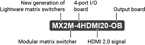
About the Serial Number
Lightware devices contain a label indicating the unique serial number of the product. The structure is the following:

The following table shows detailed information about the different frame types of the MX2M series matrix switchers.
|
Frame type |
Equipment |
PSU redundancy |
Remote power capability |
Nr. of device-powered I/O boards |
|
MX2M-FR24R-F |
Equipped with 1 pcs MX2M-PSU-500-F power drawer. |
|
|
16 |
|
MX2M-FR24R-RF |
Equipped with 2 pcs MX2M-PSU-500-F power drawers. |
|
|
16 |
|
MX2M-FR24R-FP |
Equipped with 1 pcs MX2M-PSU-1250-FP power drawer. |
|
|
16 |
|
MX2M-FR24R-RFP |
Equipped with 2 pcs MX2M-PSU-1250-FP power drawers. |
|
|
16 |


1.3. Box Contents
The following table describes all supplied and optional accessories of the MX2M series frames and I/O boards. The optional (not-supplied) accessories can be purchased separately; please contact sales@lightware.com.
|
Supplied device |
Supplied accessories |
||||||

|
.png)
|

|

|

|

|
||
|
Matrix switcher frame with rack mounting ears |
IEC power cable |
UTP patch cable (3 m) |
Handle pair with 4 pcs M5 flat head screws |
Phoenix® Combicon 5-pole connector |
Safety & Warranty Info; Quick Start Guide |
||
|
Frames |
MX2M-FR24R-F |
|
|
|
|
|
|
|
MX2M-FR24R-RF |
|
|
|
|
|
|
|
|
MX2M-FR24R-FP |
|
|
|
|
|
|
|
|
MX2M-FR24R-RFP |
|
|
|
|
|
|
|
|
I/O board |
MX2M-AUX-8AUDIO |
|
|
|
|
|
|


1.4. Features
MX2M Hybrid Frame

|
4K Video without Compression |
|
HDMI 2.0 signal switching with 4k@60Hz and RGB 4:4:4 color space, 18 Gbit/sec bandwidth. |
|

|
Non-blocking Crosspoint Matrix Architecture |
|
The router allows any input to be switched to any output or more outputs simultaneously. |
|

|
Hybrid Modular System |
|
Custom I/O sizes with several types of input and output boards give the flexibility for interfacing with different video sources and displays. |
|

|
Hot Swappable I/O Boards |
|
MX2M series I/O boards and the PSU drawers can be exchanged anytime without powering off the matrix router. |
|

|
Maximum AV Compatibility |
|
The matrix is compatible with the latest HDMI 2.0 standard, as well as with HDMI 1.x and DVI 1.0 standards. |
|
|
|
Multilayer Signal Routing |
|
In the MX2M product range Lightware added a third dimension of signal routing, the Media Layers, which provide the flexibility and freedom of independent signal switching. MX2M Hybrid frames manage as many Media Layers as signal types: there are as many individual routers as incorporated signal types. |
|

|
HDCP Compliant |
|
MX2M matrix switcher fulfills the HDCP standard. HDCP capability on the HDMI inputs can be disabled when non-protected content is extended. |
|

|
No Signal Latency With Zero Frame Delay |
|
The signal management architecture ensures that there is no delay added between the input and the output. |
|

|
Advanced EDID Management |
|
The user can emulate any EDID on the inputs independently, read out and store any attached monitor's EDID in the internal memory locations. |
|
|
|
Pixel Accurate Reclocking |
|
Each output has a clean, jitter free signal, eliminating signal instability and distortion caused by long cables or connector reflections on the input side. |
|

|
Frame Detector and Signal Analysis |
|
The exact video and audio signal format can be determined such as timing, frequencies, scan mode, HDCP encryption, color range, color space and audio sample rate. |
|

|
Reliability and Redundancy |
|
At Lightware we build our reputation and pay special attention on designing, developing and making truly reliable products. MX2M hybrid line frames have hot-swappable redundant power supplies. These frames were designed for mission critical operations where redundancy is key and high reliability is required. The redundant hot-swappable power drawers accept AC voltages from 100 to 240 Volts with 50 or 60 Hz line frequency on standard IEC connector. |
|

|
Non-Volatile Memory |
|
The matrix router starts with its latest configuration settings when powered on or after a power failure. Every setting is stored in a non-volatile memory. |
|

|
Graphic Display and Rotary Jog Dial Control Knob |
|
Easy setting and menu navigation are assured by the color graphic display and the comfortable jog dial control. |
|

|
Built-in Website |
|
Easy access from a web browser to control and configure the matrix in systems where the software is not allowed to be installed. |
|

|
Ethernet Control |
|
Multiple simultaneous TCP/IP connections are available with simple ASCII based protocol for controlling and configuring the matrix router. |
|

|
USB Control |
|
Easily accessible front panel USB configuration port. |
|

|
RS-232 Control |
|
Simple ASCII-based protocol can be used for switching, preset calling, status request, etc. |
MX2M-4HDMI20 Series Boards

|
4K Video without Compression |
|
HDMI 2.0 signal switching with 4k@60Hz and RGB 4:4:4 color space, 18 Gbit/sec bandwidth. |
|
|
|
Consumer Electronics Control |
|
Supports transmitting standard CEC commands in order to remote control the source or sink device. |
MX2M-DH-4DP12-IB Board
|
|
4K Video without Compression |
|
DisplayPort 1.2 signal switching with 4k@60Hz and RGB 4:4:4 color space, 18 Gbit/sec bandwidth. |
|

|
Restart Link Training |
|
Allows the DisplayPort Link Training to be restarted in case of no signal or bad quality, without unplugging the cable. |
|

|
DisplayPort Diagnostics and Management |
|
Provides detailed DisplayPort-specific connectivity information: AUX handshaking, 1/2/4 lane count, RBR/HBR/HBR2 datarates. DisplayPort AUX-channel analyzer helps debugging and analyzing handshaking problems. |
MX2M-4OPTJ Series Boards
|
|
4K Video without Compression |
|
HDMI 2.0 signal switching with 4k@60Hz and RGB 4:4:4 color space, 18 Gbit/sec bandwidth. |
|

|
Single Fiber Technology |
|
HDMI 2.0 signal with 4k@60Hz up to 18 Gbps signal transmission over a single fiber cable. The MX2M-4OPTJ series boards makes possible direct connection with the fully compatible HDMI20-OPTJ-90 series fiber transmitters and receivers. |
|

|
Consumer Electronics Control |
|
Supports transmitting standard CEC commands in order to remote control the source or sink device. |
MX2M-4TPX Series Boards
|
|
4K Video without Compression |
|
HDMI 2.0 signal switching with 4k@60Hz and RGB 4:4:4 color space over 10 Gbit/sec bandwidth. |
|

|
SDVoETM Compatibility |
|
The I/O boards are fully compatible with all HDMI-TPX-100 and HDMI-TPX-209 series extenders and other SDVoE point-to-point based devices. |
|

|
Remote Power |
|
MX2M-4TPX series I/O boards are PoE-compatible and they can supply remote power to HDMI-TPX-107 and HDMI-TPX-209 series extenders via the TPX connection. |
|
|
|
Consumer Electronics Control |
|
Supports transmitting standard CEC commands in order to remote control the source or sink device. |
MX2M-AUX-8AUDIO Board

|
ADC and DAC Audio Signal Conversion |
|
Analog to digital and digital to analog audio signal conversion can be applied by the AUX board. |
|

|
Configurable Audio Ports |
|
All analog audio ports of the board can be configurable as input or output by the user by each. |
MX2M-AUX-DANTE-32CH Board

|
Dante® or AES67 Audio |
|
Dante® or AES67 audio signal can be received and the audio of the HDMI / DisplayPort signal can be transmitted as up to 32-channel mono Dante® or AES67 signal over the dedicated RJ45 connectors. |
|

|
Audio Embedding and De-embedding Function |
|
External analog audio signal can embedded in the video stream when a port is configured as analog audio input and can be de-embedded from the video stream when a port is configured as output. |
1.5. Typical Applications
1.5.1. Live Event Application

1.5.2. TV Studio Application

The following sections are about the physical structure of the device, input/output ports and connectors; software and hardware capabilities:
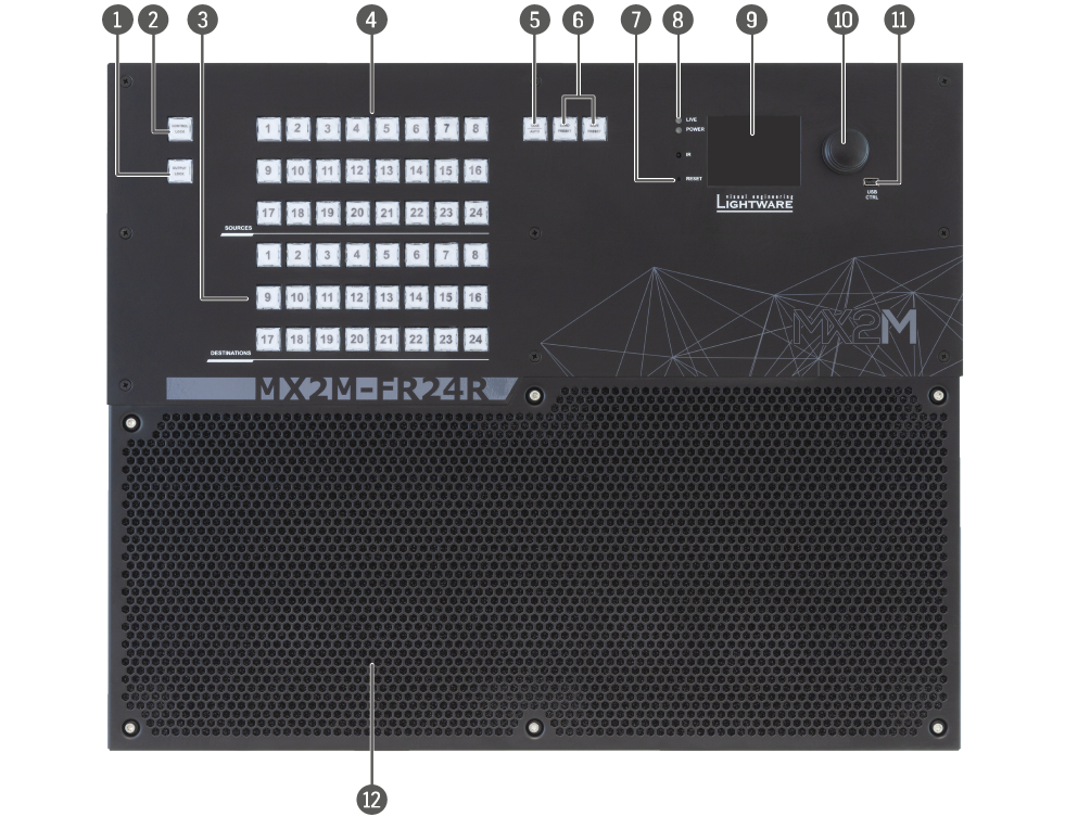
2.1. Matrix Frame - Front View
MX2M-FR24R
|
|
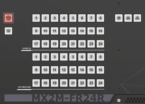
Output lock |
Locks and protects one or more outputs. See more details in the Output Lock section. |
|||
|
|
Control lock |
Disables or enables front panel button operations. Red light means the switching and function buttons are disabled. See more details in the Control Lock section. |
|||
|
|
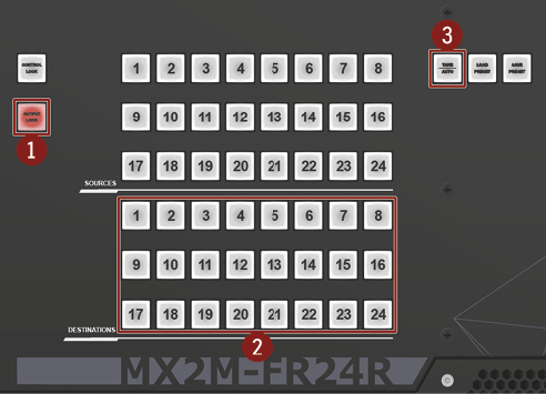
Destinations |
Buttons to select an output or to see the state of an output. See more details in the Switching Operations section. |
|||
|
|
Sources |
Buttons to select an input, to select a preset number or to view the state of the selected input port. See more details in the Switching Operations section. |
|||
|
|
Take / Auto |
Switching between Take and Autotake working modes; keep the button pressed for 3 seconds to toggle the modes. See more details in the Take / Autotake Mode section. |
|||
|
|
Preset buttons |
Performing preset operations (Load and Save). See more details in the Preset Operations section. |
|||
|
|
Reset button |
Reboots the matrix; the same as switching it off and on again. |
|||
|
|
Status LEDs |
The status LEDs give immediate feedback about the matrix. |
|||
|
LIVE |

|
off |
The device is powered off. |
||

|
blinking (green) |
The unit is on and operates properly. |
|||
|
POWER |

|
off |
The unit is powered off or it has internal voltage problem. |
||

|
on (green) |
The device is powered on. |
|||
|
|
LCD screen |
LCD screen showing the most important settings and parameters in the front panel menu. See more details in the Front Panel LCD Menu Operations section. |
|||
|
|
Jog dial control knob |
Easy setting and menu navigation by the jog dial control. See more details in the Front Panel LCD Menu Operations section. |
|||
|
|
USB control |
USB connection for Lightware Device Controller (LDC) software. |
|||
|
|
Ventilation grille and dust filter |
To ensure the correct ventilation and avoid overheating, provide enough free space around the ventilation holes. |
|||


INFO:The rack ears allow to mount the device as a standard rack unit installation and the grips on the two sides of the unit help handling the matrix easier. See more details in the Mounting Options section.
2.2. Matrix Frame - Rear View
MX2M-FR24R

|
|
Auxiliary board slots |
Board slots for the Auxiliary (AUX) Boards. These slots support low-speed boards only. |
|
|
Input board slots |
Board slots for the AV Input (IB) Boards. These slots support high-speed input boards and low-speed boards as well. |
|
|
Output board slots |
Board slots for the AV Output (OB) Boards. These slots support high-speed output boards and low-speed boards as well. |
|
|
Power supply units |
Hot swap slots for Power Drawers. The matrix has redundant power drawers that can be switched on and off without interrupting the video transmission. Using one or both of the power drawers at the same time is also possible. The double power drawer allows connecting them to two different AC power lines to ensure the continuous power for the matrix. |
|
|
Uplink / Secure control connector |
Neutrik etherCON Ethernet connector with 1 Gbps Ethernet connection to control the device, firmware update purpose and for user Ethernet access. |
|
|
Uplink connector |
Neutrik etherCON Ethernet connector with 1 Gbps Ethernet connections for user Ethernet access. |
|
|
Secure control connector |
Neutrik etherCON Ethernet connector with 1 Gbps Ethernet connection to control the device and for firmware update purpose. |
|
|
RS-232 connector |
9-pole D-SUB connector for serial communication to control the device. |
|
|
Service button |
Hidden button for special operations. |

Layout of the Input/Output Board Slots and Power Drawer Slots

The following figure shows the layout of the auxiliary (AUX), input (IB), output (OB) board slots and the order of the power drawers on the rear side of the matrix.
See more details about the installation of the I/O boards in the Board Installation and Handling section.
See more details about the installation of the power supply units in the Power Drawer Installation section.
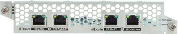
Ports
▪4x RJ45 connectors for Dante® network audio
Features
▪Transmission of 2 x 16 uncompressed mono audio channels from the audio layer to a Dante network
▪Reception of 2 x 16 mono audio channels from a Dante network to the Audio layer
▪Dante and AES67 support
▪Redundant configuration for the Dante network
▪Independent transmission of the same audio content from the Audio layer to two separate Dante networks
▪Hot-swappable design
See more information about the front panel LED operation in the Status LEDs and the Status LEDs of the SC Connectors sections.

Ports
▪8x 5-pole Phoenix® connectors for analog audio input or output
Features
▪Independently configurable audio interface direction with interface direction indicator (see more details about it in the Analog Audio Port Configuration section)
▪ADC conversion of balanced or unbalanced stereo analog audio input to the audio layer
▪DAC conversion of uncompressed audio from the Audio layer to the balanced stereo analog audio output
▪Hot-swappable design
See more information about the front panel LED operation in the Status LEDs and the Analog Audio Input/Output Indicator LEDs sections.

Ports
▪4x HDMI input connectors supporting HDMI 2.0 standard
Features
▪Uncompressed video up to 18 Gbps datarate (600 MHz pixel clock)
▪4K@60Hz 4:4:4, 18 Gbps bandwidth
▪HDMI 2.0 compliant
▪HDCP 1.x and 2.3 support
▪Audio signal passthrough and de-embedding to the Audio layer
▪HDMI input ports have flange mounting option
▪Hot-swappable design
See more information about the front panel LED operation in the Status LEDs section.

Ports
▪4x multimode SC simplex input connectors supporting HDMI 2.0 standard
Features
▪Single Fiber Technology, multimode transmission via SC connector
▪Uncompressed video up to 18 Gbps datarate (600 MHz pixel clock)
▪4K@60Hz 4:4:4, 18 Gbps bandwidth
▪Compatible with HDMI20-OPTJ-TX90 fiber optical extender
▪Audio signal passthrough and de-embedding to the Audio layer
▪Hot-swappable design
See more information about the front panel LED operation in the Status LEDs and the Status LEDs of the SC Connectors sections.

Ports
▪4x RJ45 input connectors for SDVoE point-to-point connection supporting HDMI 2.0 standard
Features
▪4K@60Hz 4:4:4, 18 Gbps bandwidth
▪HDMI 2.0 compliant
▪HDCP 1.x and 2.3 support
▪Compatible with HDMI-TPX-100 and HDMI-TPX-200 series extenders
▪De-embedding audio from the incoming SDVoE streams to the Audio layer
▪Hot-swappable design
See more information about the front panel LED operation in the Status LEDs and the Status LEDs of the TPX Connectors sections.

Ports
▪4x DisplayPort input connectors supporting DisplayPort 1.2 standard
Features
▪DisplayPort 1.2 compliant
▪DisplayPort input signals are converted to HDMI signals via the built-in chipset on each port 1
▪Supported input format of 4K@60Hz with 4:4:4 sampling pattern and 10 bit per component
▪Supports conversion from 4K/UHD at 60Hz 4:4:4 10bit to 4K/UHD at 60 Hz YCbCr 4:2:2 10 bit
▪Audio signal passthrough and de-embedding to the Audio layer
▪The board is a perfect fit for environments that primarily utilize DisplayPort connectivity for video signal transmission, such as laptops and high-end monitors, without the need for any additional adapters or dongles. 2
▪Hot-swappable design
See more information about the front panel LED operation in the Status LEDs section.
1 Input signals that do not fit in the HDMI 2.0 data speeds of 18Gbps can be converted to 4:2:2 while maintaining bit depth, thus allowing for HDR transmission.
2 Ports on the MX2M-DH-4DP12-IB board are recognized by the connected DisplayPort source as DP-to-HDMI converters. Furthermore, it’s important to note that DP Multi-Stream (MST), Dual-mode DisplayPort (DP++), Adaptive-Sync and FreeSync™ are not supported.
INFO:When the DisplayPort source sends RGB 4:4:4 10-bit HDR signal, then it will be converted to 8-bit HDMI signal, if the AV signal exceeds the bandwidth limitation of the HDMI 2.0 standard, else the original content is transmitted. Enabling YCbCr 4:2:2 conversion will save bandwidth by chroma subsampling and preserve the color depth.

Ports
▪4x HDMI output connectors supporting HDMI 2.0 standard
Features
▪Uncompressed video up to 18 Gbps datarate (600 MHz pixel clock)
▪4K@60Hz 4:4:4, 18 Gbps bandwidth
▪HDMI 2.0 compliant
▪HDCP 1.x and 2.3 support
▪Audio signal passthrough and embedding from the Audio layer
▪HDMI output ports have flange mounting option
▪Hot-swappable design
See more information about the front panel LED operation in the Status LEDs section.

Ports
▪4x multimode SC simplex output connectors supporting HDMI 2.0 standard
Features
▪Single Fiber Technology, multimode transmission via SC connector
▪Uncompressed video up to 18 Gbps datarate (600 MHz pixel clock)
▪4K@60Hz 4:4:4, 18 Gbps bandwidth
▪Compatible with HDMI20-OPTJ-RX90 fiber optical extender
▪Audio signal passthrough and embedding from the Audio layer
▪Hot-swappable design
See more information about the front panel LED operation in the Status LEDs and the Status LEDs of the SC Connectors sections.
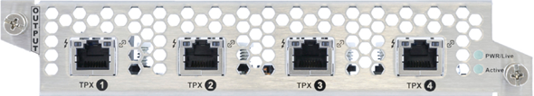
Ports
▪4x RJ45 output connectors for SDVoE AVX connection supporting HDMI 2.0 standard
Features
▪4K@60Hz 4:4:4, 18 Gbps bandwidth
▪HDMI 2.0 compliant
▪HDCP 1.x and 2.3 support
▪Compatible with HDMI-TPX-100 and HDMI-TPX-209 series extenders
▪Audio signal passthrough and embedding from the Audio layer
▪Hot-swappable design
See more information about the front panel LED operation in the Status LEDs and the Status LEDs of the TPX Connectors sections.

Features
▪500 W power output
▪Built-in power button
▪One PSU drawer is able to supply the power requirement of 16 pcs I/O boards
▪Hot-swappable design

Features
▪1250 W power output
▪Built-in power button
▪One PSU drawer is able to supply the power requirement of 16 pcs I/O boards
▪Provides local power for the matrix frame, for the IO boards as well as for remote powering (PoE) of PD devices connected to the various IO boards
▪Hot-swappable design
2.7. Front Panel LEDs of the Boards
Affected auxiliary and I/O boards:
|
PWR/Live |
||

|
off |
The board is not powered. |

|
lit at 50% brightness |
The board is under booting procedure. |

|
blinking fast between 0% and 100% brightness |
The board is fitted in an inappropriate slot (input in an output, output in an input slot). Hence, it is not passing video. |

|
blinking between 50% and 100% brightness |
The board is operational (the embedded software is running on the controller). |
|
Active |
||
|
|
off |
The control sequence has not been completed. |

|
on |
The control sequence has been completed and the device is being controlled by the matrix switcher. |

|
blinking (slow) |
The device firmware is under firmware update procedure (bootload mode). |

|
blinking (fast) |
The board is fitted in an inappropriate slot (input in an output, output in an input slot). Hence, it is not passing video. |
2.7.2. Status LEDs of the SC Connectors
Affected I/O boards:
|
OPTJ 1 / OPTJ 2 / OPTJ 3 / OPTJ 4 |
||
|
|
off |
The optical RX module is not powered. |

|
blinking (red) |
No fiber is connected and the laser is disabled. |

|
on (yellow) |
Fiber detected but link initialization failed. |
|
|
blinking (green) |
Link is receiving video without HDCP encryption. |

|
on (green) |
Link is receiving video with HDCP 1.x encryption. |

|
on (blue) |
Link is receiving video with HDCP 2.x encryption. |

|
on (pink) |
The optical RX module is in bootload (firmware update) mode. |

|
blinking (pink) |
|
2.7.3. Dante Connector LEDs
Affected auxiliary board:
|
LED1 (left side) |
amber |

|
off |
not linked |

|
on |
no activity |
|||

|
blinking |
activity |
|||
|
LED2 (right side) |
green |
|
off |
0 Mbit/s |
|

|
on |
1000 Mbit/s |
2.7.4. Analog Audio Input/Output Indicator LEDs
Affected auxiliary board:
|
Input / Output indicator |
||

|
off |
The port is configured as analog audio input. |

|
on |
The port is configured as analog audio output. |
2.7.5. Status LEDs of the TPX Connectors
Affected auxiliary board:

|
LED1 (left side) |
amber / green |

|
off |
No connection is established between the board and the receiver unit. |

|
on |
Connection is established with 10G / 5G / 2.5G bandwith. |
|||

|
blinking |
Link training is in progress. |
|||
|
LED2 (right side) |
green |

|
off |
No data transmission on the port. |
|

|
on |
Data transmission is active. |
This chapter is about the operating of operating the device, describing the functions that are available by the front panel controls:
3.1. Front Panel Button Operations
The following section describes the crosspoint switching possibilities using the dedicated buttons on front panel of the matrix frame.
The matrix switcher has two different switching modes: Take and Autotake. If the Take button is unlit, Take mode is active. When the Take button continuously illuminates green, Autotake mode is selected.
Press and hold the Take button for two seconds to change between Take and Autotake modes. #button #crosspoint #switch #takemode #autotakemode
Take Mode

DEFINITION:The Take mode allows the user to connect or disconnect multiple outputs to an input at once, but the layout must be confirmed (executed) by the Take button as a final step.
The commands are only realized when the Take button is pressed. If no button is pressed for two seconds, all preselected actions (which were not realized by pressing Take) will be ignored, and the router returns to its idle state. This mode is useful when time delay is not allowed between multiple switching.
Autotake Mode

DEFINITION:The Autotake mode means the switching actions are executed immediately (without user confirmation).
The switching occurs immediately upon pressing one of the input selector buttons. Autotake mode is useful when immediate actions must be done or fast switching is needed between sources on a particular destination. In this mode switching occurs immediately upon pressing one of the input selector buttons.

The current switching status can be checked on the front panel by using the front panel buttons. The crosspoint state is displayed slightly different in Take or Autotake modes because of the different switching methods.
INFO:View mode does not mean that the router has to be switched in different modes, viewing and switching can be done after each other, without pressing any special buttons.
View Current State in Take Mode
If the router is in Take mode, the user can verify both input and output connections. In Take mode no accidental change can be done unless Take button is pressed.
Press and release a source button. Now the selected source button and all destination buttons that are currently connected to the selected source will light up. This informative display will remain active for three seconds, then all buttons turn dark.
View Current State in Autotake Mode

In Autotake mode only the states of the destinations can be viewed.
Press and release the required destination button. Now the source button that is connected to the selected destination will light up. If no source button is lighting, the selected destination is muted or disconnected. By pressing another destination button, the state of that destination can be seen.
ATTENTION!Be careful, as if a source button is pressed in AUTOTAKE mode, it is immediately connected to the last selected destination.
INFO:Muting or disconnecting an output cannot be done in Autotake mode.
Changing Connections in Take Mode

Step 1.Press and release the desired source button. The pressed source button and all destination buttons that are currently connected to this source will light up. This is an informative display about the current status of the selected input (view only).
Step 2.Press and release the desired destination button(s) that has to be connected to the selected source. The preselected destination button(s) start(s) blinking.
Step 3.Press and release the Take button to execute switching. Now the selected input is switched to the selected output or to the multiple outputs.
ATTENTION!A source button can be pressed twice to preselect all outputs. Outputs that are connected to the pressed input light up and all other outputs start to blink. Some outputs can be unselected if needed, and then pressing Take executes the switching.
INFO:If the pressed destination is locked, then it can not be selected. This is indicated by a short flash of the Output lock when a locked destination is pressed.
#crosspoint #switch #takemode
Disconnecting or Muting in Take Mode

Step 1.Press and release the selected source button. The pressed source button and all destination buttons that are currently connected to this source will light up.
Step 2.Press and release the desired green lighting destination button. The pressed destination or multiple destinations will turn dark.
Step 3.Press and release the Take button to execute disconnection.
INFO:Deselected destinations are disconnected from any source, thus output devices will display black image or no signal message, or will turn off automatically.
Changing Connections in Autotake Mode

Step 1.Press and release the desired destination button. The pressed destination button and the currently connected source button light up green. If no source is connected (the output is muted), no source button will light up.
Step 2.Press and release the desired source button. Switching is executed immediately. Switching between sources to the selected destination can be done directly.
Disconnecting or Muting in AUTOTAKE Mode
To prevent accidental muting, this action is inhibited (disabled) in Autotake mode. Pressing a source button twice would cause accidental disconnecting.
#crosspoint #switch #autotakemode
DEFINITION:A preset stores a configuration regarding all input connections and mute state for all outputs.
INFO:The matrix switcher has 24 user programmable presets. All presets are stored in a non-volatile memory; the router keeps presets even in the case of a power down. Memory numbers are assigned to source buttons 1 to 24. If the frame has fewer buttons, the higher numbered presets are accessible only through software control.
Saving a Preset in Take Mode #preset

Create the desired connections that have to be saved.
Step 1.Press and release the Save preset button.
Step 2.Press and release a source button according to the desired memory address (source 1 to 24).
Step 3.Press and release the Take button. Now the current configuration is stored in the selected memory.
ATTENTION!Preset save action always stores the current configuration for all outputs including mute state, but ignoring lock state.
Loading a Preset in Take Mode

Step 1.Press and release the Load Preset button.
Step 2.Press and release a source button according to the desired memory address (source 1 to 24).
Step 3.Press and release the Take button. Now the selected preset is loaded.
ATTENTION!Loading a preset modifies all output states that are not currently locked.
Saving a Preset in Autotake Mode

Create the desired connections that have to be saved.
Step 1.Press and release Save Preset button.
Step 2.Press and release a source button according to the desired memory address (source 1 to 24). Now the current configuration is stored in the selected memory.
ATTENTION!Preset save action always stores the current configuration for all outputs including mute state, but lock state is ignored.
Loading a Preset in Autotake Mode

Step 1.Press and release Load Preset button.
Step 2.Press and release a source button according to the desired memory address (source 1 to 24). Now the selected preset is loaded.
ATTENTION!Loading a preset modifies all output states that are not currently locked.

DEFINITION:The Output lock means that an input port is locked to an output port, and no input change or muting can be executed on that particular output port.
Using Lightware matrix it is possible to lock a state of the destination. This feature prevents an accidental switching to the locked destination in the case of an important signal. Destinations can be independently locked or unlocked. Locking a destination does not affect other destinations. #lock #unlock #outputlock
View Locked Outputs in Take Mode

Step 1.Press and release the Output Lock button.
Step 2.The Output Lock button starts to blink and all the buttons of any locked destinations light up and remain illuminated for three seconds.
Locking an Output in Take Mode
Step 1.Press and release the Output Lock button. Now the Output Lock button starts to blink and the buttons of all the locked outputs illuminate green (view state). If no button is pressed for three seconds, the router returns to idle state.
Step 2.Press the desired destination buttons. If an unlit destination button is pressed, it starts to blink, indicating that it is preselected for output locking.
Step 3.Press and release the Take button. The selected destinations are now locked.
Unlocking an Output in Take Mode
Step 1.Press and release the Output Lock button. Now the Output Lock button starts to blink and all the locked output’s buttons illuminate green (view state). If no button is pressed for three seconds, the router returns to idle state.
Step 2.If an illuminating destination button is pressed, it goes off to indicate that it is preselected for unlocking.
Step 3.Press and release the Take button. The deselected destinations are now unlocked.
View Locked Outputs in Autotake Mode
In Autotake mode a destination is selected all the time. Therefore the currently selected output and input buttons are illuminated. The Output Lock button illuminates regarding the lock state of the current output.
Viewing all locked outputs is not possible is Autotake mode, as pressing the Output Lock button instantly locks or unlocks the current output.
Locking an Output in Autotake Mode


Step 1.Press and release the required destination button. Now the selected destination button and the currently configured source button light up (view mode).
Step 2.Press and release the Output Lock button. Now the Output Lock button lights up in red, and lock function is activated at once. No source can be changed at the locked destination.
Unlocking an Output in Autotake Mode
Step 1.Press and release the required destination button that was previously locked. Now the selected destination button, the currently configured source button and the Output Lock button light up.
Step 2.Press and release the Output Lock button (deselection). Now the Output Lock button turns off and the port has been unlocked.


DEFINITION:The Control Lock means to disable the front panel buttons.
While the front panel buttons are disabled, the RS-232, USB and Ethernet control are still enabled. If the button is not illuminated, front panel button operations are enabled. If it illuminates red continuously, front panel operations are inhibited (including LCD menu).
Press and hold the Control lock button for 3 seconds to toggle the control lock state. #button #controllock
3.2. Front Panel LCD Menu Operations
3.2.1. Introduction
The company logo is displayed on the screen during the boot-up. The main menu is displayed after about 30 seconds and the device is ready for use.
Menu Navigation

The front panel has a color LCD that shows the most important settings and parameters structured in a menu. The jog dial control knob can be used to navigate between the menu items or change the value of a parameter. The knob can be pressed to enter a menu or edit/set a parameter.
TIPS AND TRICKS:The faster you rotate the jog dial, the faster the parameter list is scrolled.
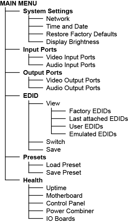
The Menu Structure

Parameter Selection
The blue colored line means the selected menu/parameter, the green one means the current setting.
Enter the Menu / Submenu
The  icon before the line indicates the additional submenus. Click with the rotary to enter.
The  icon shows that there is no submenu or setting possibility.
Network

The parameters of the network connection can be set in this submenu. The first three lines (IP, Subnet, and Gateway parameters) show the current settings. If the DHCP option is disabled, three more parameters are listed, which can be set for a static IP address: #network #ipaddress #dhcp
▪Static IP,
▪Static subnet,
▪Static gateway.
ATTENTION!If you change the network settings, always press the Save option under Network menu (not only in the submenu of the parameter) to apply the new settings.
Time and Date

The internal clock and date that is used for logging events can be set in this submenu. #time #date
Restore Factory Defaults
The default settings can be reloaded in this submenu, for details, see the Factory Default Settings section. #factory
Display Brightness

The brightness of the LCD can be set from 1 to 10 on a scale.
3.2.3. Input Ports Menu
Video Input Ports
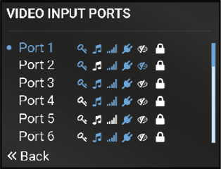
The most important status information of the video input ports are available in the menu.
INFO:The number of the video input ports depends on the installed IB boards in the matrix switcher.
Legend of the Icons
The icons display information about the port and the incoming signals.
|
Icon |
Icon is white (inactive) |
Icon is blue (active) |
|
|
Signal is not encrypted with HDCP |
Signal is encrypted with HDCP |
|
|
No audio signal in the video stream |
Audio is embedded in the video stream |
|
|
Signal is not present |
Signal is present |
|
|
Source is not connected |
Source is connected |
|
|
Port is unmuted |
Port is muted |
|
|
Port is unlocked |
Port is locked |


Audio Input Ports
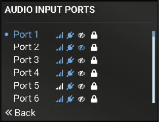
The most important status information of the audio input ports is available in the menu.
INFO:The number of the audio input ports depends on the installed auxiliary and IB boards in the matrix switcher.
Legend of the Icons
The icons display information about the audio port and the incoming signals.
|
Icon |
Icon is white (inactive) |
Icon is blue (active) |
|
|
Signal is not present |
Signal is present |
|
|
Source is not connected |
Source is connected |
|
|
Port is unmuted |
Port is muted |
|
|
Port is unlocked |
Port is locked |
3.2.4. Output Ports Menu
Video Output Ports

The most important status information of the video output ports are available in the menu.
INFO:The number of the video output ports depends on the installed OB boards in the matrix switcher.
Legend of the Icons
The icons display information about the port and the transmitted signals.
|
Icon |
Icon is white (inactive) |
Icon is blue (active) |
|
|
Signal is not encrypted with HDCP |
Signal is encrypted with HDCP |
|
|
No audio signal in the video stream |
Audio is embedded in the video stream |
|
|
Signal is not present |
Signal is present |
|
|
Sink is not connected |
Sink is connected |
|
|
Port is unmuted |
Port is muted |
|
|
Port is unlocked |
Port is locked |
Audio Output Ports

The most important status information of the audio output ports is available in the menu.
INFO:The number of the audio output ports depends on the installed auxiliary and OB boards in the matrix switcher.
Legend of the Icons
The icons display information about the port and the transmitted signals.
|
Icon |
Icon is white (inactive) |
Icon is blue (active) |
|
|
Signal is not present |
Signal is present |
|
|
Sink is not connected |
Sink is connected |
|
|
Port is unmuted |
Port is muted |
|
|
Port is unlocked |
Port is locked |
Advanced EDID Management is available in the front panel LCD menu, which allows to view an EDID, switch, or save it to the User EDID memory. See more information about EDID technology in EDID Management section. The EDID memory structure of the device can be found in Advanced EDID Management section. #edid
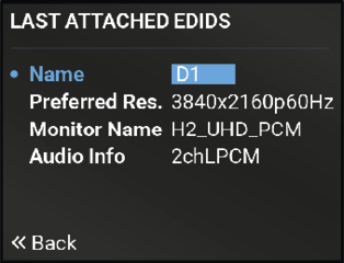
Select the desired EDID memory block: Factory EDIDs, Last attached EDIDs, User EDIDs, or Emulated EDIDs. Select the Name item and press the knob. Use the jog dial to step between the EDIDs. The following information can be checked:
▪Preferred Resolution
▪Monitor Name
▪Audio Info

The submenu looks similar as the View submenu, but in this case, the Destination is also listed. To change an EDID, do the following steps:
Step 1.Navigate to the EDID / Switch submenu.
Step 2.Select the Source EDID item and press the knob. Use the jog dial to select the desired EDID (F1-F148, U1-U100, or D1-D24) and press the knob.
Step 3.Select the Destination item and press the knob. Use the jog dial to select the desired EDID memory (E1-E2, All) and press the knob.
Step 4.Navigate to the Switch option and press the knob.

The EDID of a connected sink can be saved to the User EDID memory as follows:
Step 1.Navigate to the EDID / Save submenu.
Step 2.Select the Source EDID item and press the knob. Use the jog dial to select the desired EDID (D1-D4) and press the knob.
Step 3.Select the Destination item and press the knob. Use the jog dial to select the desired EDID memory (U1-U12) and press the knob.
Step 4.Navigate to the Save option and press the knob.
3.2.6. Preset Menu
The router can store presets and the following are stored in each slot: Input/output crosspoint state, muted/unmuted states. #preset
ATTENTION!When factory default settings are restored, presets are deleted.
Load a Preset
ATTENTION!The Preset loading has an effect on all ports, except the locked ones.
Step 1.Navigate to the Presets / Load Preset submenu and press the knob.
Step 2.The previously save presets are listed. Select the desired memory slot and press the knob. If any other preset had been saved previously, they would be also listed.
Step 3.Confirm your selection by pressing Yes.
Save a Preset
Step 1.Create the desired I/O layout.
Step 2.Navigate to the Presets / Save Preset submenu and press the knob.
Step 3.Select the desired memory slot and press the knob. If any other preset had been saved previously, they would be also listed. See the corresponding Presets section in the Lightware Device Controller (LDC) software.
Step 4.Confirm your selection by pressing Yes.
3.2.7. Health Menu

Health status overview of the matrix switcher and the most important information about the motherboard, control panel, power combiner and the I/O boards of the device.
Uptime
The time passed since the last powering up of the device.
Motherboard
Temperatures and fan speed status information are listed in the submenu.
Control Panel
The temperature of the control panel can be checked in the submenu.
Power Combiner
Fan speed, temperature and voltage status information about the Power Combiner 1 and 2 slots.
IO Boards
Temperature and voltage status information about the input (IB), output (OB) and auxiliary (AUX) boards.
Legend
|
Status |
Color |
Description |
|
ok |
green |
No active warning or error level log entry exists for the system or a device seated in the system. |
|
warning |
yellow |
Active warning level log entry exists and no active error level log entry exists for the system or a device seated in the system. |
|
error |
red |
Active error level log entry exists for the system or a device seated in the system. |
The chapter is about the installation of the device and connecting to other appliances, presenting also the mounting options and further assembly steps.
WARNING!For the correct ventilation and to avoid overheating, ensure enough free space around the appliance. Do not cover the appliance, leave the ventilation holes free and never block or bypass the fans.
INFO:The dimensions of the frame can be found in the Mechanical Drawings section.
Fixing the Handles
Two handles can be mounted on the rack ears of the matrix switcher. The handles are supplied with the product.
Fasten the 2x 2 pcs M5 flat head fixing screws to fix the handles to the rack ears.

Fixing the handles to the rack ears of the matrix
Standard Rack Installation
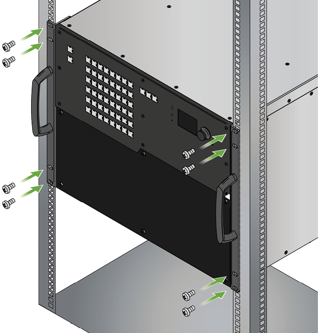
Two rack ears are supplied with the product, which are fixed on left and right side as shown in the picture. The default position allows mounting the device as a standard rack unit installation.
Standard rack cabinet installation

ATTENTION!Always use all the four screws for fixing the rack shelf ears to the rack rail. Choose properly sized screws for mounting. Keep a minimum of two threads left after the nut screw.
4.2. Board Installation and Handling
The I/O boards and the PSU drawers are hot-swappable. The matrix is not required to be powered off before removing / inserting a board.
4.2.1. The Layout of the Input/Output Board Slots
The following figure shows the layout and the numbering of the auxiliary (AUX, highlighted in yellow), input (IB, highlighted in purple) and output (OB, highlighted in green) board slots on the rear side of the matrix.
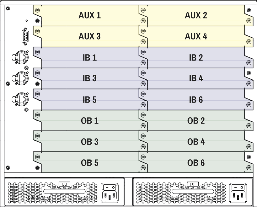
The layout of the I/O board slots
Auxiliary (AUX) Board Slots
The first four board slots are dedicated for the auxiliary (AUX) boards, which are also known as low-speed boards. These slots are able to accept AUX boards only.
The list of AUX boards:
Input (IB) Board Slots
The next six board slots are dedicated for the input (IB) boards, which are also known as high-speed boards. These slots are able to accept IB (high-speed) boards and AUX (low-speed) boards as well.
The list of the IB boards:
Output (OB) Board Slots
The last six board slots are dedicated for the output (OB) boards, which are also known as high-speed boards. These slots are able to accept OB (high-speed) boards and AUX (low-speed) boards as well.
The list of the OB boards:
4.2.2. Installation of an I/O Board

WARNING!Please pay attention to the protection against electrostatic discharge when touching a board. Do not touch the electrical components on the board, as the electrostatic discharge may damage them.
ATTENTION!Please check the orientation of the slots. The AUX, IB and OB boards are assigned to dedicated board slots in the matrix.
INFO:The MX2M series I/O boards are hot-swappable devices. The matrix switcher is not required to be powered off before the board replacement procedure.
The steps of replacing an auxiliary, input or output board are the following:
Step 1.Loosen the fixing screws and remove the blank cover or the previously installed board.
Step 2.Pull out the board and put it in an ESD-safe bag. Take the board by touching the metal plate only, to prevent ESD-caused problems.
Step 3.Place the board into the desired empty slot. Place the edge of the panel carefully to the guide rails on the two sides of the slot. Gently push the board in until it stops, then press the plate at the indicated places at once. Thus, the connector of the board and the motherboard will be put together.

Step 4.Tighten the two screws by hand and fix them by a screwdriver with PZ1 head.
Step 5.Connect the necessary cables to the boards and switch on the matrix.
Step 6.Wait until the booting procedure of the board is completed.
INFO:If the firmware version of the installed I/O board is different than the firmware version of the matrix frame, it is being updated by the matrix automatically.
4.3. Power Drawer Installation
Two dedicated power drawer slots are available in the matrix frame for the MX2M-PSU-500-F and MX2M-PSU-1250-FP power supply units. The power drawer of the frame is hot-swappable, thus you do not have to switch off the matrix to replace or install a power drawer.
The Steps of the Power Drawer Replacement
Step 1.Push down the fixing plate on the power drawer.

Step 2.Pull out the power drawer using the handle.

Step 3.Place the new power drawer to the power drawer slot and push it using the handle until the device connects to the motherboard of the frame.
ATTENTION!Make sure that the fixing plate is correctly in its place.

The following sections describe all possible electrical connections of the MX2M series frames, power drawers and I/O boards.

MX2M-PSU-500-F and MX2M-PSU-1250-FP power drawers contain standard IEC power connector and work with 100 to 240 Volts AC, 50 Hz or 60 Hz power sources.
|
Power drawer |
Type |
Number of power drawer slots in the frame |
Output per power drawer (max) |
|
MX2M-PSU-500-F |
hot-swappable |
2 |
500 W |
|
MX2M-PSU-1250-FP |
hot-swappable |
2 |
1250 W |
See the details about the powering on procedure in the Powering On section.
4.4.2. USB Mini-B Connector

MX2M series matrix frame provides standard USB 2.0 mini B-type connector for software control and firmware update purpose.
4.4.3. Ethernet Connectors
Neutrik etherCON Connectors

MX2M series matrix frame provides Neutrik etherCON RJ45 connectors for secure control purpose, LAN and user Ethernet access.
Standard RJ45 Connector
MX2M-AUX-DANTE-32CH and MX2M-4TPX series I/O boards provide standard RJ45 connectors. Always use high quality Ethernet cable.
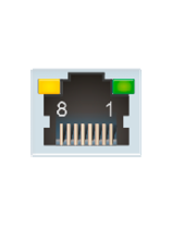
Wiring of LAN Cables
Lightware recommends the termination of LAN cables on the basis of TIA/EIA T 568 A or TIA/EIA T 568 B standards.

Wiring of LAN cables by types
WARNING!Never connect a non-assembled CATx cable to the port while the unit is powered, it may damage the device.
4.4.4. RS-232 Connector

The matrix frame has a standard 9 pin D-sub female (DE9F) miniature receptacle for device control purpose.
|
Pin nr. |
RS-232 straight pin-out |
RS-232 cross pin-out |
|
1 |
Not connected |
Not connected |
|
2 |
TX data transmit (out) |
RX data receive (in) |
|
3 |
RX data receive (in) |
TX data transmit (out) |
|
4 |
DTR (Internally connected to Pin 6) |
DTR (Internally connected to Pin 6) |
|
5 |
GND signal ground (shield) |
GND signal ground (shield) |
|
6 |
DSR (Internally connected to Pin 4) |
DSR (Internally connected to Pin 4) |
|
7 |
RTS (Internally connected to Pin 8) |
RTS (Internally connected to Pin 8) |
|
8 |
CTS (Internally connected to Pin 7) |
CTS (Internally connected to Pin 7) |
|
9 |
Not connected |
Not connected |
Wiring methods of the DE9F D-sub connector
4.4.5. Symmetrical Analog Stereo Audio Connector
MX2M-AUX-8AUDIO auxiliary board provides 5-pole Phoenix connectors, which are used for balanced analog audio (line in/out). Unbalanced audio signals can be connected as well. For asymmetrical output, connect only + and ground. For asymmetrical input, connect + and ground to the source and connect – to the ground.
Compatible Plug Type
Phoenix® Combicon series (3.5mm pitch), type: MC 1.5/5-ST-3.5.

5-pole Phoenix connector pin assignments
See more information about the most common audio cable wiring modes in Cable Wiring Guide section.
You can find more information about audio embedding and de-embedding functions in the Audio Layer section.
4.4.6. HDMI Connector

MX2M-4HDMI20 series I/O boards provide standard 19-pole HDMI connectors for inputs and outputs with HDMI 2.0 support. Always use high quality HDMI cables for connecting sources and displays.
INFO:HDMI input and output connectors have flange mounting option.
You can find more information about the video related functions in the Video Layer section.
4.4.7. DisplayPort Connector

MX2M-DH-4DP12-IB input board provides standard 20-pole DisplayPort connectors for inputs with DisplayPort 1.2 support. Always use high quality DP cables for connecting sources and displays.
You can find more information about the video related functions in the Video Layer section.
4.4.8. SC Fiber Optical Connector

MX2M-4OPTJ series I/O boards provide multimode SC simplex fiber optical input and output connectors. The connectors are compatible with the HDMI20-OPTJ-90 series fiber optical extenders.
You can find more information about the video related functions in the Video Layer section.
Maximum cable distances can be found in the Maximum Cable Distances section.
4.5. Analog Audio Port Configuration
The analog audio ports of the MX2M-AUX-8AUDIO board can be configured as input and output by the user. The port configuration can be done by placing a jumper to the right pins.
WARNING!Always apply ESD-protection during the port configuration. Electric discharge may harm the electric parts of the board.
Steps of the Configuration
Step 1.Release the two fixing screws of the board and pull it out.
Step 2.Find the 3-pole port configuration pin set behind the 5-pole Phoenix connector.
Step 3.Place the jumper to re-configure the port as follows:

|

|
|
The port is configured as an input |
The port is configured as an output |
Step 4.Place the board into the desired slot.
Step 5.Tighten the two screws by hand and fix them by a screwdriver with PZ1 head.
Step 6.Connect the necessary cables to the boards and switch on the matrix.
Step 7.Wait until the booting procedure of the board is completed.
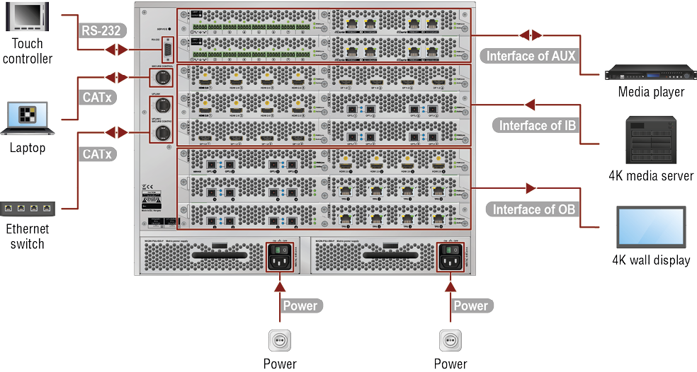
|
|
Optionally for RS-232 control: connect a controller device (e.g. touch panel) to the RS-232 port. |
|
|
Connect the matrix switcher to a controller device (e.g. laptop) via the Secure Control port over a CATx cable. The port supports 1 GbE data transmission. |
|
|
Connect the matrix switcher to a LAN via the Uplink and Uplink / Secure Control ports over CATx cables. The Uplink port is for user Ethernet access; the Uplink / Secure control port is for user Ethernet access or control the matrix switcher. Both ports support 1 GbE data transmission. |
|
|
Connect the power cords to the AC power sockets and to the matrix. If the matrix is purchased with only one power drawer, connect the power cord to the AC power socket and to the matrix. See more details about it in the Single PSU License section. The matrix has redundant PSU drawers, which can be switched on and off without interrupting the video transmission. Using one or both of the PSU drawers at the same time is also possible. The double power drawer allows connecting them to two different AC power lines to ensure the continuous power for the matrix. See more details about the powering on procedure in the Powering On section. |
|
|
Connect the source / sink devices (e.g. media player) to the ports of the MX2M-AUX series boards via the interface of the board. See the connection possibilities grouped by I/O board variants: ▪MX2M-AUX-8AUDIO - Connect audio source devices to the audio input connectors and audio sink devices to the audio output connectors. The input/output function of the ports can be modified anytime by the user, see the details in the Analog Audio Port Configuration section. See the wiring guide for the Phoenix 5-pole connector in the Cable Wiring Guide section. ▪MX2M-AUX-DANTE-32CH - Connect the Dante® or AES67 audio source and sink devices to the Primary connectors and the redundant connections to the Secondary connectors via Ethernet cables. The recommended cable type for 1 GbE signal transmission is CAT5e or CAT7e up to 100 m. |
|
|
Connect the AV source devices (e.g. 4K media server) to the ports of the MX2M-IB series boards via the interface of the board (DisplayPort, HDMI, fiber optical, etc). See the connection possibilities grouped by I/O board variants: ▪MX2M-4HDMI20-IB - Connect the source devices using the HDMI 2.0 ports by HDMI cables. ▪MX2M-DH-4DP12-IB - Connect the source devices using the DP 1.2 ports by DisplayPort cables. ▪MX2M-4OPTJ-IB - Connect a single multimode fiber optical cable between the OPTJ SC connectors and the HDMI20-OPTJ-TX90 extenders. See the details about the maximum fiber cable extensions in the Maximum Cable Distances section. ▪MX2M-4TPX-IB - Connect a CATx cable between the TPX RJ45 connectors and the HDMI-TPX series transmitter. See the details about the maximum CATx cable extensions in the Maximum Cable Distances section. |
|
|
Connect the AV sink devices to the ports (e.g. 4K wall display) of the MX2M-OB series boards via the interface of the board (HDMI, fiber optical, etc). See the connection possibilities grouped by I/O board variants: ▪MX2M-4HDMI20-OB - Connect the sink devices using the HDMI 2.0 ports by HDMI cables. ▪MX2M-4OPTJ-OB - Connect a single multimode fiber optical cable between the OPTJ SC connectors and the HDMI20-OPTJ-RX90 extenders. See the details about the maximum fiber cable extensions in the Maximum Cable Distances section. ▪MX2M-4TPX-OB - Connect a CATx cable between the TPX RJ45 connectors and the HDMI-TPX series receiver. See the details about the maximum CATx cable extensions in the Maximum Cable Distances section. |
Connect the power cords to AC input of the power drawers (MX2M-PSU-500-F / MX2M-PSU-1250-FP).
INFO:The router has an internal emergency memory that stores all current settings and tie configurations. This memory is independent from presets and invisible to the user. This built-in feature helps the system to be ready immediately in case of power failure or accidental power down.
Powering On Procedure
After switching the power switch to the ON position, the router starts up. If the switch is in the ON position, then the matrix starts up immediately when the power cord is connected to the AC source. During the initial self-test and loading of the latest settings, The matrix is about to start appears on the LCD screen and the router reloads its last configuration.
INFO:After switching ON, the router reloads the latest settings that were used before it was switched off. The router has an internal emergency memory that stores all current settings and tie configurations.
Redundant Power Supplies
The matrix has redundant power drawers which can be switched on and off without interrupting the video transmission. Using one or both of the power drawers at the same time is also possible.
The double power drawer allows connecting them to two different AC power lines to ensure the continuous power for the matrix. The power drawers are hot-swappable.
5. Hybrid Modular Matrix Concept
The following chapter describes the features of the MX2M series frame and I/O boards with few real-life examples. The topics that are described:
5.1.1. Port Diagram
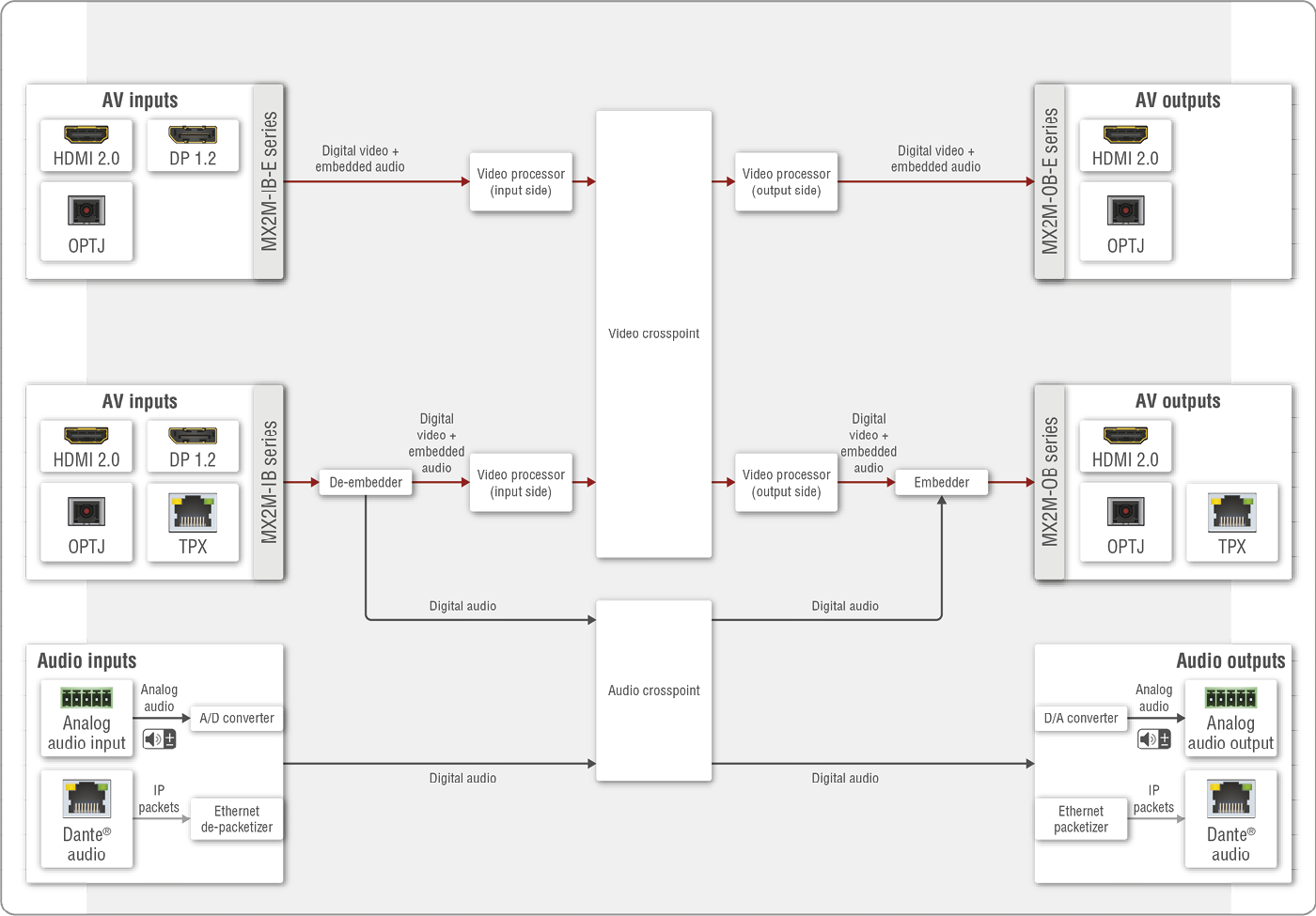
AV port diagram of the MX2M series matrix switcher
INFO:The available audio and video interfaces depend on the installed I/O boards.
Description
The MX2M matrix receives video streams with the embedded audio signal via various types of multimedia ports, which depend on the installed I/O boards. The video streams can be switched to any destination port in the video crosspoint sized up to 24x24.
The video and audio layers are independent of each other. The audio signal is copied to the Audio layer from the stream and routed to the audio crosspoint, where it can be switched to the AV outputs (HDMI, fiber optical or TPX) and the audio outputs (analog audio or Dante network) as well.
Audio input signals can be received via the analog audio input and Dante audio network. The audio streams can be switched to the audio outputs (analog audio or Dante network) or can be embedded into the output streams (HDMI, fiber optical or TPX).
See more details about the audio layer and the available options in the Audio Layer section.
There are video processors on the input and output sides as well. Available functions are the following, grouped by AV interfaces:
▪HDMI 2.0
=Input side: no video processing can be applied.
=Output side: the sampling pattern can be converted from 4:4:4 to 4:2:2.
ATTENTION!The MX2M-4HDMI20-OB output board accepts video signals in 8, 10 and 12 bit color depth, but the sampling pattern conversion is always made in 8 bit.
▪DP 1.2
=Input side: the sampling pattern can be converted from 4:4:4 to 4:2:2 or 4:2:0 and the color depth can be converted 12 bit to 8 bit per channel if the signal bandwidth is greater than 18 Gbit/s.
▪OPTJ
=Input side: no video processing can be applied.
=Output side: the sampling pattern can be converted from 4:4:4 to 4:2:2.
▪TPX
=Input side: no video processing can be applied.
=Output side: the sampling pattern can be converted from 4:4:4 to 4:2:2.
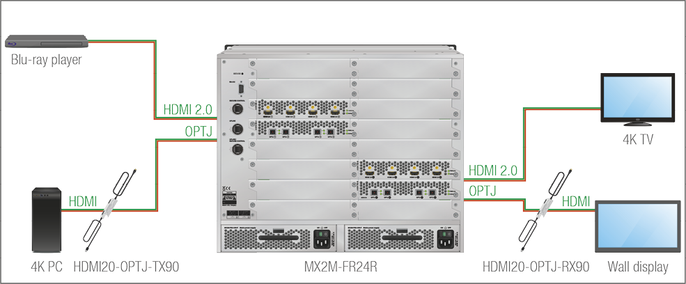
5.1.2. Video Signal Transmission - Example

The Concept
The matrix frame is installed with seven different type of I/O boards:
|
I/O board |
Connection interface |
Signal direction |
Connected device |
|
|
IB |
MX2M-4TPX-IB |
TPX (SDVoE) |
Input |
Barebone PC |
|
MX2M-4HDMI20-IB |
HDMI |
Input |
Blu-ray player |
|
|
MX2M-DH-4DP12-IB |
DisplayPort |
Input |
MacBook |
|
|
MX2M-4OPTJ-IB |
Multimode fiber optical |
Input |
4K PC over a HDMI20-OPTJ-TX90 fiber optical transmitter |
|
|
OB |
MX2M-4OPTJ-OB |
Multimode fiber optical |
Output |
Wall display over a HDMI20-OPTJ-RX90 fiber optical receiver |
|
MX2M-4HDMI20-OB |
HDMI |
Output |
4K TV |
|
|
MX2M-4TPX-OB |
TPX (SDVoE) |
Output |
4K projector over a HDMI-TPX series receiver |
|
The video signals of the input boards can be routed to any port of the output boards. The video crosspoint settings can be set using four different methods:
▪Front panel buttons - see the details in the Switching Operations section;
▪Built-in website / Lightware Device Controller (LDC) software - see the details in the Crosspoint Menu section;
▪LW3 protocol commands - see the details in the Video Switching and Crosspoint Settings section.
Available Video Related Settings
The following settings and options are available for the video stream input:
MX2M--4HDMI20-IB and MX2M--4OPTJ-IB boards:
▪Input port HDCP capability setting
MX2M-DH-4DP12-IB board:
▪Sampling pattern conversion to 4:2:2 or 4:2:0
▪Color depth conversion to 8 bit per channel
▪Input port HDCP capability setting
INFO:When the DisplayPort source sends RGB 4:4:4 10-bit HDR signal, then it will be converted to 8-bit HDMI signal, if the AV signal exceeds the bandwidth limitation of the HDMI 2.0 standard, else the original content is transmitted. Enabling YCbCr 4:2:2 conversion will save bandwidth by chroma subsampling and preserve the color depth.
The following settings and options are available for the video stream output:
▪Sampling pattern conversion to 4:2:2
▪Output port HDCP mode setting
▪Audio stream embedding setting
5.2.1. Overview
The embedded digital audio of the input video stream is copied to the Audio layer and it can be selected to the analog audio interface as well.
On the output side the audio signal can be selected for the output video stream: the original embedded audio is transmitted together with the video or it is changed to another audio (even analog audio) signal that can be selected in the audio crosspoint table.
5.2.2. Digital Audio Interface
Inputs
The matrix is able to receive embedded audio streams via the digital video interfaces:
▪Embedded HDMI audio over the MX2M-4HDMI20-IB / MX2M-4OPTJ-IB / MX2M-4TPX/IB boards;
▪Embedded DisplayPort audio over the MX2M-DH-4DP12-IB board.
INFO:The audio signal can be one that the HDMI 2.0 standard supports.
Outputs
The matrix is able to transmit audio streams from the Audio layer as audio embedded in the output video signal, provided that the signal on the audio layer qualifies for embedding.
The digital video signals can be:
▪LPCM audio format;
▪Low bitrate (<6,144 Mbit/s) audio format.
INFO:The audio signal can be 2-channel PCM up to 48kHz or compressed (non-HBR) audio.
Crosspoint Settings
The audio layer is independent of the video layer. Thus, any audio input signal can be selected to any output. However, there are limitations on how the respective output can treat the signal:
▪Only LPCM audio signals routed from the Audio layer can be selected to the audio outputs of the MX2M-AUX-8AUDIO or MX2M-AUX-DANTE-32CH auxiliary boards;
▪Only LPCM and compressed (<6,144 Mbit/s) audio signals routed from the Audio layer can be selected to the outputs of the MX2M series video output boards.
INFO:In case of LPCM audio, at most two channels can be selected for embedding into the output HDMI stream.
5.2.3. Analog Audio Interface
DIFFERENCE:The analog audio interface is available only when the MX2M-AUX-8AUDIO auxiliary board is installed.
Configurable Ports
The MX2M-AUX-8AUDIO board is built with 8 pieces of 5-pole Phoenix® analog audio ports. Each port can be configured as input or output. See the details about the steps of the configuration in the Analog Audio Port Configuration section.
Input Side
The matrix is able to receive analog audio streams via the analog audio interface. The received audio stream is converted to digital audio signal and can be embedded to any digital video signal on the output side.
INFO:The analog audio signal is converted to LPCM with a sampling frequency of 48kHz.
The following audio settings are available for the analog audio input signal:
▪Volume adjusting
▪Balance setting
▪Gain setting
The audio settings are available in the Built-in website / Lightware Device Controller (LDC) software (details in the Analog Audio Input Port Properties section) and using LW3 protocol commands (details in the Analog Audio Port Properties section).
Output Side
The matrix is able to transmit analog audio streams via the analog audio interface. The transmitted signal can originate from an analog audio interface, can be de-embedded digital audio signal from any digital video interfaces, or it can come from the MX2M-AUX-DANTE-32CH board.
INFO:The analog audio signal is converted to LPCM with a sampling frequency of 48kHz on the input side.
The following audio settings are available for the analog audio output signal:
▪Volume adjustment
▪Balance setting
The audio settings are available in the Built-in website / Lightware Device Controller (LDC) software (details in the Analog Audio Output Port Properties section) and using LW3 protocol commands (details in the Analog Audio Port Properties section).
DIFFERENCE:The Dante/AES67 audio interface is available only when a MX2M-AUX-DANTE-32CH board is installed in the matrix frame.
Digital AoE (Audio over Ethernet) signals can be received and transmitted over the Dante audio interface. The input signals can be routed to any interface within the matrix, for example it can be embedded into the HDMI output signal or transmitted as analog audio. The Dante output signal can be sourced from any other input signal type, for example it can be de-embedded from the HDMI signal or can be received from a microphone as analog audio input.
Supported Audio
|
Signal type |
Input Ports |
Output Ports |
|
PCM 16 |
|
|
|
PCM 24 |
|
|
|
Compressed DTS/Dolby |
|
|

ATTENTION!The supported sample rates are 44.1, 48, 88.2 and 96 kHz.
Important Notes
▪It is essential to have the right QoS settings in the network switch where the Dante® audio is connected to. See the details in the Switch Setup for Dante® Audio Signal Transmission section.
▪The AES67 mode is supported by the MX2M-AUX-DANTE-32CH auxiliary board, which can be set in the Dante® Controller software.
▪Multichannel or encoded audio format cannot be de-embedded. In this case, no audio is sent to the Dante® network.
Dante® is a registered trademark of Audinate Pty Ltd.
Settings and Signal Routing

Dante Controller software
All these features are available in the Dante Controller software, which can be downloaded from the manufacturer's web page: https://www.audinate.com/products/software
Device Settings
The discovered Dante-compatible devices are displayed with middle-blue color. Double-click on the name to open the device settings. The channels can be renamed in the LDC application (see the details in Dante® Audio Input Port Properties and Dante® Audio Output Port Properties sections) and via LW3 protocol command (see the details in Renaming the Channel Label section).
Dante/AES67 Signal Routing
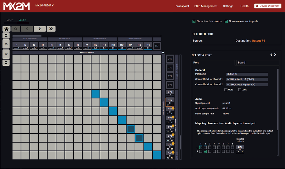
Crosspoint menu - Audio layer in the Lightware Device Controller software
Dante or AES67 audio signals can be routed to any other interface types within the matrix switcher. The Dante source signal can be embedded to the HDMI signal or transmitted to an analog audio sink device. De-embedded DisplayPort audio can also be transmitted as Dante audio to a network audio sink device.
The Dante audio settings are available in the Built-in website / Lightware Device Controller (LDC) software (details in the Dante® Audio Input Port Properties and Dante® Audio Output Port Properties sections) and using LW3 protocol commands (details in the Dante® Audio Settings section).
5.2.5. Multichannel Routing to the Outputs
This section explains how to be trasmitted a multichannel audio signal to the audio output ports of the matrix.
Example
In our example an 8-channel LPCM audio signal is required to transmit over the MX2M-AUX-DANTE-32CH auxiliary board of the matrix. The figure below shows the method that can be used for transmitting the 8 channels to the output ports.
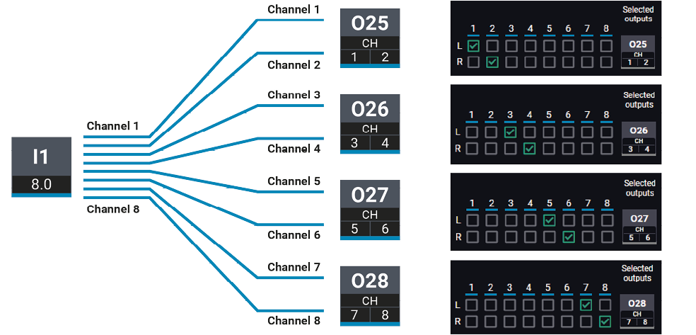
Example for multichannel audio signal routing
Required Settings
Step 1.Switch the input port (I1) to four output ports (O25; O26; O27; O28) in the crosspoint table. It can be done using one of the following methods:
▪via Lightware Device Controller (LDC) software - see the details in the Audio Layer section.
▪via LW3 protocol commands - see the details in the Switching an Input to an Output section.
Step 2.Set the channel mapping to select the desired channels for the output ports. Ensure that all input channels are routed to different output channels. The channel mapping can be done using one of the following methods:
▪via Lightware Device Controller (LDC) software - navigate to the Port properties panel of each selected output port by clicking on the output port icon and complete the channel mapping settings. See the details in the Dante® Audio Output Port Properties section.
▪via LW3 protocol commands - see the details in the Channel Mapping section.
5.2.6. Audio Signal Transmission - Example

The Concept
The matrix frame is installed with different types of I/O boards:
|
I/O board |
Connection interface |
Signal direction |
Connected device |
|
|
AUX |
MX2M-AUX-8AUDIO |
Analog audio cable with 5-pole Phoenix connector |
Input |
Microphone |
|
Output |
Active speakers |
|||
|
MX2M-AUX-DANTE-32CH |
CATx |
Input |
Dante media player over a network switch |
|
|
Output |
Dante audio amplifier over a network switch |
|||
|
IB |
MX2M-4HDMI20-IB |
HDMI |
Input |
Blu-ray player |
|
MX2M-4OPTJ-IB |
Multimode fiber optical |
Input |
4K PC over a HDMI20-OPTJ-TX90 fiber optical transmitter |
|
|
OB |
MX2M-4HDMI20-OB |
HDMI |
Output |
4K TV |
|
MX2M-4OPTJ-OB |
Multimode fiber optical |
Output |
4K projector over a HDMI20-OPTJ-RX90 fiber optical receiver |
|
Inputs
The matrix can receive audio signals from three types of sources:
▪Analog audio from the microphone - it is converted to 2-channel LPCM signal and routed to the Audio layer;
▪Digital embedded HDMI audio from the Blu-ray player - the signal is de-embedded and copied to the Audio layer.
▪AoE (Audio over Ethernet) audio signal from the Dante media player via the network - the digital audio signal is copied to the Audio layer.
Outputs
On the output side, the matrix can transmit three types of audio signals:
▪Analog audio signal to the active speakers - the transmitted audio signal can be 2-channel LPCM only. As the selected signal can include more than two audio channels, the user can select the two channels to be transmitted on the analog audio interface.
▪Digital embedded HDMI audio to the 4K TV - the embedded audio signal can be 2-channel LPCM or compressed (non-HBR) audio signal only. There are two possibilities in case of audio signal embedding:
=If the selected signal is of type LPCM, the user can select the two channels to be transmitted.
=If the selected signal is compressed (non-HBR) audio, it can be embedded into the video stream without any further action.
▪AoE (Audio over Ethernet) audio signal to the Dante audio amplifier via the network - the transmitted audio signal can be PCM 16 and PCM 24 audio signals up to 16 channels. If the selected signal includes more than two audio channels, the user can select the two channels to be transmitted.
See more details about the related settings in the Lightware Device Controller (LDC) software in the Audio Port Properties Windows section.
5.3. Consumer Electronics Control (CEC) Interface
Consumer Electronics Control (CEC) is a bi-directional communication, defined in the HDMI standard. This feature is for remote control of the source and sink devices in the AV system.
MX2M-4HDMI20 and MX2M-4OPTJ series I/O boards are able to send and receive CEC commands, from the input ports towards the source, and from output port towards the sink. For more information about sending CEC messages, see the CEC Controller (LDC) and the Sending CEC Commands (LW3 protocol commands) sections.
ATTENTION!CEC has a dedicated pin in the HDMI connector. DVI connector does not contain this pin, so the CEC transmission brakes when HDMI-DVI connector or adapter is in the signal route.
CEC Application Example
The matrix is able to send CEC commands over the HDMI and fiber optical ports to the sink and the source devices as well.
5.4. Signal Extension Methods
MX2M series matrix switchers offer several ways to extend the AV signal ranges. Beyond the traditional cable types (HDMI, DisplayPort), where the MX2M series I/O board uses signal compensation to extend the appliable cable lengths, the modular matrix offers more I/O boards that are able to extend the cable length to up to 2500 meters.
Featured MX2M series I/O Boards:
▪MX2M-AUX-DANTE-32CH - Dante / AES67 audio interface that is able to make connection between the auxiliary board and a network switch or Dante / AES67 capable source or sink device using CATx cables - see more details in the Audio Signal Extension over Dante Interface section.
▪MX2M-4OPTJ-IB / MX2M-4OPTJ-OB - Audio+video signal extension over a multimode fiber optical cable, up to 4K60 resolution. MX2M-4OPTJ series boards are fully compatible with the HDMI20-OPTJ-90 series optical extenders - see more details in the AV Signal Extension over Fiber Optical Cable section.
▪MX2M-4TPX-IB / MX2M-4TPX-OB - Audio+video signal extension over a CATx cable, up to 4K60 resolution. The output board is compatible with all HDMI-TPX-100 and HDMI-TPX-209 series point-to-point SDVoE receivers - see more details in the AV Signal Extension over SDVoE Interface section.
5.4.1. Audio Signal Extension over Dante Interface

Afffected Board:
The Concept
Digital AoE (Audio over Ethernet) signals can be received and transmitted over the Dante audio interface. The input signals can be routed to any interface within the matrix, for example it can be embedded into the HDMI output signal or transmitted as analog audio. The Dante output signal can be sourced from any other input signal type, for example it can be de-embedded from the HDMI signal or can be received from a microphone as analog audio input.
The Dante/AES67 signal extension can be maximalized using an L2/L3 managed network switch for the connections between the MX2M-AUX-DANTE-32CH board and the audio source and sink devices.
INFO:More information can be found about the network configuration in the Switch Setup for Dante® Audio Signal Transmission section.
See the details about the maximum cable extensions in the CATx Cable Distances for Dante section.
5.4.2. AV Signal Extension over Fiber Optical Cable

Afffected Boards:
The Concept
The MX2M-4OPTJ-IB and MX2M-4OPTJ-IB-E input boards can receive AV signals of up to 4K60 4:4:4 resolution over a single fiber optical cable. The boards are fully compatible with the Lightware HDMI20-OPTJ-TX90 fiber optical transmitter.
The MX2M-4OPTJ-OB and MX2M-4OPTJ-OB-E output boards can transmit AV signals of up to 4K60 4:4:4 resolution over a single fiber optical cable. The boards are fully compatible with the Lightware HDMI20-OPTJ-RX90 fiber optical receiver.
See the details about the maximum cable extensions in the Fiber Optical Cable Distances section.
5.4.3. AV Signal Extension over SDVoE Interface

Afffected Boards:
The Concept
The MX2M-4TPX-IB input board can receive AV signals of up to 4K60 4:4:4 resolution over a single CATx cable. User Ethernet signal can also be transmitted together with the AV signals. The board is fully compatible with the Lightware HDMI-TPX-TX106 / TX107 and HDMI-TPX-TX209 series SDVoE transmitters.
MX2M-4TPX-OB output board can transmit AV signals of up to 4K60 4:4:4 resolution over a single CATx cable. User Ethernet signal can also be transmitted together with the AV signals. The boards are fully compatible with the Lightware HDMI-TPX-RX106 / RX107 and HDMI-TPX-RX209 series SDVoE receivers.
INFO:Lightware recommends HDMI-TPX-107 and -209 series extenders for the matrix because of the PoE-supplement. HDMI-TPX-106 series extenders are not PoE-capable devices however they are fully compatible with the MX2M-4TPX series I/O boards.
See the details about the maximum cable extensions in the CATx Cable Distances for TPX section.
Remote Power Capability
The TPX series input and output boards are PoE-compatible, which means they are able to provide 48V power to the connected HDMI-TPX series transmitters or receivers or any third-party SDVoE extender devices. The boards are able to send power over all four TPX ports at the same time.
ATTENTION!The matrix frame must be built with an MX2M-PSU-1250-FP power drawer to fulfill the remote powering option. For more details, see the Model Comparison section.
5.5. Ethernet Layer
INFO:All three Ethernet ports of matrix (Secure Control; Uplink; Uplink/Secure Control) are equivalent and they can be used for controlling the system.
5.5.1. Control Mode
The matrix can be controlled using the three Ethernet ports with Neutrik RJ45 connectors, which provide 1 GbE data transmission each. The ports accept cables built with Neutrik and RJ45 connectors as well.
The device can be controlled over the Ethernet interface using different methods. See the details about it in the Software Control Modes section.
5.5.2. Firmware Update Mode
The firmware update of the matrix frame can be applied over the Ethernet interface using the Ethernet ports.
The firmware files of the I/O boards are built in the firmware package of the matrix. The firmware update of the I/O boards is done over the internal Ethernet layer. See the details about the firmware update procedure in the Firmware Updating of the I/O Boards section.
5.5.3. User Ethernet Mode
The MX2M series matrix switchers use the User Ethernet mode, which acts roughly as an unmanaged Ethernet switch from the point of the customer. The User Ethernet mode provides three equal ports for the customer UP1, UP2 and UP3.
Limitations
Since the MX2M Ethernet network transfers internal audio streams and control frames as well, there are some limitations:
▪VLAN ID 100 cannot be used, it is reserved for the internal control frames;
▪VLAN ID 300 cannot be used, it is reserved for the internal audio streams.
ATTENTION!Customer frames with PCP 7 should be avoided in order to preserve the internal audio stream transfer.
5.6. Licensing
MX2M-FR24R matrix switcher can be purchased with no PSU redundancy. In this case only one PSU drawer is installed with a power supply unit (Power Drawer 1, Primary) and the Single PSU License is installed on matrix. In this case, the Power Drawer 2 cannot accept the second PSU drawer. Customers have possibility purchasing a code which makes the Single PSU License inactive. For more details please contact sales@lightware.com.
You can check, add or remove licenses to the system with two methods:
▪via Built-in website / Lightware Device Controller (LDC) software - see the details in the Overview section;
▪using LW3 protocol commands - see the details in the Adding License and Removing License sections.
5.7. Further Built-in Features
5.7.1. Device Cloning – Configuration Backup and Restore

The device (configuration) cloning of MX2M matrix switcher is a simple method that eliminates the need to repeatedly configure certain devices to have identical (non-factory) settings. If the devices are installed in the same type of system multiple times, then it is enough to set up only one device to fit the user’s needs and then copy those settings to the others, thus saving time and resources.
See more information about the settings in the System section.
5.7.2. Advanced EDID Management
Factory Preset EDIDs
The factory EDIDs (F1-F148) are factory preprogrammed and cannot be modified. These are the most common signal formats. They are specially provided to force graphic cards to output only the exact pixel resolution and refresh rate.
Universal EDID allows multiple resolutions including all common VESA defined resolutions. The use of universal EDID is recommended for fast and easy system setup.
Sources and Destinations
The EDID memory consists of four parts:
▪Factory EDID list shows the pre-programmed EDIDs (F1-F148).
▪Dynamic EDID list shows the sink connected to the device's outputs (D1-D24). The unit stores the last display devices’ EDID on either output, so there is an EDID shown even if there is no display device attached to the output port at the moment.
▪User memory locations (U1 – U100) can be used to save custom EDIDs.
▪Emulated EDID list shows the currently emulated EDID for the inputs (E1-E24). The source column displays the memory location that the current EDID was routed from.
The source reads the EDID from the Emulated EDID memory on the input port. Any EDID from any of the User/Factory/Dynamic EDID lists can be copied to the emulated EDID memory.
There are two types of emulation: static and dynamic.
▪Static EDID emulation: an EDID from the Factory or User EDID list is selected. Thus, the Emulated EDID remains the same until the user emulates another EDID.
▪Dynamic EDID emulation: it can be enabled by selecting D1-D24 EDID memory. The attached monitor’s EDID is copied to the input; if a new monitor is attached to the output, the emulated EDID changes automatically.
See more information about the settings in the EDID Management Menu section in the LDC software.
User has more possibilities to control the device besides the front panel buttons. The following list contains the software control modes:
▪Built-in website / Lightware Device Controller (LDC): you can connect to the device via our control software with using USB, RS-232 or Ethernet interfaces and control or configure the device as you wish. For the details, see the Software Control - Lightware Device Controller chapter.
▪LW3 protocol commands: you can configure the device by using the full-range command set of LW3 protocol. For more details, see the LW3 Programmers' Reference chapter.
6. Software Control - Built-in Website
The built-in website of the Matrix Management Unit allows to connect to and control the matrix via a web browser. The range of the controlling features are the same as in the case of Software Control - Lightware Device Controller.
System Requirements
Operating System: Microsoft Windows 10, Apple macOS, Linux.
Web Browser: Mozilla Firefox, Google Chrome, Apple Safari.
ATTENTION!The EDID export function works only in Windows and macOS operating systems under Mozilla Firefox or Google Chrome web browsers.
6.1. Establishing the Connection
ATTENTION!Please make sure that the computer is in the same network as the matrix switcher. If the computer has multiple Ethernet connections (for example Wi-Fi and LAN connections are used simultaneously), you will need to know the IP address for the one that is used for controlling the system. #builtinweb #web
Step 1.Connect the matrix and the computer either via
▪Ethernet, with LAN patch cable, or
▪Ethernet, with LAN cross cable.
Step 2.Change to the desired IP settings if needed.
Step 3.Type the IP address to the address bar of the web browser and press enter (the factory default network setting is the DHCP (dynamic IP address).
6.2. The Layout of the Built-in Web
The built-in web page allows the same controlling functions that are available via the Lightware Device Controller. Select a menu item on the left side; the default screen is the Crosspoint menu.
ATTENTION!Please enable the pop-up windows in your browser; certain contents are only displayed in a new window.

Built-in website of the MX2M-FR24R matrix switcher
7. Software Control - Lightware Device Controller
The device can be controlled by a computer through the Ethernet interface with the Lightware Device Controller (LDC). The software can be installed on a Windows PC or macOS. The application and the User’s Manual can be downloaded from www.lightware.com.
7.1. Install and Update
INFO:After the installation, the Windows and the macOS applications have the same look and functionality.
Minimum System Requirement
RAM: 1 GB
Minimum display resolution: 1280x720
Installation for Windows OS
Run the installer. If the User Account Control drops a pop-up message, click Yes.
During the installation you will be prompted to select the type of the installation: normal and the snapshot install:
|
Normal install |
Snapshot install |
|
Available for Windows and macOS |
Available for Windows |
|
The installer can update only this instance |
Cannot be updated |
|
Only one updateable instance can exist for all users |
More than one different version can be installed for all users |
Comparison of installation types
ATTENTION!Using the Normal install as the default choice is highly recommended.
Installation for macOS
Mount the DMG file by double clicking on it, and drag the LDC icon over the Applications icon to copy the program into the Applications folder. If you want to copy the LDC into another location, just drag the icon over the desired folder.
Updating of LDC
Step 1.Run the application.
The Device Discovery window appears automatically, and the program checks the available updates on Lightware’s website and opens the update window if the LDC found updates.
The current and the update version number can be seen at the top of the window and they are shown in this window even with the snapshot install.
The Update window can also be opened by clicking on the About  icon and the Update button.
Step 2.Set the desired update setting in the Options section.
▪If you do not want to check for the updates automatically, uncheck the circle that contains the green tick.
▪If you want to postpone the update, a reminder can be set with different delays from the drop down list.
▪If the proxy settings traverse the update process, set the proper values, then click on the OK button.
Step 3.Click on the Download update button to start the update.
The updates can be checked manually by clicking on the Check now button.
7.2. Running the LDC
The common way to start the software is to double-click on the LDC icon. But the LDC can be run by command line parameters as follows.
ATTENTION!Please check the firewall settings on the macOS device. LDC needs to be added to the exeptions of the blocked softwares for the proper operation.
Connecting to a Device with Static IP Address
Format: LightwareDeviceController -i <IP_address>:<port>
Example: LightwareDeviceController -i 192.168.0.20:6107
The LDC is connected to a device with the indicated static IP address directly; the Device Discovery window is not displayed. When the port number is not set, the default port is used: 10001 (LW2 protocol). For LW3, devices use the 6107 port number.
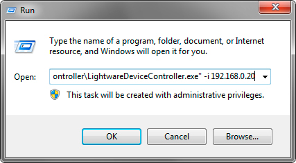
Run window in Windows OS

Step 1.Connect the device to a computer via the following methods:
▪Ethernet
▪RS-232
▪USB
Changing IP Address 
To modify IP address settings quickly, it is not necessary to enter the device's settings/network menu, you can set them by clicking on the pencil icon next to the IP address. #network #ipaddress #dhcp
You can see the new settings only in this window.
Step 2.Run the controller software; the device discovery window appears automatically.
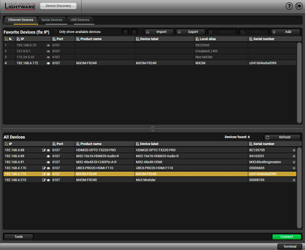
Device discovery window in LDC
Step 3.Select the MX2M-FR24R device from the discovered Ethernet devices or Serial devices; when the device is connected through RS-232, click on the Query button next to the desired serial port to display the name of the device and the serial number. Double click on the device name or select the device, and click on the green Connect button.

DIFFERENCE:This feature is available in LDC since v2.5.5.
Press the Add button; in the appearing window you can enter the IP address. The hostname of the desired device can be used instead, if it is supported. That allows setting a unique name to identify the device in a network. If the host name is saved in this window and the IP address is changing, the device will still be available and connectible.
ATTENTION!The host name connection-feature does not work when the target device is accessed over VPN.
Import/Export the List of Favorite Devices
DIFFERENCE:This feature is available in LDC since v2.5.5.
The list of favorite devices can be exported/imported by the dedicated buttons (saved as *.JSON file). The list can be imported later (in another computer, too), but please note that the current list will be overwritten by the imported list.
Changing the IP Address
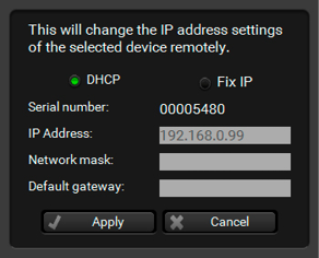
To modify the IP address settings quickly, it is not necessary to enter the device's settings/network menu, you can set them by clicking the pencil icon beside the IP address.
You can see the new settings only in this window. The device needs a few seconds to apply the new settings. #ipaddress
Identifying the Device 
Clicking on the icon results in the blinking of the status LEDs for 10 seconds. The feature helps to find the device itself physically.
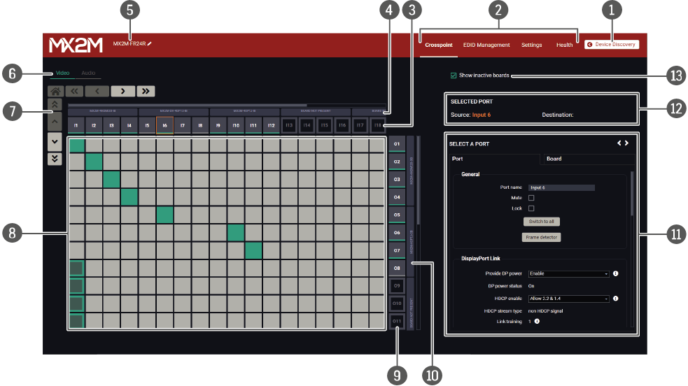
Crosspoint menu - Video layer
Legend of the Crosspoint Menu
|
|
Device Discovery |
Clicking on the button results in returning to the Device Discovery window. The connection with the current device will be terminated. |
|
|
Main menu |
The available menu items (Crosspoint Menu, EDID Management Menu, Settings Menu and Health Menu) are displayed. The Terminal Window window is available under the Settings menu. |
|
|
Source streams |
Each tile represents a video stream coming from one of the input ports of the input boards (IB). Clicking on the tile opens the Video Port Properties Windows on the right side. |
|
|
Input Boards |
The grey bars group the destination ports belonging to a single input board. Board not present description means there is no input board seated to the frame or the board is unavailable. Enabling the Show inactive boards switcher shows the inactive boards in the crosspoint table. |
|
|
Device label |
The device label of the matrix is displayed here. It can be modified by the user to any unique name by clicking on the |
|
|
Layer tabs |
The Video Layer and the Audio Layer crosspoint panel can be selected on the tabs. |
|
|
Navigation buttons |
Clicking on the navigation buttons shows the available sources/destinations and crosspoints that cannot be displayed within the initial window size. The |
|
|
Connections |
The crosspoint connections can be selected in this table. |
|
|
Destination ports |
Each tile represents an output port of the output boards (OB). Clicking on the tile opens the Video Port Properties Windows on the right side. |
|
|
Output boards |
The grey bars group the destination ports belonging to a single output board. Board not present description means there is no output board seated to the frame or the board is unavailable. Enabling of the Show inactive boards switcher shows the inactive boards in the crosspoint table. |
|
|
Properties window |
The properties, available settings, and status information of the selected source or destination are displayed in this section. Two tabs are available: Port and Board. See more details about the port settings in the Video Port Properties Windows section. |
|
|
Selected / Highlighted streams |
Showing the currently selected connections. Move the cursor above the desired crosspoint and the names of the source and destination are displayed in the field. |
|
|
Show inactive boards switcher |
When it is enabled, the inactive boards are shown in the crosspoint table. When it is disabled, the inactive boards are hidden. |


INFO:See the details about the port and crosspoint tiles in the Legend of the Port Tiles section.
INFO:See more details about video input/output port numbering in the Video Input/Output Port Numbering section.
#switch #crosspoint #label #devicelabel
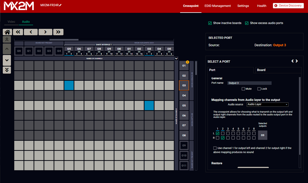
Crosspoint menu - Audio layer
The operation of the Audio layer is basically the same as the Video Layer.
Clicking on the source or the destination port the properties panel opens on the right side - all audio related information and options are available here. See the details about the available settings in the Audio Port Properties Windows section. #audio #analogaudio #switch #crosspoint
INFO:See the details about the port, and crosspoint tiles in the Legend of the Port Tiles section.
INFO:See more details about audio input/output port numbering in the Audio Input Port Numbering and the Audio Output Port Numbering sections.
Dante / AES67 Crosspoint Settings
ATTENTION!Please note that the Dante/AES67 crosspoint operations in the LDC application affects the signal routing within the matrix switcher only. For external Dante/AES67 sources and destinations, please use the Dante Controller application. See the details in the Dante® Audio Interface section.
7.4.3. Legend of the Port Tiles
This section helps to easily identify the various types of port and crosspoint tiles on the Crosspoint menu.
Video Layer
|
Port tile |
Description |
|
Port tiles |
|

|
Port is not available, because there is no I/O board is installed in the related board slot. |

|
Port is available, but there is no AV signal transmission. |

|
Port is available and there is AV signal transmission. |
|
Crosspoint tiles |
|

|
No crosspoint connection. |

|
Crosspoint connection is set, but there is no signal on the selected input port. |

|
Crosspoint connection is set and the signal transmission is on. |
Audio Layer
|
Port tile |
Description |
|
Port tiles |
|
|
|
Port is not available, because there is no I/O board is installed in the related board slot. |

|
In case of output ports of the MX2M-AUX-8AUDIO board only: The port on the board is configured as an analog audio input. |

|
There is no AV signal transmission on the selected input port (signal is undefined). |

|
Input port is available and there is signal transmission on the selected audio port (for example 2-channel PCM (2.0). |

|
There is no AV signal transmission on the selected output port, or the incoming signal is not 2-channel LPCM or uncompressed HBR audio. User needs to define the two audio channel that are to be transmitted - it can be done on the Digital Audio Output Port Properties and the Analog Audio Output Port Properties sections. |

|
Output port is available for signal transmission. |
|
Port tile |
Description |
|
Crosspoint tiles |
|
|
|
No crosspoint connection. |

|
Unavailable crosspoint. |

|
Crosspoint connection is set, but there is no signal on the selected input port. |

|
Crosspoint connection is set and the signal transmission is on. |
7.5. Video Port Properties Windows
7.5.1. HDMI / OPTJ Input Port Properties

DIFFERENCE:The following panel is available only when a MX2M-4HDMI20-IB or MX2M-4OPTJ-IB board is installed in the matrix frame.
Clicking on a HDMI or OPTJ input port icon opens the Port properties panel. The most important signal information and settings are available from the panel. #hdmi #optj
Port Tab
Available Settings and Tools
▪Port naming
▪Mute/Unmute switcher #mute #unmute
▪Lock/Unlock switcher #lock #unlock
▪Switch to all button: clicking on the button switches the selected input stream to all output ports. #switch
▪Frame Detector - The tool displays the frame information of the input stream coming from the input port. #framedetector
▪CEC Controller - The tool is for the remote control of the source or sink device.
▪Maximum supported HDCP version (HDCP disabled / HDCP 1.4 / HDCP 2.2); #hdcp
▪HPD enable (Hot Plug Detect) enable button (Auto / On / Off); #hdp #hotplugdetect
▪Video stream information;
▪Embedded audio information
▪Restore Factory Default Settings button.
Board Tab
The most important information about the I/O board is available on the tab like the type of the board and the status of board.
7.5.2. DisplayPort Input Port Properties

DIFFERENCE:The following panel is available only when a MX2M-DH-4DP12-IB board is installed in the matrix frame.
Clicking on a DP input port icon opens the Port properties panel. The most important signal information and settings are available from the panel. #displayport #dp
Port Tab
Available Settings and Tools
▪Port naming
▪Mute/Unmute switcher #mute #unmute
▪Lock/Unlock switcher #lock #unlock
▪Switch to all button: clicking on the button switches the selected input stream to all output ports. #switch
▪Frame Detector - The tool displays the frame information of the input stream coming from the input port. #framedetector
▪Provide DP power (Enable / Disable): if enabled, the board sends 1.5W power on the chosen port. #dppower
▪HDCP enable (Disable / Allow 1.4 only / Allow 2.2 & 1.4 / High value mode); #hdcp
▪Link datarate (Max RBR 1.62 Gbps / Max HBR 2.7 Gbps / Max HBR2 5.4 Gbps);
▪Link lane count (Max 1 lanes / Max 2 lanes / Max 4 lanes);
▪Conversion mode (Passthrough / RGB 4:4:4 to YCbCr 4:2:2 12 bit / RGB 4:4:4 to YCbCr 4:2:0 8 bit); #colorspace
▪Restart link training button; #linktraining
▪Video stream information;
▪Embedded audio information.
▪Restore Factory Default Settings button.
Board Tab
The most important information about the I/O board is available on the tab like the type of the board and the status of board.
7.5.3. TPX Input Port Properties
DIFFERENCE:The following panel is available only when a MX2M-4TPX-IB board is installed in the matrix frame.
Clicking on a TPX input port icon opens the Port properties panel. The most important signal information and settings are available from the panel. #tpx
Port Tab
Available Settings and Tools
▪Port naming
▪Mute/Unmute switcher #mute #unmute
▪Lock/Unlock switcher #lock #unlock
▪Switch to all button: clicking on the button switches the selected input stream to all output ports. #switch
▪Frame Detector - The tool displays the frame information of the input stream coming from the input port. #framedetector
▪CEC Controller - The tool is for the remote control of the source or sink device.
▪PoE state and PoE enable setting - enabling of PoE setting allows to send power to the connected TPX extender (false / true). #poe
▪Maximum supported HDCP version (HDCP disabled / HDCP 1.4 / HDCP 2.2); #hdcp
▪HPD enable (Hot Plug Detect) enable button (Auto / On / Off); #hdp #hotplugdetect
▪Video stream information;
▪Embedded audio information.
▪Restore Factory Default Settings button.
Board Tab
The most important information about the I/O board is available on the tab like the type of the board and the status of board.
7.5.4. HDMI / OPTJ Output Port Properties
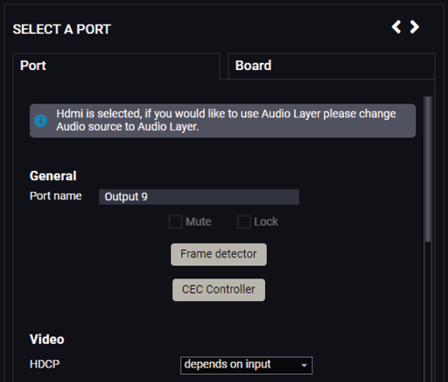
DIFFERENCE:The following panel is available only when a MX2M-4HDMI20-OB or MX2M-4OPTJ-OB board is installed in the matrix frame.
Clicking on a HDMI or OPTJ output port icon opens the Port properties panel. #hdmi #optj
Port Tab
Available Settings and Tools
▪Port naming
▪Mute/Unmute switcher #mute #unmute
▪Lock/Unlock switcher #lock #unlock
▪Frame Detector - The tool displays the frame information of the input stream coming from the input port. #framedetector
▪CEC Controller - The tool is for the remote control of the source or sink device.
▪HDCP: #hdcp
=Depends on input: the level and version of HDCP-encryption depends on the source device;
=Maximum possible: the output ports set the maximum HDCP-encryption level that the connected sink device can accept.
▪5V enable switcher (on / off / auto); #power5v
▪Conversion mode (Passthrough / YCbCr 4:2:2); #colorspace
▪Video stream information;
▪Audio source: #embedder #audio
=HDMI: the original embedded audio is transmitted with the stream. When the crosspoint connection is changed on the Video layer, the embedded audio will be changed as well.
=Audio layer: the audio signal is selected from the Audio layer. *
=OFF: audio signal is disabled.
▪Mapping channels for Audio layer to the output: the embedded audio signal can be 2-channel LPCM or compressed (non-HBR) audio signal only. There are two possibilities in case of audio signal embedding:
=If the selected signal includes more than two audio channels, the user can select the two channels that are to be transmitted.
=If the selected signal is compressed (non-HBR) audio, it can be embedded into the video stream without any further action. #mapping #channelmapping
▪Restore Factory Default Settings button.
Board Tab
The most important information about the I/O board is available on the tab like the type of the board and the status of board.
7.5.5. TPX Output Port Properties

DIFFERENCE:The following panel is available only when a MX2M-4TPX-OB board is installed in the matrix frame.
Clicking on a TPX output port icon opens the Port properties panel. #tpx
▪Port naming
▪Mute/Unmute switcher #mute #unmute
▪Lock/Unlock switcher #lock #unlock
▪Frame Detector - The tool displays the frame information of the input stream coming from the input port. #framedetector
▪PoE state and PoE enable setting - enabling of PoE setting allows to send power to the connected TPX extender (false / true). #poe
▪HDCP: #hdcp
=Depends on input: the level and version of HDCP-encryption depends on the source device;
=Maximum possible: the output ports set the maximum HDCP-encryption level that the connected sink device can accept.
▪5V enable switcher (on / off / auto); #power5v
▪Conversion mode (Passthrough / YCbCr 4:2:2); #colorspace
▪Video stream information;
▪Audio source: #embedder #audio
=Original embedded audio: the original embedded audio is transmitted with the stream. When the crosspoint connection is changed on the Video layer, the embedded audio will be changed as well.
=Audio layer: the audio signal is selected from the Audio layer.
=OFF: audio signal is disabled.
Board Tab
The most important information about the I/O board is available on the tab like the type of the board and the status of board.
The ports can show detailed information about the signal like blanking intervals and active video resolution. This feature can be used for troubleshooting if compatibility problems occur during system installation. To access this function, open the port properties window and click on the Frame detector button.

Frame detector window
Lightware’s Frame Detector function works like a signal analyzer and allows to determine the exact video format that is present on the port, thus it helps to identify various problems. E.g. actual timing parameters may differ from the expected and this may cause some displays to drop the picture.
Frame Detector measures detailed timings of the video signals just like a built-in oscilloscope, but it is much easier to use. Actual display area shows the active video size (dark grey). Black area of the full frame is the blanking interval, which can contain the info frames and embedded audio data for HDMI signals. Shown values are measured on the actual signal and not retrieved only from the HDMI info frames. #framedetector
DIFFERENCE:The following panel is available only when a MX2M-4HDMI20-IB, MX2M-4OPTJ-IB, MX2M-4TPX-IB, MX2M-4HDMI20-OB or MX2M-4OPTJ-OB board is installed in the matrix frame.
The MX2M-4HDMI20 and MX2M-4OPTJ series I/O boards are able to send and receive Consumer Electronics Control (CEC) commands. This feature is for remote control of the source or sink device. CEC is a bi-directional communication via HDMI cable.
ATTENTION!It can occur that the third-party device can receive, but not execute the command because it is not supported by the product. Check the accepted commands in the documentation of the device.
INFO:The first 2x2 bytes of the CEC commands contain identification data of the source and destination address. When the port is input, it is always 04 (from TV to Playback device 1.); when the port is output, it is always 40 (from Playback device 1. to TV).
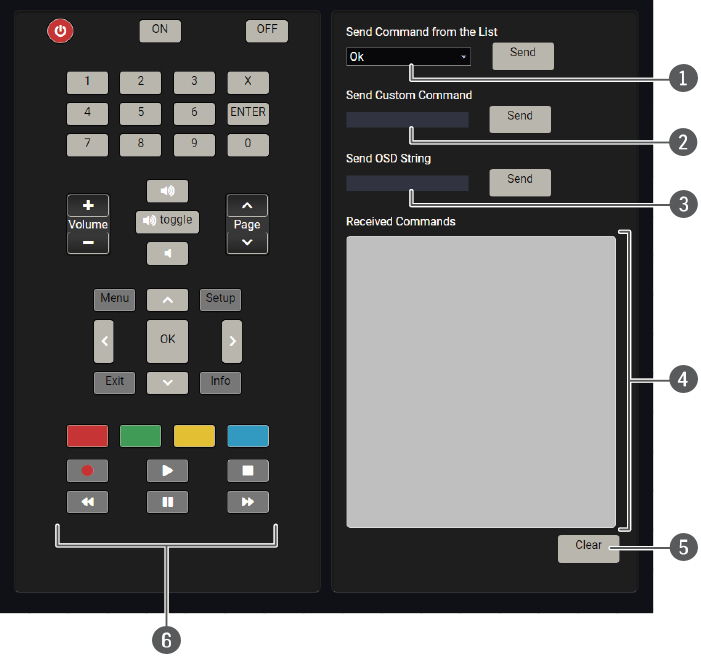
The CEC panel is available on the port properties window of the HDMI input, HDMI output, OPTJ input and OPTJ output ports.
CEC control panel on the HDMI out port properties window
|
|
Drop-down command list |
This list contains the basic CEC commands, most of them are displayed on the graphical interface, too (on the left side). Click on the Send button to send the command. |
|
|
Custom command textbox |
The text field is for sending hexadecimal commands to the source. The maximum length of the message could be 30 characters (15 bytes). Click on the Send button to send the command. |
|
|
OSD string textbox |
A max. 14-character-long text can be shown on the sink device. The send OSD (On-screen display) command textbox is the input field of the string. Alphanumeric characters, glyphs and space are accepted. Click on the Send button to execute the command. |
|
|
Received Command box |
Displays all the sent (in red) CEC commands and the received answers (in blue) with a timestamp. Legend of the received message: < [10:33:17] ACK Answer for the acknowledged command. < [10:35:01] NACK Answer for the not acknowledged command. < [10:33:17] IN PROGRESS The command is in progress at the moment. < [10:33:17] FAILED Answer for other failure. < [10:35:40] feature_abort_<*> This is the most common answer from the third-party devices when the command is delivered, but the execution is refused. The cause of the refusal stands after 'feature_abort' expression. |
|
|
Clear button |
Click on the Clear button to erase the content of the terminal window. |
|
|
CEC command button panel |
This panel provides quick and easy management of CEC commands. These buttons are pre-programmed with basic functions and send commands towards the sink. The communication is displayed in the Received Command box. For the list of the commands, see Sending a CEC Command in Hexadecimal Format section. Both the layout and functionality are similar to the design of a remote control. |
ATTENTION!Make sure that the controlled unit is CEC-capable and this function is enabled.
#cec
7.6. Audio Port Properties Windows
7.6.1. Digital Audio Input Port Properties
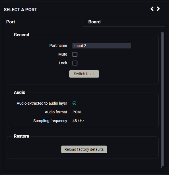
DIFFERENCE:The following panel is available only when a MX2M-4HDMI20-IB, MX2M-4OPTJ-IB, MX2M-4TPX-IB or MX2M-DH-4DP12-IB board is installed in the matrix frame.
Clicking on a digital audio input port icon opens the Port properties panel. The most important signal information and settings are available from the panel. #audio #hdmi #optj #displayport #dp
Port Tab
Available Settings and Tools
▪Port naming
▪Mute/Unmute switcher #mute #unmute
▪Lock/Unlock switcher #lock #unlock
▪Switch to all button: clicking on the button switches the selected input stream to all output ports. #switch
▪Audio signal related information;
▪Restore Factory Default Settings button.
Board Tab
The most important information about the I/O board is available on the tab like the type of the board and the status of board.
7.6.2. Digital Audio Output Port Properties
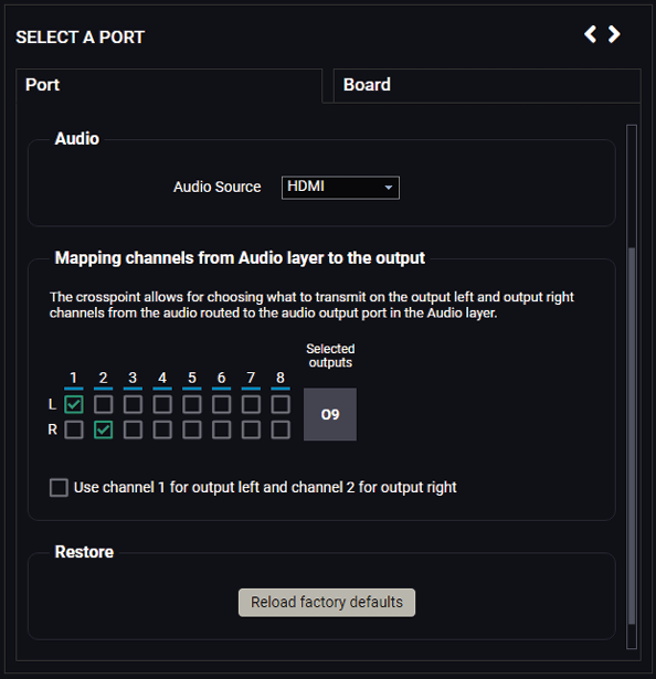
DIFFERENCE:The following panel is available only when a MX2M-4HDMI20-OB, MX2M-4OPTJ-OB or MX2M-4TPX-OB board is installed in the matrix frame.
Clicking on a HDMI or OPTJ output port icon opens the Port properties panel. The most important signal information and settings are available from the panel. #audio #hdmi #optj
Port Tab
Available Settings and Tools
▪Port naming
▪Mute/Unmute switcher #mute #unmute
▪Lock/Unlock switcher #lock #unlock
▪Audio source: #embedder
=HDMI: the original embedded audio is transmitted with the stream. When the crosspoint connection is changed on the Video layer, the embedded audio will be changed as well.
=Audio layer: the audio signal is selected from the Audio layer. *
=OFF: audio signal is disabled.
▪Mapping channels for Audio layer to the output: the embedded audio signal can be 2-channel LPCM or compressed (non-HBR) audio signal only. There are two possibilities in case of audio signal embedding:
=If the selected signal is of type LPCM, the user can select the two channels that are to be transmitted.
=If the selected signal is compressed (non-HBR) audio, it can be embedded into the video stream without any further action. #mapping #channelmapping
▪Restore Factory Default Settings button.
Board Tab
The most important information about the I/O board is available on the tab like the type of the board and the status of board.
7.6.3. Analog Audio Input Port Properties

DIFFERENCE:The following panel is available only when a MX2M-AUX-8AUDIO board is installed in the matrix frame.
Clicking on an analog audio input port icon opens the Port properties panel. The most important signal information and settings are available from the panel. #audio #analogaudio
Port Tab
Available Settings and Tools
▪Port naming
▪Mute/Unmute switcher #mute #unmute
▪Lock/Unlock switcher #lock #unlock
▪Switch to all button: clicking on the button switches the selected input stream to all output ports. #switch
▪Input gain: sets the gain between -12 dB and 21 dB. Clicking on the  icon results in -1 dB, the
  icon results in +1 dB in the gain setting. The default value is 0 dB. #gain
▪Input volume: sets the input volume (attenuation) between 0% (-95.625 dB) and 100% (0 dB). Clicking on the icon results in -1%, the icon results in +1% in the volume setting. The default value is 100%. #volume
▪Input balance: sets the balance between -100 (total left) and 100 (total right). Clicking on the icon results in -1, the icon results in +1 in the balance setting. The default value is 0 (center). #balance
▪Restore Factory Default Settings button.
Board Tab
The most important information about the I/O board is available on the tab like the type of the board and the status of board.
7.6.4. Analog Audio Output Port Properties

DIFFERENCE:The following panel is available only when a MX2M-AUX-8AUDIO board is installed in the matrix frame.
Clicking on an analog audio output port icon opens the Port properties panel. The most important signal information and settings are available from the panel. #audio #analogaudio
Port Tab
Available Settings and Tools
▪Port naming
▪Mute/Unmute switcher #mute #unmute
▪Lock/Unlock switcher #lock #unlock
▪Output volume: sets the volume (attenuation) between 0% (-95.625 dB) and 100% (0 dB). Clicking on the icon results in -1%, the icon results in +1% in the volume setting. The default value is 100%. #volume
▪Output balance: sets the balance between -100 (total left) and 100 (total right). Clicking on the icon results in -1, the icon results in +1 in the balance setting. The default value is 0 (center). #balance
▪Mapping channels for Audio layer to the output: analog audio output port can convert only LPCM signals, therefore the only option available is the following: if the selected signal is of type LPCM, the user can select the two channels to be transmitted. #mapping #channelmapping
▪Restore Factory Default Settings button.
Board Tab
The most important information about the I/O board is available on the tab like the type of the board and the status of board.
7.6.5. Dante® Audio Input Port Properties
DIFFERENCE:The following panel is available only when a MX2M-AUX-DANTE-32CH board is installed in the matrix frame.
Clicking on a Dante audio input port icon opens the Port properties panel. The most important signal information and settings are available from the panel. #audio #dante #aes67
Port Tab
Available Settings and Tools

▪Port naming
▪Adding Channel label for receive channel 1 and 2
▪Mute/Unmute switcher #mute #unmute
▪Lock/Unlock switcher #lock #unlock
▪Switch to all button: clicking on the button switches the selected input stream to all output ports. #switch
▪Restore Factory Default Settings button.
Board Tab
▪Device naming
▪IP address mode for Primary and Secondary interfaces: Unknown/Query / LinkLocal / DHCP or LinkLocal / DHCP / Static
▪TX channel naming: from TX channel 1 to 16.
▪RX channel naming: from RX channel 1 to 16.
▪Restore Factory Default Settings button.
7.6.6. Dante® Audio Output Port Properties

DIFFERENCE:The following panel is available only when a MX2M-AUX-DANTE-32CH board is installed in the matrix frame.
Clicking on a Dante audio output port icon opens the Port properties panel. The most important signal information and settings are available from the panel. #audio #dante #aes67
Port Tab
Available Settings and Tools
▪Port naming
▪Mute/Unmute switcher #mute #unmute
▪Lock/Unlock switcher #lock #unlock
▪Mapping channels for Audio layer to the output: the embedded audio signal can be 2-channel LPCM only. If the selected signal includes more than two audio channels, the user can select the two channels to be transmitted. #mapping #channelmapping
▪"Use channel 1 for output left and channel 2 for output right if the above mapping produces no sound" switcher
▪Restore Factory Default Settings button.
Board Tab
▪Device naming
▪IP address mode for Primary and Secondary interfaces: Unknown/Query / LinkLocal / DHCP or LinkLocal / DHCP / Static
▪TX channel naming: from TX channel 1 to 16.
▪RX channel naming: from RX channel 1 to 16.
▪Restore Factory Default Settings button.
Select the Crosspoint / Presets menu to open the preset operations of the matrix. #preset
The router can store presets and the following are stored in each slot: input/output crosspoint state, muted/unmuted states. Preset loading has an effect on all ports, except the locked ones.
ATTENTION!When factory default settings are restored, presets are deleted.
ATTENTION!The Preset loading has an effect on all ports, except the locked ones.

Preset menu
Loading a Preset
Step 1.Select the Presets tab from the Crosspoint menu.
Step 2.Select the desired preset; check the Preview panel and press the Load button. Press Yes in the confirmation window.
Auto load mode

When the Auto load button is highlighted in green, the mode is active. In this case, confirmation is not required: the selected preset is loaded immediately when the button is pressed.
Saving a Preset to an Empty Slot
Step 1.Arrange the desired crosspoint connections in Tile view or Grid view.
Step 2.Select the Presets tab from the Crosspoint menu and type the desired Preset name in the indicated text field up to 16 characters. The following are allowed when naming: letters (A-Z and a-z), hyphen (-), underscore (_), and numbers (0-9).
Step 3.Press the Create New Preset button to store the configuration.
Overwriting an Existing Preset
Step 1.Arrange the desired crosspoint connections.
Step 2.Select an existing preset, press the Save button and Yes to confirm.
Renaming a Preset
Step 1.Select the desired preset you want to rename.
Step 2.Type the desired name and press the Rename Preset button.
Deleting a Preset
Step 1.Select the desired preset you want to delete.
Step 2.Press the Delete button and Yes to confirm.
Advanced EDID Management can be accessed by selecting the EDID Management menu. There are two panels: the left one contains Source EDIDs, the right one contains Destination places where the EDIDs can be emulated or copied. #edid

EDID Management menu
Control Buttons

|
Exporting an EDID (save to a file) |
|
Transfer button: executing EDID emulation or copying |

|
Importing an EDID (load from a file) |

|
Deleting EDID (from User memory) |

|
Display EDID Summary window |

|
Selecting all memory places in the right panel |

|
Opening Advanced EDID Editor with the selected EDID |

|
Selecting none of the memory places in the right panel |

|
Opening Easy EDID Creator |
Changing Emulated EDID
Step 1.Choose the desired EDID list on the source panel and select an EDID.
Step 2.Press the Emulated button on the top of the Destination panel.
Step 3.Select the desired port on the right panel (one or more ports can be selected); the EDID(s) will be highlighted with a yellow cursor.
Step 4.Press the Transfer button to change the emulated EDID.
Learning an EDID
The process is the same as changing the emulated EDID; the only difference is the Destination panel: press the User button. Thus, one or more EDIDs can be copied into the user memory either from the factory memory or from a connected sink (Dynamic).
Exporting an EDID

Source EDID can be downloaded as a file (*.bin, *.dat or *.edid) to the computer.
Step 1.Select the desired EDID from the Source panel (line will be highlighted in yellow).
Step 2.Press the Export button to open the dialog box and save the file to the computer.
Importing an EDID

Previously saved EDID (*.bin, *.dat or *.edid file) can be uploaded to the user memory:
Step 1.Press the User button on the top of the Source panel and select a memory slot.
Step 2.Press the Import button below the Source panel.
Step 3.Browse the file in the opening window, then press the Open button. The browsed EDID is imported into the selected User memory.
ATTENTION!The imported EDID overwrites the selected memory place even if it is not empty.
Deleting EDID(s)

The EDID(s) from User memory can be deleted as follows:
Step 1.Press the User button on the top of the Destination panel.
Step 2.Select the desired memory slot(s); one or more can be selected (“Select All” and “Select None” buttons can be used). The EDID(s) will be highlighted in yellow.
Step 3.Press the Delete selected button to delete the EDID(s).

Select an EDID from the Source panel and press the Edit button to display the Advanced EDID Editor window. The editor can read and write all descriptors that are defined in the standards, including the additional CEA extensions. Any EDID from the device’s memory or a saved EDID file can be loaded into the editor. The software resolves the raw EDID and displays it as readable information to the user. All descriptors can be edited, saved in an EDID file, or uploaded to the User memory.
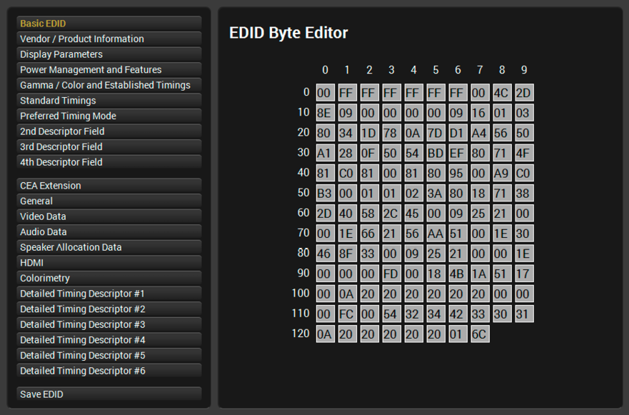
EDID Editor window
7.8.3. Creating an EDID - Easy EDID Creator

Since the Advanced EDID Editor mentioned above needs more detailed knowledge about EDID, Lightware introduced a wizard-like interface for fast and easy EDID creation. With Easy EDID Creator, it is possible to create custom EDIDs in four simple steps. By clicking on the Create button below the Source panel, Easy EDID Creator is opened in a new window.
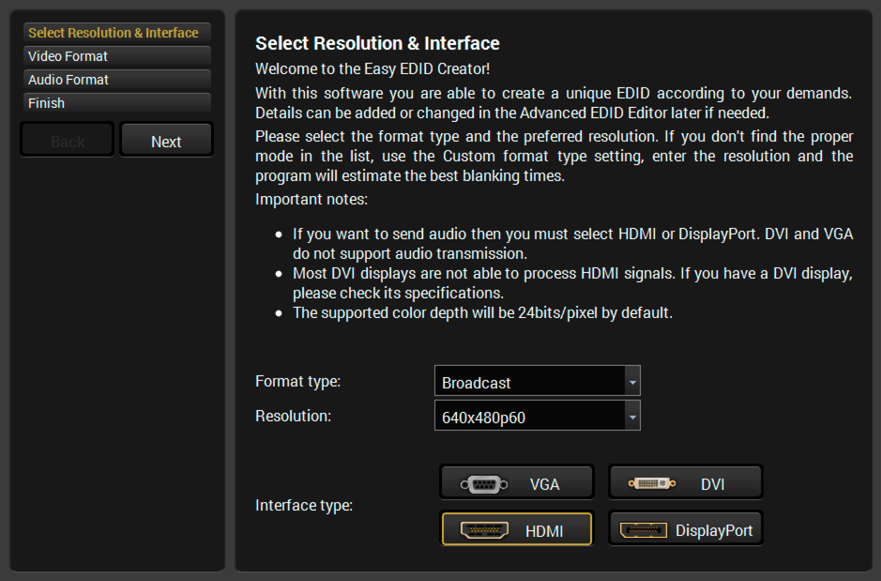
EDID Creator window
7.8.4. EDID Summary Window

Select an EDID from the Source panel and press the Info button to display the EDID summary.
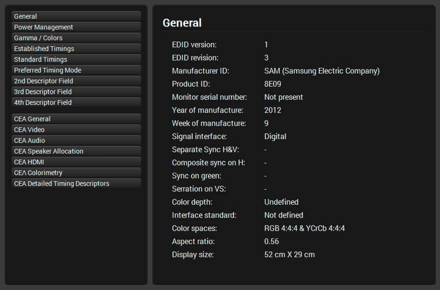
EDID summary window
The DisplayID is defined by a VESA standard created beside the EDID structure. The Advanced EDID editor gets a DisplayID section, where additional metadata is stored for the video sources about the display capabilities.
INFO:EDID has only 11 bits for active resolution dimensions, it means that the maximum pixel number is 4095.
DisplayID extension supports high resolution displays and tile mode. This interface provides easy and user-friendly input of the Display ID information. #displayid

EDID Editor Window

Settings menu - Overview tab
The most important hardware and software related information can be found on this tab: hardware and firmware version, serial numbers, endpoint statistics, temperatures, operation time, and voltage information. Device label can be changed to unique description. #firmwareversion #label #devicelabel #license #producttype #serialnumber
Licenses
MX2M-FR24R matrix switcher can be purchased with no PSU redundancy. In this case only one PSU drawer is installed with a power supply unit (Power Drawer 1, Primary), and the Single PSU License is installed on the matrix, which results in the Power Drawer 2 being unable to accept the second PSU drawer. Customers have the possibility of purchasing a code that makes the Single PSU License inactive. For more details, please contact sales@lightware.com.
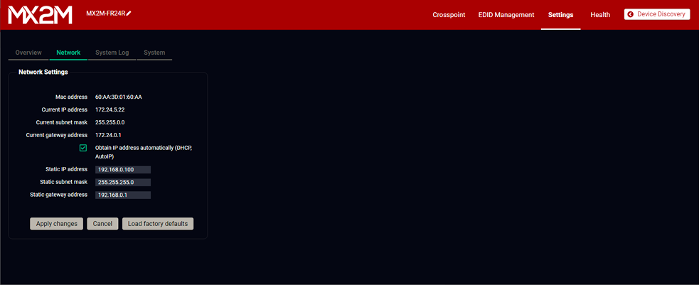
Settings menu - Network tab
Static IP address and DHCP (dynamic IP address) settings can be set on this tab. Always press the Apply settings button to save changes.
Factory default settings of the matrix can be recalled with a dedicated button. See the factory default values in the Factory Default Settings section. #network #dhcp #ipaddress
7.9.3. System Log

Settings menu - System Log tab
All matrix related notifications are listed in the System log tab, which are grouped into four categories: info, notice, warning, and error. The categories are summarized on the right side of the tab in the Summary section. The list can be customized with the Column Switchers by turning the following columns on or off: Time, Level, Identification, and Message.
All system log tracks can be saved to the control computer with the Export full system log button. #log
INFO:Please always download the system logs and send them to the Lightware Support Team (support@lightware.com) for the most effective collaboration in case of a troubleshooting issue.

Settings menu - System tab
The following functions are available under the System tab:
▪Date / time settings - system time can be set manually or can be synchronized with your control device. #time #date
▪Save and restore system settings #backup #restore
=Save system settings - clicking on the Save button saves the actual configuration of the matrix to a file.
=Restore - select a backup file of the matrix on your computer and select the Restore button to load it. The configuration settings saved in the file are applied immediately.
▪Load factory defaults - recalling factory default settings and values for the matrix. All factory default settings are listed in the Factory Default Settings section. #factory
▪Reboot device - the matrix switcher reboots, it is the same as disconnecting the power source and reconnecting it again. #reboot #restart #reset
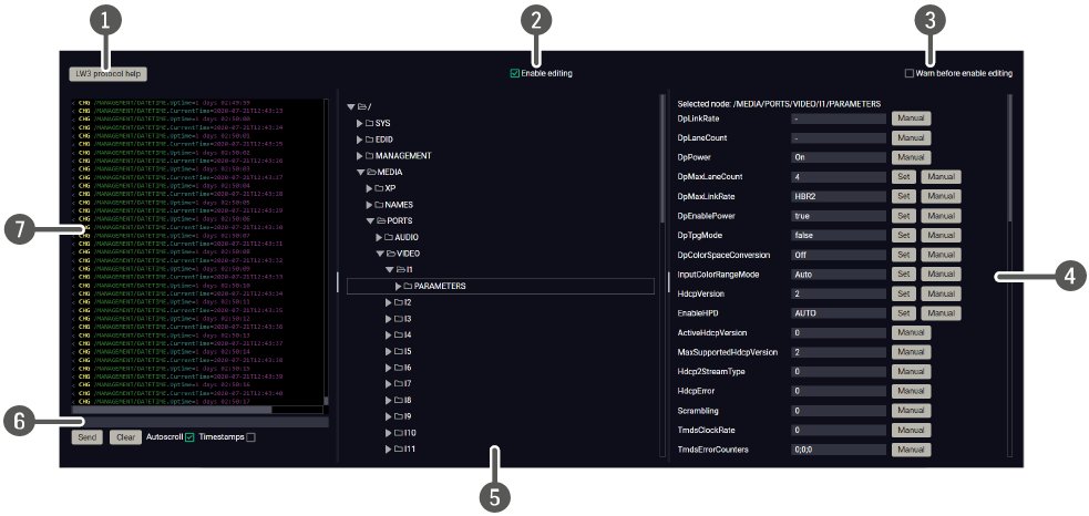
Select the Settings / Terminal menu to open the Terminal window. #terminal #advancedview
|
|
LW3 protocol help |
Pushing the button opens a help window that describes the most important information about LW3 protocol commands in HTML format. |
|
|
|
Edit mode |
The default appearance is the read-only mode. If you want to modify the values or parameters, tick the option. You will be prompted to confirm your selection. |
|
|
|
Warning mode |
If this box checked in, a warning window pops up when you enable Edit mode. |
|
|
|
Node list |
Correspondent parameters and nodes are shown that are connected to the selected item in the protocol tree. |
|
|
Manual button: |
Manual (short description) of the node can be called and displayed in the terminal window. |
||
|
Set button: |
Saves the value/parameter typed in the textbox. |
||
|
Call button: |
Calls the method, e.g. reloads factory default settings. |
||
|
|
Protocol tree |
LW3 protocol tree; select an item to see its content. |
|
|
|
Command line |
Type the desired command and execute it with the Send button. Clear all current commands and responses in the Terminal window by the Clear button. |
|
|
|
Terminal window |
Commands and responses with time and date are listed in this window. Sent commands start with ‘>’ character, received responses start with ‘<’ character. The color of each item depends on the type of the command and response. The content of the window can be emptied by the Clear button. If the Autoscroll option is ticked, the list is scrolled automatically when a new line is added. |
|


7.11.1. Overview
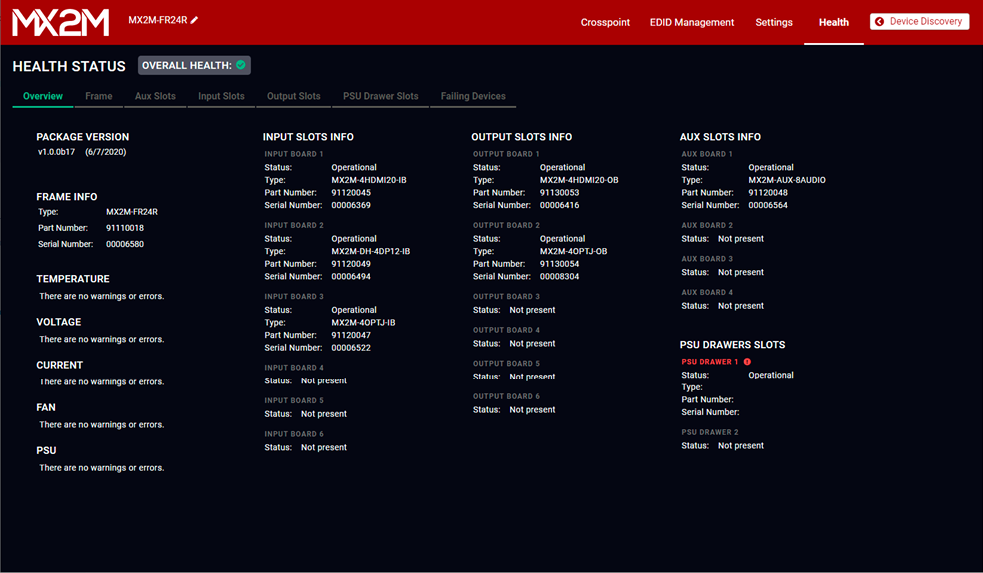
Health menu - Overview tab
All general information about the matrix frame and the installed I/O boards is available in the Overview tab of the Health menu. The firmware package version, error or warning messages, the list of installed I/O boards grouped by types and the serial and part numbers can be seen on this tab. #health #status #producttype
The Overall Health indicator shows whether there is any warning or error message in the system:
|
Icon |
Type |
Description |
|
|
OK |
No active warning or error level log entry exists for the system or a device seated in the system. |
|
|
Warning |
Active warning level log entry exists and no active error level log entry exists for the system or a device seated in the system. |
|
|
Error |
Active error level log entry exists for the system or a device seated in the system. |


#health #status #systemmonitor
7.11.2. Frame

Health menu - Frame tab
The most important information about the matrix frame is available on the Frame tab. The firmware package version, AC power line redundancy, frame voltages, frame temperatures and the fan speeds can be checked.
7.11.3. Aux Slots
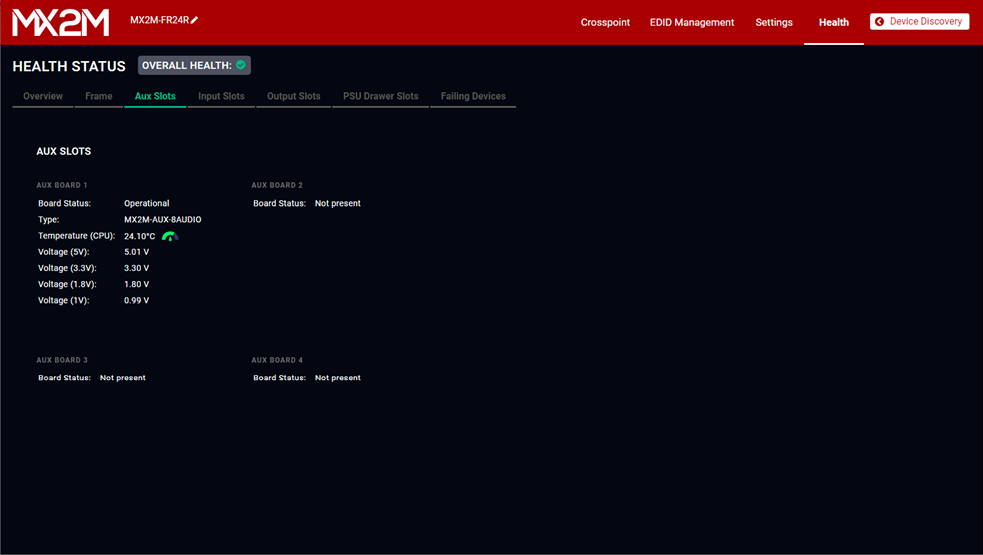
Health menu - Aux Slots tab
The most important information about the auxiliary boards grouped by the board slots is available on the Aux Slots tab. The type of the installed I/O board, the status of the board, the temperature and voltage information can be checked on the tab.
INFO:See the details about the location of the AUX board slots in the Layout of the Input/Output Board Slots and Power Drawer Slots section.
7.11.4. Input Slots

Health menu - Input Slots tab
The most important information about the input boards grouped by the board slots is available on the Input Slots tab. The type of the installed I/O board, the status of the board, the temperature and voltage information can be checked on the tab.
INFO:See the details about the location of the input board slots in the Layout of the Input/Output Board Slots and Power Drawer Slots section.
7.11.5. Output Slots
Health menu - Output Slots tab
The most important information about the output boards grouped by the board slots is available on the Output Slots tab. The type of the installed I/O board, the status of the board, the temperature and voltage information can be checked on the tab.
INFO:See the details about the location of the output board slots in the Layout of the Input/Output Board Slots and Power Drawer Slots section.
7.11.6. PSU Drawer Slots
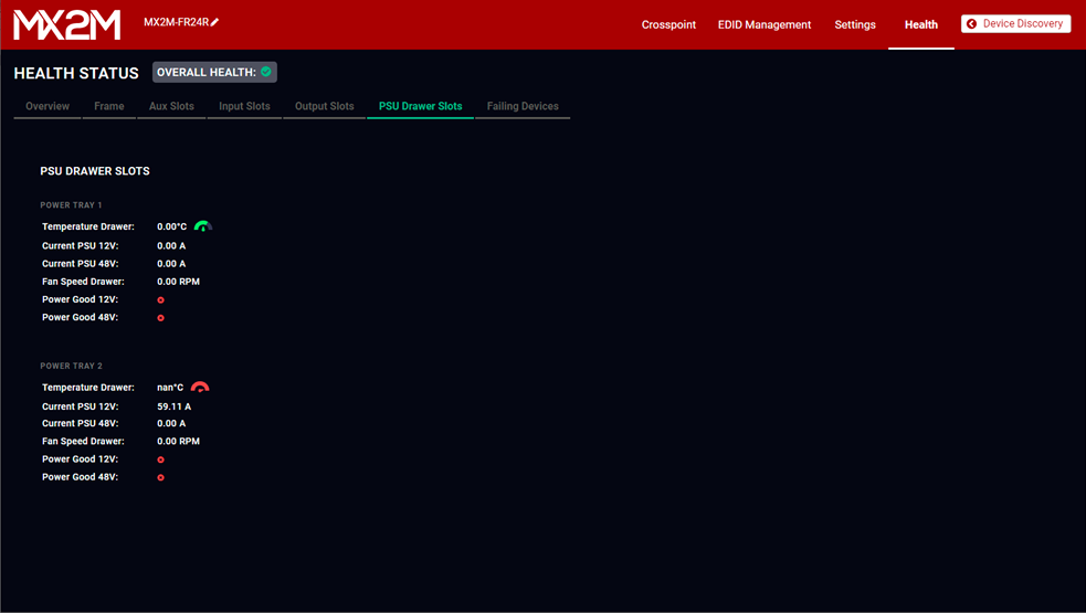
Health menu - PSU Drawer Slots tab
The most important information about the PSU drawers grouped by the power drawer slots is available on the PSU Drawer Slots tab. The temperature, current, voltage and fan speed information can be checked on the tab.
INFO:See the details about the numbering of the PSU drawer slots in the Layout of the Input/Output Board Slots and Power Drawer Slots section.
7.11.7. Failing Devices

Health menu - Failing Devices tab
The most important status information about the matrix frame and the installed I/O boards is available on the Failing Devices tab.
Overall Health Info about the I/O Board Slots
The indicators show whether there is any warning or error message is in the system:
|
Icon |
Type |
Description |
|
|
OK |
No active warning or error level log entry exists for the system or a device seated in the system. |
|
|
Warning |
Active warning level log entry exists and no active error level log entry exists for the system or a device seated in the system. |
|
|
Error |
Active error level log entry exists for the system or a device seated in the system. |
Matrix Drawing
The drawing of the matrix shows the recent installation of the matrix frame, including the I/O boards with the slots where they are installed.
The device can be controlled through Lightware 3 (LW3) protocol commands to ensure compatibility with other Lightware products. The supported LW3 commands are described in this chapter.
8.1. Overview
The Lightware Protocol #3 (LW3) is implemented in almost all new Lightware devices (matrix switchers, signal extenders and distribution amplifiers) since 2012. The protocol is ASCII-based and all commands are terminated with a carriage return (Cr, ‘\r’) and line feed (Lf, ‘\n’) pair. It is organized as a tree structure that provides outstanding flexibility and user-friendly handling with ‘nodes’, ‘properties’ and ‘methods’. The Advanced View of the Lightware Device Controller software is the perfect tool for browsing and learning how the LW3 protocol can be used in practice.
8.2. Instructions for the Terminal Application Usage

Terminal Application
The LW3 protocol commands can be applied to the receiver using a terminal application. You need to install one of them on your control device, for example Putty or CLI. #terminal
Establishing Connection
Follow the steps for establishing connection to the receiver:
Step 1.Connect the receiver to a LAN over Ethernet (see the details in the Connecting Steps section).
Step 2.Open the terminal application (e.g. Putty).
Step 3.Add the IP address of the device (the default IP setting is the DHCP (dynamic IP address)) and the port number (6107).
Step 4.Select the Raw connection type, and open the connection.
Once the terminal window is opened, you can enter the LW3 protocol commands, which are listed in the following sections.

LW3 protocol command communication in a terminal window
8.3. Protocol Rules
8.3.1. LW3 Tree Structure and Command Structure (examples)

8.3.2. General Rules
▪All names and parameters are case-sensitive.
▪The nodes are separated by a slash (‘/’) character.
▪The node name can contain the elements of the English alphabet and numbers.
▪Use the TCP port no. 6107 when using LW3 protocol over Ethernet.
▪When a command is issued by the device, the received response cannot be processed by the CPU.
▪The node paths describe the exact location of the node, listing each parent node up to the root.
8.3.3. Command Types
GET command
The GET command can be used to get the child nodes, properties and methods of a specific node. It can also be used to get the value of a property. Use the dot character (.) when addressing a property:
»GET /.SerialNumber
«pr /.SerialNumber=87654321
GETALL command
The GETALL command can be used to get all child nodes, properties and methods of a node with one command.
»GETALL /MEDIA/XP
«n- /MEDIA/XP/VIDEO
«n- /MEDIA/XP/AUDIO
«m- /MEDIA/XP:MultiLayer_Connect
«m- /MEDIA/XP:MultiLayer_Switch
«m- /MEDIA/XP:MultiLayer_SwitchAll
«m- /MEDIA/XP:MultiLayer_SwitchMulti
SET command
The SET command can be used to modify the value of a property. Use the dot character (.) when addressing the property:
»SET /MEDIA/PORTS/VIDEO/I1/PARAMETERS.HdcpVersion=2
«pw /MEDIA/PORTS/VIDEO/I1/PARAMETERS.HdcpVersion=2
CALL command
A method can be invoked by the CALL command. Use the colon character (:) when addressing the method:
»CALL /EDID:switchAll(F147)
«mO /EDID:switchAll
MAN command
The manual is a human readable text that describes the syntax and provides a hint on how to use the primitives. For every node, property and method in the tree there is a manual; type the MAN command to get the manual:
»MAN /MEDIA/PORTS/VIDEO/O1/PARAMETERS.AudioSource
«pm /MEDIA/PORTS/VIDEO/O1/PARAMETERS.AudioSource ["Hdmi" | "AudioLayer" | "Off"] Sets the source of the embedded audio stream
8.3.4. Prefix Summary
DEFINITION:The prefix is a 2-character-long code that describes the type of the response.
The following prefixes are defined in the LW3 protocol:
|
Prefix |
Description |
Prefix |
Description |
|
|
n- |
a node |
pm |
a manual for the property |
|
|
nE |
an error for a node |
m- |
a method |
|
|
nm |
a manual for a node |
mO |
a response after a successful method execution |
|
|
pr |
a read-only property |
mF |
a response after a failed method execution |
|
|
pw |
read-write property |
mE |
an error for a method |
|
|
pE |
an error for the property |
mm |
a manual for a method |
8.3.5. Error Messages
There are several error messages defined in the LW3 protocol, all of them have a unique error number.
»CALL /MEDIA/XP/VIDEO:lockSource(IA)
«mE /MEDIA/XP/VIDEO:lockSource %E006: Illegal operation
DEFINITION:An escape sequence is a sequence of characters that does not represent itself when used inside a character or string literal, but is translated into another character or a sequence of characters.
Property values and method parameters can contain characters that are used as control characters in the protocol. They must be escaped. The escape character is the backslash (‘\’), and escaping means injecting a backslash before the character that should be escaped (like in C language).
Control characters are the following: \ { } # % ( ) \r \n \t
8.3.7. Signature
DEFINITION:The signature is a four-digit-long hexadecimal value that can be optionally placed before every command to keep a command and the corresponding responses together as a group.
Each line is terminated with carriage return (Cr, ‘\r’) and line feed (Lf, ‘\n’) characters. In several cases the number of the lines in the response cannot be determined in advance, e.g. the client intends to receive the whole response and also wants to be sure that the received lines belong together and to the same command. In these cases, a special feature, the ‘signature’ can be used. The response to that particular command will also be preceded by the signature, and the corresponding lines will be between brackets:
»1700#GET /EDID.*
«{1700
«pr /EDID.EdidStatus=F149;F149;F149;F149;F149;F149;F149;F149;F149;F149; F149;F149;F149;F149;F149; F149;F149;F149;F149;F149;F149;F149;F149;F149;
«pr /EDID.Features=DisplayID;
«m- /EDID:copy
«m- /EDID:delete
«m- /EDID:reset
«m- /EDID:switch
«m- /EDID:switchAll
«}
INFO:The lines of the signature are also Cr and Lf terminated.
8.3.8. Subscription
DEFINITION:Subscription to a node means that the user will get a notification if a property of the node changes.
A user can subscribe to any node. These notifications are asynchronous messages and are useful to keep the client application up to date, without having to periodically poll the node to detect a changed property. When the user does not want to be informed about the changes anymore, he can simply unsubscribe from the node.
ATTENTION!The subscriptions are handled separately for connections. Hence, if the connection is terminated, all registered subscriptions are deleted. After reopening a connection all subscribe commands have to be sent in order to get the notifications of the changes on that connection.
Subscribe to a Node
»OPEN /MEDIA/VIDEO
«o- /MEDIA/VIDEO
Subscribe to Multiple Nodes
»OPEN /MEDIA/VIDEO/*
«o- /MEDIA/VIDEO/*
Unsubscribe from a Node
»CLOSE /MEDIA/VIDEO
«c- /MEDIA/VIDEO
Get the Active Subscriptions
»OPEN
«o- /MEDIA/VIDEO
«o- /EDID
«o- /DISCOVERY
Unsubscribe from Multiple Nodes
»CLOSE /MEDIA/VIDEO/*
«c- /MEDIA/VIDEO/*
8.3.9. Notifications about the Changes of the Properties
When the value of a property is changed and the user is subscribed to the node that the property belongs to, an asynchronous notification is generated. This notification is called the ‘change message’. The format of such a message is very similar to the response for the GET command:
«CHG /SYS/UPDATE.NumberOfBoardsSeated=6
A Short Example of How to Use the Subscription
There are two independent users controlling the device through two independent connections (Connection #1 and Connection #2). The events in the rows occur after each other.
|
»OPEN /MEDIA/PORTS/VIDEO/O1/PARAMETERS «o- /MEDIA/PORTS/VIDEO/O1/PARAMETERS »GET /MEDIA/PORTS/VIDEO/O1/PARAMETERS.ColorSpaceSetting «pw /MEDIA/PORTS/VIDEO/O1/PARAMETERS.ColorSpaceSetting=1 |
connection #1 |
|
»GET /MEDIA/PORTS/VIDEO/O1/PARAMETERS.ColorSpaceSetting «pw /MEDIA/PORTS/VIDEO/O1/PARAMETERS.ColorSpaceSetting=1 »SET /MEDIA/PORTS/VIDEO/O1/PARAMETERS.ColorSpaceSetting=2 «pw /MEDIA/PORTS/VIDEO/O1/PARAMETERS.ColorSpaceSetting=2 |
connection #2 |
|
«CHG /MEDIA/PORTS/VIDEO/O1/PARAMETERS.ColorSpaceSetting=2 |
connection #1 |
Explanation: The first user (Connection #1) set a subscription to a node. Later the other user (Connection #2) made a change, and thanks to the subscription, the first user got a notification about the change.
8.3.10. Legend for the Control Commands
|
Format |
Description |
|
<in> |
Input port number |
|
<out> |
Output port number |
|
<port> |
Input or output port number |
|
<loc> |
Location number |
|
<parameter> |
Variable, which is defined and described in the command |
|
<expression> |
Batched parameters: the underline means that more expressions or parameters can be placed by using a semicolon, e.g. O1;O2 or F27:U1;F147:U2 |
|
|
Sent command |
|
|
Received response |
|
· |
Space character |


8.4. System Commands
8.4.1. Querying the Product Name
The name of the product is a read-only parameter and cannot be modified.
Command and Response #producttype
»GET·/.ProductName
«pr·/.ProductName=<Product_name>
Example
»GET /.ProductName
«pr /.ProductName=MX2M-FR24R
8.4.2. Setting the Device Label
INFO:The device label can be changed to a custom text in the Overview tab of the LDC software. This writable parameter is not the same as the ProductName parameter.
Command and Response #devicelabel #label
»SET·/MANAGEMENT/LABEL/DeviceLabel=<Custom_name>
«pw·/MANAGEMENT/LABEL/DeviceLabel=<Custom_name>
The Device Label can be 39 characters long and ASCII characters are allowed. Longer names are truncated.
Example
»SET /MANAGEMENT/LABEL.DeviceLabel=MX2M_Conference
«pw /MANAGEMENT/LABEL.DeviceLabel=MX2M_Conference
8.4.3. Querying the Serial Number
Command and Response #serialnumber
»GET·/.SerialNumber
«pr·/.SerialNumber=<serial_number>
Example
»GET /.SerialNumber
«pr /.SerialNumber=87654321
8.4.4. Querying the Firmware Version
Command and Response #firmwareversion
»GET·/MANAGEMENT/UID/PACKAGE.Version
«pr·/MANAGEMENT/UID/PACKAGE.Version=<firmware_version>
Example
»GET /MANAGEMENT/UID/PACKAGE.Version
«pr /MANAGEMENT/UID/PACKAGE.Version=1.0.0b20
8.4.5. Querying the Date and Time of the System
The query returns with the current date and time that is set in the matrix. The format is based on the ISO 8601 standard.
Command and Response #time #date
»GET·/MANAGEMENT/DATETIME.CurrentTime
«pr·/MANAGEMENT/DATETIME.CurrentTime=<date_time>
Parameters
|
Parameter |
Description |
Formula |
|
<date_time> |
Current date and time |
YYYY-MM-DDTHH:MM:SS |
Example
»GET /MANAGEMENT/DATETIME.CurrentTime
«pr /MANAGEMENT/DATETIME.CurrentTime=2020-09-01T17:38:37
8.4.6. Setting the Date and Time Manually
The date and time format is based on the ISO 8601 standard.
Command and Response
»CALL·/MANAGEMENT/DATETIME:setTime=<date_time>
«mO·/MANAGEMENT/DATETIME:setTime=
Parameters
|
Parameter |
Description |
Formula |
|
<date_time> |
Current date and time |
YYYY-MM-DDTHH:MM:SS |
Example
»CALL /MANAGEMENT/DATETIME:setTime=2020-12-24T20:00:15
«mO /MANAGEMENT/DATETIME.setTime=
8.4.7. Setting the Brightness of the LCD Screen
Command and Response
»SET·/SYS/CECU/LCD.Brightness=<parameter>
«pw·/SYS/CECU/LCD.Brightness=<parameter>
Parameters
The <parameter> of display brightness can be set between values 0 and 10.
Example
»SET /SYS/CECU/LCD.Brightness=5
«pw /SYS/CECU/LCD.Brightness=5
8.4.8. Control Lock of the LCD Menu
Enable/disable the operation of the jog dial control knob and the LCD menu control.
Command and Response #controllock
»SET·/SYS/CECU/LCD.ControlLock=<logical_value>
«pw·/SYS/CECU/LCD.ControlLock=<logical_value>
Parameters
|
Identifier |
Parameter description |
Value |
Value description |
|
<mode> |
Control lock mode |
true |
Enabled |
|
false |
Disabled |
Example
»SET /SYS/CECU/LCD.ControlLock=true
«pw /SYS/CECU/LCD.ControlLock=true
Command and Response #license
»CALL·/MANAGEMENT/LICENSE:addLicense()
«mO·/MANAGEMENT/LICENSE:addLicense=
Example
»CALL /MANAGEMENT/LICENSE:addLicense()
«mO /MANAGEMENT/LICENSE:addLicense=
Command and Response #license
»CALL·/MANAGEMENT/LICENSE:removeLicense()
«mO·/MANAGEMENT/LICENSE:removeLicense=
Example
»CALL /MANAGEMENT/LICENSE:removeLicense()
«mO /MANAGEMENT/LICENSE:removeLicense=
8.4.11. Software Resetting the Device
The core application of the matrix can be restarted.
Command and Response #softreset
»CALL·/SYS:softReset()
«mO·/SYS:softReset=
Example
»CALL /SYS:softReset()
«mO /SYS:softReset=
The matrix switcher can be restarted – the current connections and the AV signal transmission will be terminated.
Command and Response #restart #reboot #reset
»CALL·/SYS:reset()
«mO·/SYS:reset=
Example
»CALL /SYS:reset()
«mO /SYS:reset=
8.4.13. Restoring the Factory Default Settings
Command and Response #factory
»CALL·/SYS:factoryDefaults()
«mO·/SYS:factoryDefaults=
Example
»CALL /SYS:factoryDefaults()
«mO /SYS:factoryDefaults=
The device is restarted, current connections are terminated, and the default settings are restored. See the complete list in the Factory Default Settings section.
8.5. I/O Board Management
8.5.1. Querying the Status of a Board
The query returns the actual status of the selected I/O board in the matrix frame.
Command and Response
»GET·/SYS/<board>.Status
«pr·/SYS/<board>.Status=<status>
Parameters
|
Identifier |
Parameter description |
Value |
Value description |
|
<board> |
The identifier of the board. |
IB1...IB6 |
Input board ID, the values can be IB1, IB2, IB3, IB4, IB5 or IB6. |
|
OB1...OB6 |
Output board ID, the values can be OB1, OB2, OB3, OB4, OB5 or OB6. |
||
|
LS1...LS4 |
Auxiliary (LS - Low Speed) board ID, the values can be LS1, LS2, LS3, or LS4. |
||
|
<status> |
Current status of the I/O board |
No power |
Board is present but not powered. |
|
Not present |
Board is not present. |
||
|
Seated |
Board is seated into the slot. |
||
|
Connecting |
Connecting to the CPU. |
||
|
Connected |
Connected to the CPU but not initialized yet. |
||
|
Initializing |
Under initialization. |
||
|
Operational |
Board is operational and ready for use. |
||
|
Reset |
Board is rebooting. |
||
|
Debug |
Board is in debug mode. |
||
|
FirmwareUpgradeEthernet |
The firmware of the board is being updated by the matrix frame. |
||
|
BootloadMode |
Board is in bootload (firmware update) mode, which might happen after an unsuccesful fimrware update procedure. Restarting the firmware update procedure is recommended. |
||
|
InWrongSlot |
The board is seated to the wrong slot. See the layout of the I/O board slot in the Board Installation and Handling section. |
||
|
Unknown |
The status of board is unknown. Reseating of the board is recommended. |
Example
»GET /SYS/OB1.Status
«pr /SYS/OB1.Status=Operational
8.5.2. Querying the Number of Seated I/O Boards
The query returns the number of the seated I/O boards in the matrix frame, including IB, OB, and AUX (Low Speed) boards.
Command and Response
»GET·/SYS/UPDATE.NumberOfBoards
«pr·/SYS/UPDATE.NumberOfBoards=<number>
Example
»GET /SYS/UPDATE.NumberOfBoards
«pr /SYS/UPDATE.NumberOfBoards=7
8.5.3. Querying the List of Seated I/O Boards
The query returns the list of the seated I/O boards in the matrix frame, including IB, OB, and AUX (Low Speed) boards.
Command and Response
»GET·/SYS/UPDATE.BoardsInSeatedState
«pr·/SYS/UPDATE.BoardsInSeatedState=<board_slot1>;<board_slot2>;...<board_slotX>
Example
»GET /SYS/UPDATE.BoardsInSeatedState
«pr /SYS/UPDATE.BoardsInSeatedState=LS1;LS2;IB2;IB4;OB1;OB2;OB3;OB4;OB5
8.5.4. Querying the List of Operational I/O Boards
The query returns the list of the operational I/O boards in the matrix frame, including IB, OB, and AUX (Low Speed) boards.
Command and Response
»GET·/SYS/UPDATE.BoardsInOperationalState
«pr·/SYS/UPDATE.BoardsInOperationalState=<board_slot1>;<board_slot2>;...<board_slotX>
Example
»GET /SYS/UPDATE.BoardsInOperationalState
«pr /SYS/UPDATE.BoardsInOperationalState=LS1;LS2;IB2;IB4;OB1;OB2;OB3;OB4;OB5
8.5.5. Querying the List of Failed I/O Boards
The query returns the list of the failed I/O boards in the matrix frame, including IB, OB, and AUX (Low Speed) boards.
Command and Response
»GET·/SYS/UPDATE.BoardsInErrorState
«pr·/SYS/UPDATE.BoardsInErrorState=<board_slot1>;<board_slot2>;...<board_slotX>
Example
»GET /SYS/UPDATE.BoardsInErrorState
«pr /SYS/UPDATE.BoardsInErrorState=LS1;LS2;IB2;IB4;OB1;OB2;OB3;OB4;OB5
8.5.6. Querying the Product Name of the I/O Board
The name of the product is a read-only parameter and cannot be modified.
Command and Response #producttype
»GET·/SYS/<board>.ProductName
«pr·/SYS/<board>.ProductName=<Product_name>
Example
»GET /SYS/IB1.ProductName
«pr /SYS/IB1.ProductName=MX2M-4HDMI20-IB
8.5.7. Querying the Serial Number of the I/O Board
Command and Response #serialnumber
»GET·/SYS/<board>.SerialNumber
«pr·/SYS/<board>.SerialNumber=<serial_number>
Example
»GET /SYS/LS1.SerialNumber
«pr /SYS/LS1.SerialNumber=87654321
8.5.8. Querying the Firmware Version of the I/O Board
Command and Response #firmwareversion
»GET·/SYS/<board>.PackageVersion
«pr·/SYS/<board>.PackageVersion=<firmware_version>
Example
»GET /SYS/OB1.PackageVersion
«pr /SYS/OB1.PackageVersion=1.0.0b20
8.5.9. Rebooting the I/O Board
The I/O board can be restarted – the current connections and the AV signal transmission will be terminated.
Command and Response #restart #reboot #reset
»CALL·/SYS/<board>:reset()
«mO·/SYS/<board>:reset=
Example
»CALL /SYS/IB1:reset()
«mO /SYS/IB1:reset=
8.6. Video Switching and Crosspoint Settings
8.6.1. Querying the Video Crosspoint State
Command and Response
»GET·/MEDIA/XP/VIDEO.DestinationConnectionStatus
«pr·/MEDIA/XP/VIDEO.DestinationConnectionStatus=<out1_state>;<out2_state>;...;<out24_state>
Parameters
The <out#_state> parameters mean the output ports (O1, O2 etc.) one after the other. The value of the parameter shows the input port switched to the given output port.
Example
»GET /MEDIA/XP/VIDEO.DestinationConnectionStatus
«pr /MEDIA/XP/VIDEO.DestinationConnectionStatus=I1;I1;I1;I1;I1;I1;I1;I1;I1;I1;I1;I1;I1;I1;I1;I1;I1;I1;I1;I1;I1;I1;I1;I1;
I1 input port is connected to all output ports.
8.6.2. Switching an Input to an Output
Command and Response #switch #crosspoint
»CALL·/MEDIA/XP/VIDEO:switch(<in>:<out>)
«mO·/MEDIA/XP/VIDEO:switch=
Example
»CALL /MEDIA/XP/VIDEO:switch(I4:O1)
«mO /MEDIA/XP/VIDEO:switch=
8.6.3. Disconnecting the Output from any Input
Command and Response
»CALL·/MEDIA/XP/VIDEO:switch(0:<out>)
«mO·/MEDIA/XP/VIDEO:switch=
Example
»CALL /MEDIA/XP/VIDEO:switch(0:O1)
«mO /MEDIA/XP/VIDEO:switch=
8.6.4. Switching an Input to All Outputs
Command and Response
»CALL·/MEDIA/XP/VIDEO:switchAll(<in>)
«mO·/MEDIA/XP/VIDEO:switchAll=
Example
»CALL /MEDIA/XP/VIDEO:switchAll(I1)
«mO /MEDIA/XP/VIDEO:switchAll=
TIPS AND TRICKS:All output ports can be disconnected with the '0' value:
CALL /MEDIA/XP/VIDEO:switchAll(0).
8.6.5. Multiple Switching
The whole crosspoint can be set by sending one command as follows.
Command and Response
»CALL·/MEDIA/XP/VIDEO:switchMulti(<out1_source>;<out2_source>;...;<out8_source>)
«mO·/MEDIA/XP/VIDEO:switchMulti=
The source is not required to be set on all output ports (see the Example2).
Parameters
The <out#_source> parameters mean the output ports one after the other. The value of the parameter shows the input port switched to the given output port.
Example1
»CALL /MEDIA/XP/VIDEO:switchMulti(I1;I2;I3;I4;I5;I6;I7;I8)
«mO /MEDIA/XP/VIDEO:switchMulti=
Example2
»CALL /MEDIA/XP/VIDEO:switchMulti(I1;I2;;;I5)
«mO /MEDIA/XP/VIDEO:switchMulti=
8.6.6. Muting a Video Input
Command and Response #mute
»CALL·/MEDIA/XP/VIDEO:muteSource(<in>)
«mO·/MEDIA/XP/VIDEO:muteSource=
Example
»CALL /MEDIA/XP/VIDEO:muteSource(I1)
«mO /MEDIA/XP/VIDEO:muteSource=
Command and Response #unmute
»CALL·/MEDIA/XP/VIDEO:unmuteSource(<in>)
«mO·/MEDIA/XP/VIDEO:unmuteSource=
Example
»CALL /MEDIA/XP/VIDEO:unmuteSource(I1;I3)
«mO /MEDIA/XP/VIDEO:unmuteSource=
Command and Response #lock
»CALL·/MEDIA/XP/VIDEO:lockSource(<in>)
«mO·/MEDIA/XP/VIDEO:lockSource=
Example
»CALL /MEDIA/XP/VIDEO:lockSource(I1;I2;I3)
«mO /MEDIA/XP/VIDEO:lockSource=
8.6.9. Unlocking a Video Input
Command and Response #unlock
»CALL·/MEDIA/XP/VIDEO:unlockSource(<in>)
«mO·/MEDIA/XP/VIDEO:unlockSource=
Example
»CALL /MEDIA/XP/VIDEO:unlockSource(I1;I3)
«mO /MEDIA/XP/VIDEO:unlockSource=
Command and Response #mute
»CALL·/MEDIA/XP/VIDEO:muteDestination(<out>)
«mO·/MEDIA/XP/VIDEO:muteDestination=
Example
»CALL /MEDIA/XP/VIDEO:muteDestination(O1;O3)
«mO /MEDIA/XP/VIDEO:muteDestination=
8.6.11. Unmuting a Video Output
Command and Response #unmute
»CALL·/MEDIA/XP/VIDEO:unmuteDestination(<out>)
«mO·/MEDIA/XP/VIDEO:unmuteDestination=
Example
»CALL /MEDIA/XP/VIDEO:unmuteDestination(O1;O2)
«mO /MEDIA/XP/VIDEO:unmuteDestination=
8.6.12. Locking a Video Output
Command and Response #lock
»CALL·/MEDIA/XP/VIDEO:lockDestination(<out>)
«mO·/MEDIA/XP/VIDEO:lockDestination=
Example
»CALL /MEDIA/XP/VIDEO:lockDestination(O1;O4)
«mO /MEDIA/XP/VIDEO:lockDestination=
8.6.13. Unlocking a Video Output
Command and Response #unlock
»CALL·/MEDIA/XP/VIDEO:unlockDestination(<out>)
«mO·/MEDIA/XP/VIDEO:unlockDestination=
Example
»CALL /MEDIA/XP/VIDEO:unlockDestination(O1;O2;O4)
«mO /MEDIA/XP/VIDEO:unlockDestination=
8.7. Audio Switching and Crosspoint Settings
8.7.1. Querying the Audio Crosspoint State
Command and Response
»GET·/MEDIA/XP/AUDIO.DestinationConnectionStatus
«pr·/MEDIA/XP/AUDIO.DestinationConnectionStatus=<out1_state>;<out2_state>;...;<out24_state>
Parameters
The <out#_state> parameters mean the output ports (O1, O2 etc.) one after the other. The value of the parameter shows the input port switched to the given output port.
Example
»GET /MEDIA/XP/AUDIO.DestinationConnectionStatus
«pr /MEDIA/XP/AUDIO.DestinationConnectionStatus=I2;I2;I2;I2;I2;I2;I2;I2;I2;I2;I2;I2;I2;I2;I2;I2;I2;I2;I2;I2;I2; I2;I2;I2;I2;I2;I2;I2;I2;I2;I2;I2;I2;I2;I2;I2;I2;I2;I2;I2;I2;I2;I2;I2;I2;I2;I2;I2;I2;I2;I2;I2;I2;I2;I2;I2;I2;I2;I2;I2;I2;I2;I2;I2; I2;I2;I2;I2;I2;I2;I2;I2;I2;I2;I2;I2;I2;I2;I2;I2;I2;I2;I2;I2;I2;I2;I2;I2;
I2 input port is connected to all output ports.
8.7.2. Switching an Input to an Output
Command and Response #switch #crosspoint
»CALL·/MEDIA/XP/AUDIO:switch(<in>:<out>)
«mO·/MEDIA/XP/AUDIO:switch=
Example
»CALL /MEDIA/XP/AUDIO:switch(I4:O1)
«mO /MEDIA/XP/AUDIO:switch=
8.7.3. Disconnecting the Output from any Input
Command and Response
»CALL·/MEDIA/XP/AUDIO:switch(0:<out>)
«mO·/MEDIA/XP/AUDIO:switch=
Example
»CALL /MEDIA/XP/AUDIO:switch(0:O1)
«mO /MEDIA/XP/AUDIO:switch=
8.7.4. Switching an Input to All Outputs
Command and Response
»CALL·/MEDIA/XP/AUDIO:switchAll(<in>)
«mO·/MEDIA/XP/AUDIO:switchAll=
Example
»CALL /MEDIA/XP/AUDIO:switchAll(I1)
«mO /MEDIA/XP/AUDIO:switchAll=
TIPS AND TRICKS:All output ports can be disconnected with the '0' value:
» CALL /MEDIA/XP/AUDIO:switchAll(0).
8.7.5. Multiple Switching
The whole crosspoint can be set by sending one command as follows. #switch #crosspoint
Command and Response
»CALL·/MEDIA/XP/AUDIO:switchMulti(<out1_source>;<out2_source>;...;<out8_source>)
«mO·/MEDIA/XP/AUDIO:switchMulti=
The source is not required to be set on all output ports (see the Example2).
Parameters
The <out#_source> parameters mean the output ports one after the other. The value of the parameter shows the input port switched to the given output port.
Example1
»CALL /MEDIA/XP/AUDIO:switchMulti(I1;I2;I3;I4;I5;I6;I7;I8)
«mO /MEDIA/XP/AUDIO:switchMulti=
Example2
»CALL /MEDIA/XP/AUDIO:switchMulti(I1;I2;;;I5)
«mO /MEDIA/XP/AUDIO:switchMulti=
The embedded/transmitted audio signal can be 2-channel LPCM or compressed (non-HBR) audio signal only. There are two possibilities in case of audio signal embedding/transmitting:
▪If the selected signal is of type LPCM, the user can select the two channels to be transmitted.
▪If the selected signal is compressed (non-HBR) audio, it can be embedded into the video stream without any further action.
Command and Response #channelmapping #mapping
»SET·/MEDIA/PORTS/AUDIO/<out>/PARAMETERS.MainOutputChannels=<left_channel>;<right_channel>
«pw·/MEDIA/PORTS/AUDIO/<out>/PARAMETERS.MainOutputChannels=<left_channel>;<right_channel>
Parameters
|
Identifier |
Parameter description |
Value |
Value description |
|
<left_channel> |
Selected channels are transmitted to the left and right channels of the output port |
1...8 |
Channel number |
|
<right_channel> |
Example
»SET /MEDIA/PORTS/AUDIO/O26/PARAMETERS.MainOutputChannels=1;2
«pw /MEDIA/PORTS/AUDIO/O26/PARAMETERS.MainOutputChannels=1;2
Command and Response #mute
»CALL·/MEDIA/XP/AUDIO:muteSource(<in>)
«mO·/MEDIA/XP/AUDIO:muteSource=
Example
»CALL /MEDIA/XP/AUDIO:muteSource(I1)
«mO /MEDIA/XP/AUDIO:muteSource=
8.7.8. Unmuting an Audio Input
Command and Response #unmute
»CALL·/MEDIA/XP/AUDIO:unmuteSource(<in>)
«mO·/MEDIA/XP/AUDIO:unmuteSource=
Example
»CALL /MEDIA/XP/AUDIO:unmuteSource(I1;I3)
«mO /MEDIA/XP/AUDIO:unmuteSource=
Command and Response #lock
»CALL·/MEDIA/XP/AUDIO:lockSource(<in>)
«mO·/MEDIA/XP/AUDIO:lockSource=
Example
»CALL /MEDIA/XP/AUDIO:lockSource(I1;I2;I3)
«mO /MEDIA/XP/AUDIO:lockSource=
8.7.10. Unlocking an Audio Input
Command and Response #unlock
»CALL·/MEDIA/XP/AUDIO:unlockSource(<in>)
«mO·/MEDIA/XP/AUDIO:unlockSource=
Example
»CALL /MEDIA/XP/AUDIO:unlockSource(I1;I3)
«mO /MEDIA/XP/AUDIO:unlockSource=
8.7.11. Muting an Audio Output
Command and Response #mute
»CALL·/MEDIA/XP/AUDIO:muteDestination(<out>)
«mO·/MEDIA/XP/AUDIO:muteDestination=
Example
»CALL /MEDIA/XP/AUDIO:muteDestination(O1;O3)
«mO /MEDIA/XP/AUDIO:muteDestination=
8.7.12. Unmuting an Audio Output
Command and Response #unmute
»CALL·/MEDIA/XP/AUDIO:unmuteDestination(<out>)
«mO·/MEDIA/XP/AUDIO:unmuteDestination=
Example
»CALL /MEDIA/XP/AUDIO:unmuteDestination(O1;O2)
«mO /MEDIA/XP/AUDIO:unmuteDestination=
8.7.13. Locking an Audio Output
Command and Response #lock
»CALL·/MEDIA/XP/AUDIO:lockDestination(<out>)
«mO·/MEDIA/XP/AUDIO:lockDestination=
Example
»CALL /MEDIA/XP/AUDIO:lockDestination(O1;O4)
«mO /MEDIA/XP/AUDIO:lockDestination=
8.7.14. Unlocking an Audio Output
Command and Response #unlock
»CALL·/MEDIA/XP/AUDIO:unlockDestination(<out>)
«mO·/MEDIA/XP/AUDIO:unlockDestination=
Example
»CALL /MEDIA/XP/AUDIO:unlockDestination(O1;O2;O4)
«mO /MEDIA/XP/AUDIO:unlockDestination=
8.8. Video Source Port Settings - HDMI / OPTJ
The following settings are valid only for the following input boards: #hdmi #optj
▪MX2M-4HDMI20-IB
▪MX2M-4OPTJ-IB
This setting allows sending non-encrypted content to a non-HDCP compliant display. See more information in the HDCP Management section.
Command and Response #hdcp
»SET·/MEDIA/PORTS/VIDEO/<in>/PARAMETERS.HdcpVersion=<number>
«pw·/MEDIA/PORTS/VIDEO/<in>/PARAMETERS.HdcpVersion=<number>
Parameters
|
Identifier |
Parameter description |
Value |
Value description |
|
<number> |
The setting sets the maximum enabled HDCP level |
0 |
HDCP-encryption is disabled. |
|
1 |
Encryption level is HDCP 1.4 |
||
|
2 |
Encryption level is HDCP 2.2 |
Example
»SET /MEDIA/PORTS/VIDEO/I1/PARAMETERS.HdcpVersion=2
«pw /MEDIA/PORTS/VIDEO/I1/PARAMETERS.HdcpVersion=2
8.8.2. Setting the Color Range
Command and Response #colorrange
»SET·/MEDIA/PORTS/VIDEO/<in>/PARAMETERS.InputColorRangeMode=<colorrange>
«pw·/MEDIA/PORTS/VIDEO/<in>/PARAMETERS.InputColorRangeMode=<colorrange>
Parameters
|
Identifier |
Parameter description |
Value |
Value description |
|
<colorrange> |
Color range setting |
Auto |
Color range depends on the input signal. |
|
Full |
Input is treated as full color range. |
||
|
Limited |
Input is treated as limited color range. |
Example
»SET /MEDIA/PORTS/VIDEO/I1/PARAMETERS.InputColorRangeMode=Full
«pw /MEDIA/PORTS/VIDEO/I1/PARAMETERS.InputColorRangeMode=Full
8.8.3. Setting the Hot Plug Detect (HPD)
Command and Response #hotplugdetect
»SET·/MEDIA/PORTS/VIDEO/<in>/PARAMETERS.EnableHPD=<hpd_setting>
«pw·/MEDIA/PORTS/VIDEO/<in>/PARAMETERS.EnableHPD=<hpd_setting>
Parameters
|
Identifier |
Parameter description |
Value |
Value description |
|
<hpd_setting> |
Hot plug detect setting |
AUTO |
Hot plug detect state matches input 5V state. |
|
ON |
Hot plug detect is enabled. |
||
|
OFF |
Hot plug detect is disabled. |
Example
»SET /MEDIA/PORTS/VIDEO/I1/PARAMETERS.EnableHPD=ON
«pw /MEDIA/PORTS/VIDEO/I1/PARAMETERS.EnableHPD=ON
8.9. Video Source Port Settings - DP
The following settings are valid only for the following input boards: #displayport #dp
▪MX2M-DH-4DP12-IB
8.9.1. Setting the Maximum Lane Number
Command and Response
»SET·/MEDIA/PORTS/VIDEO/<in>/PARAMETERS.DpMaxLaneCount=<lane>
«pw·/MEDIA/PORTS/VIDEO/<in>/PARAMETERS.DpMaxLaneCount=<lane>
Parameters
|
Identifier |
Parameter description |
Value |
Value description |
|
<lane> |
DisplayPort data transmission proceeds through the lanes. This defines the maximum number of lanes used. |
1 |
One lane is able to transmit 5.4 Gbps of data. |
|
2 |
Two lanes are able to transmit 10.8 Gbps of data. |
||
|
4 |
Four lanes are able to transmit 21.6 Gbps of data. |
Example
»SET /MEDIA/PORTS/VIDEO/I1/PARAMETERS.DpMaxLaneCount=4
«pw /MEDIA/PORTS/VIDEO/I1/PARAMETERS.DpMaxLaneCount=4
8.9.2. Setting the Maximum Link Data Rate
Command and Response
»SET·/MEDIA/PORTS/VIDEO/<in>/PARAMETERS.DpMaxLinkRate=<data_rate>
«pw·/MEDIA/PORTS/VIDEO/<in>/PARAMETERS.DpMaxLinkRate=<data_rate>
Parameters
|
Identifier |
Parameter description |
Value |
Value description |
|
<data_rate> |
The maximum data rate per lane. |
RBR |
Reduced Bit Rate uses 1.62 Gbps bandwidth. |
|
HBR |
High Bit Rate uses 2.70 Gbps bandwidth. |
||
|
HBR2 |
High Bit Rate2 uses 5.40 Gbps bandwidth. |
Example
»SET /MEDIA/PORTS/VIDEO/I1/PARAMETERS.DpMaxLinkRate=HBR2
«pw /MEDIA/PORTS/VIDEO/I1/PARAMETERS.DpMaxLinkRate=HBR2
8.9.3. Setting the DP Power
This property allows providing 1.5W (500mA @ 3.3W) power on the DP_PWR pin. The default value is true.
Command and Response #dppower
»SET /MEDIA/PORTS/VIDEO/<in>/PARAMETERS.DpEnablePower=<logical_value>
«pw /MEDIA/PORTS/VIDEO/<in>/PARAMETERS.DpEnablePower=<logical_value>
Parameters
|
Identifier |
Parameter description |
Value |
Value description |
|
<logical_value> |
DP power sending setting |
true |
The board sends 1.5W power on the chosen port. |
|
false |
The board does not provide any power on the chosen port. |
Example
»SET /MEDIA/PORTS/VIDEO/I1/PARAMETERS.DpEnablePower=true
«pw /MEDIA/PORTS/VIDEO/I1/PARAMETERS.DpEnablePower=true
8.9.4. Setting the Test Pattern Mode
Command and Response #testpattern #nosyncscreen
»SET·/MEDIA/PORTS/VIDEO/<in>/PARAMETERS.DpTpgMode=<tpg_mode>
«pw·/MEDIA/PORTS/VIDEO/<in>/PARAMETERS.DpTpgMode=<tpg_mode>
Parameters
|
Identifier |
Parameter description |
Value |
Value description |
|
<tpg_mode> |
The testpattern is enabled or disabled. |
0 |
Disabled |
|
1 |
Enabled |
Example
»SET /MEDIA/PORTS/VIDEO/I1/PARAMETERS.DpTpgMode=1
«pw /MEDIA/PORTS/VIDEO/I1/PARAMETERS.DpTpgMode=1
8.9.5. Setting the Color Space Conversion
INFO:DisplayPort signals over 18Gbps will be converted down by either truncating bit depth or by converting RGB signal to YUV 4:2:2 12-bit signal based on user selection. The second option will not reduce the color depth, instead it results in loss of chroma information.
Command and Response #colorspace
»SET·/MEDIA/PORTS/VIDEO/<in>/PARAMETERS.DpConversion=<conversion_mode>
«pw·/MEDIA/PORTS/VIDEO/<in>/PARAMETERS.DpConversion=<conversion_mode>
Parameters
|
Identifier |
Parameter description |
Value |
Value description |
|
<conversion_mode> |
Color space conversion mode |
OFF |
Pass-through mode, the video signal is transmitted without any changing. |
|
422 |
The video converter subsamples the signal to 4:2:2. |
||
|
420 |
The video converter subsamples the signal to 4:2:0. |
Example
»SET /MEDIA/PORTS/VIDEO/I1/PARAMETERS.DpConversion=422
«pw /MEDIA/PORTS/VIDEO/I1/PARAMETERS.DpConversion=422
8.9.6. Setting the Color Range
Command and Response #colorrange
»SET·/MEDIA/PORTS/VIDEO/<in>/PARAMETERS.InputColorRangeMode=<colorrange>
«pw·/MEDIA/PORTS/VIDEO/<in>/PARAMETERS.InputColorRangeMode=<colorrange>
Parameters
|
Identifier |
Parameter description |
Value |
Value description |
|
<colorrange> |
Color range setting |
Auto |
Color range depends on the input signal. |
|
Full |
Input is treated as full color range. |
||
|
Limited |
Input is treated as limited color range. |
Example
»SET /MEDIA/PORTS/VIDEO/I1/PARAMETERS.InputColorRangeMode=Full
«pw /MEDIA/PORTS/VIDEO/I1/PARAMETERS.InputColorRangeMode=Full
8.9.7. Restarting Link Training
This method is equal to pulling out the DP connector and plugging it back in.
Command and Response #linktraining
»CALL·/MEDIA/PORTS/VIDEO/<in>/PARAMETERS:DpLinkTrain()
«mO·/MEDIA/PORTS/VIDEO/<in>/PARAMETERS:DpLinkTrain=
Example
»CALL /MEDIA/PORTS/VIDEO/I1/PARAMETERS:DpLinkTrain()
«mO /MEDIA/PORTS/VIDEO/I1/PARAMETERS:DpLinkTrain=
8.9.8. Setting the Hot Plug Detect (HPD)
Command and Response #hotplugdetect #hpd
»SET·/MEDIA/PORTS/VIDEO/<in>/PARAMETERS.EnableHPD=<hpd_setting>
«pw·/MEDIA/PORTS/VIDEO/<in>/PARAMETERS.EnableHPD=<hpd_setting>
Parameters
|
Identifier |
Parameter description |
Value |
Value description |
|
<hpd_setting> |
Hot plug detect setting |
AUTO |
Hot plug detect state matches input 5V state. |
|
ON |
Hot plug detect is enabled. |
||
|
OFF |
Hot plug detect is disabled. |
Example
»SET /MEDIA/PORTS/VIDEO/I1/PARAMETERS.EnableHPD=ON
«pw /MEDIA/PORTS/VIDEO/I1/PARAMETERS.EnableHPD=ON
This setting allows sending non-encrypted content to a non-HDCP compliant display. See more information in the HDCP Management section.
Command and Response #hdcp
»SET·/MEDIA/PORTS/VIDEO/<in>/PARAMETERS.HdcpVersion=<number>
«pw·/MEDIA/PORTS/VIDEO/<in>/PARAMETERS.HdcpVersion=<number>
Parameters
|
Identifier |
Parameter description |
Value |
Value description |
|
<number> |
The setting sets the maximum enabled HDCP level |
0 |
HDCP-encryption is disabled. |
|
1 |
Encryption level is HDCP 1.4 |
||
|
2 |
Encryption level is HDCP 2.2 |
Example
»SET /MEDIA/PORTS/VIDEO/I1/PARAMETERS.HdcpVersion=2
«pw /MEDIA/PORTS/VIDEO/I1/PARAMETERS.HdcpVersion=2
8.10. Video Source Port Settings - TPX
The following settings are valid only for the following input boards: #tpx
▪MX2M-4TPX-IB
This setting allows sending non-encrypted content to a non-HDCP compliant display. See more information in the HDCP Management section.
Command and Response #hdcp
»SET·/MEDIA/PORTS/VIDEO/<in>/PARAMETERS.HdcpVersion=<number>
«pw·/MEDIA/PORTS/VIDEO/<in>/PARAMETERS.HdcpVersion=<number>
Parameters
|
Identifier |
Parameter description |
Value |
Value description |
|
<number> |
The setting sets the maximum enabled HDCP level |
0 |
HDCP-encryption is disabled. |
|
1 |
Encryption level is HDCP 1.4 |
||
|
2 |
Encryption level is HDCP 2.2 |
Example
»SET /MEDIA/PORTS/VIDEO/I1/PARAMETERS.HdcpVersion=2
«pw /MEDIA/PORTS/VIDEO/I1/PARAMETERS.HdcpVersion=2
8.10.2. Setting the Hot Plug Detect (HPD)
Command and Response #hotplugdetect #hpd
»SET·/MEDIA/PORTS/VIDEO/<in>/PARAMETERS.EnableHPD=<hpd_setting>
«pw·/MEDIA/PORTS/VIDEO/<in>/PARAMETERS.EnableHPD=<hpd_setting>
Parameters
|
Identifier |
Parameter description |
Value |
Value description |
|
<hpd_setting> |
Hot plug detect setting |
AUTO |
Hot plug detect state matches input 5V state. |
|
ON |
Hot plug detect is enabled. |
||
|
OFF |
Hot plug detect is disabled. |
Example
»SET /MEDIA/PORTS/VIDEO/I1/PARAMETERS.EnableHPD=ON
«pw /MEDIA/PORTS/VIDEO/I1/PARAMETERS.EnableHPD=ON
8.10.3. PoE (Power over Ethernet) Setting
Command and Response #poe
»SET·/MEDIA/PORTS/VIDEO/<in>/PARAMETERS/POE.Enabled=<logical_value>
«pw·/MEDIA/PORTS/VIDEO/<in>/PARAMETERS/POE.Enabled=<logical_value>
Parameters
|
Identifier |
Parameter description |
Value |
Value description |
|
<logical_value> |
PoE setting |
true |
PoE is enabled and the port will send power to the connected extender. |
|
false |
PoE is disabled. |
Example
»SET /MEDIA/PORTS/VIDEO/I1/PARAMETERS/POE.Enabled=true
«pw /MEDIA/PORTS/VIDEO/I1/PARAMETERS/POE.Enabled=true
8.11. Video Destination Port Settings - HDMI / OPTJ / TPX
The following settings are valid only for the following output boards: #hdmi #optj #tpx
▪MX2M-4HDMI20-OB
▪MX2M-4OPTJ-OB
▪MX2M-4TPX-OB
8.11.1. Setting the Color Space Conversion
ATTENTION!The MX2M-4HDMI20-OB and MX2M-4HDMI20-OB-E output boards accept video signals in 8, 10 and 12 bit color depth, but the sampling pattern conversion is always made in 8 bit.
Command and Response #colorspace
»SET·/MEDIA/PORTS/VIDEO/<out>/PARAMETERS.ColorSpaceSetting=<conversion_mode>
«pw·/MEDIA/PORTS/VIDEO/<out>/PARAMETERS.ColorSpaceSetting=<conversion_mode>
Parameters
|
Identifier |
Parameter description |
Value |
Value description |
|
<conversion_mode> |
Color space conversion mode |
Passthrough |
Passthrough mode, the color space setting depends on the source signal. |
|
YCbCr 4:2:2 |
YCbCr 4:4:4 to YCbCr 4:2:2 conversion |
Example
»SET /MEDIA/PORTS/VIDEO/O1/PARAMETERS.ColorSpaceSetting=Passthrogh
«pw /MEDIA/PORTS/VIDEO/O1/PARAMETERS.ColorSpaceSetting=Passthrough
8.11.2. Setting the Signal Type
Command and Response
»SET·/MEDIA/PORTS/VIDEO/<out>/PARAMETERS.ForcedSignalType=<signal_type>
«pw·/MEDIA/PORTS/VIDEO/<out>/PARAMETERS.ForcedSignalType=<signal_type>
Parameters
|
Identifier |
Parameter description |
Value |
Value description |
|
<signal_type> |
Forced signal type of the output stream |
AUTO |
Signal type depends on the input signal. |
|
HDMI |
Forced HDMI |
||
|
DVI |
Forced DVI |
Example
»SET /MEDIA/PORTS/VIDEO/O1/PARAMETERS.ForcedSignalType=HDMI
«pw /MEDIA/PORTS/VIDEO/O1/PARAMETERS.ForcedSignalType=HDMI
8.11.3. Setting the Power 5V
DIFFERENCE:The setting is only available for the MX2M-4HDMI20-OB and MX2M-4TPX-OB boards.
The setting enables/disables power 5V output.
Command and Response #power5v
»SET·/MEDIA/PORTS/VIDEO/<out>/PARAMETERS.Enable5V=<power_mode>
«pw·/MEDIA/PORTS/VIDEO/<out>/PARAMETERS.Enable5V=<power_mode>
Parameters
|
Identifier |
Parameter description |
Value |
Value description |
|
<power_mode> |
Power 5V output mode |
AUTO |
On change of TMDS clock, power 5V is disabled for 1s, after that it is enabled again. |
|
ON |
Enabled |
||
|
OFF |
Disabled |
Example
»SET /MEDIA/PORTS/VIDEO/O1/PARAMETERS.Enable5V=ON
«pw /MEDIA/PORTS/VIDEO/O1/PARAMETERS.Enable5V=ON
Command and Response #hdcp
»SET·/MEDIA/PORTS/VIDEO/<out>/PARAMETERS.HdcpMode=<HDCP_mode>
«pw·/MEDIA/PORTS/VIDEO/<out>/PARAMETERS.HdcpMode=<HDCP_mode>
Parameters
|
Identifier |
Parameter description |
Value |
Value description |
|
<HDCP_mode> |
HDCP mode setting |
AUTO |
The setting is the same as on the input port. The encryption of the signal on the output is the same as on the input. |
|
ALWAYS |
Enabling maximum possible encryption all the time. The setting applies encryption on originally unencrypted streams. |
Example
»SET /MEDIA/PORTS/VIDEO/O1/PARAMETERS.HdcpMode=AUTO
«pw /MEDIA/PORTS/VIDEO/O1/PARAMETERS.HdcpMode=AUTO
8.11.5. Setting the Audio Source
The setting sets the source of the embedded audio stream.
Command and Response #embedder #audio
»SET·/MEDIA/PORTS/VIDEO/<out>/PARAMETERS.AudioSource=<audio_source>
«pw·/MEDIA/PORTS/VIDEO/<out>/PARAMETERS.AudioSource=<audio_source>
Parameters
|
Identifier |
Parameter description |
Value |
Value description |
|
<audio_source> |
Source of the audio stream setting |
Hdmi |
The original embedded audio signal is transmitted in the output stream. |
|
AudioLayer |
The audio stream is selected and embedded from the audio layer (e.g. analog audio signal). |
||
|
Off |
Audio signal is disabled in the video stream. |
Example
»SET /MEDIA/PORTS/VIDEO/O1/PARAMETERS.AudioSource=AudioLayer
«pw /MEDIA/PORTS/VIDEO/O1/PARAMETERS.AudioSource=AudioLayer
8.11.6. PoE (Power over Ethernet) Setting
DIFFERENCE:The setting is only available for the MX2M-4TPX-OB board.
Command and Response #poe
»SET·/MEDIA/PORTS/VIDEO/<out>/PARAMETERS/POE.Enabled=<logical_value>
«pw·/MEDIA/PORTS/VIDEO/<out>/PARAMETERS/POE.Enabled=<logical_value>
Parameters
|
Identifier |
Parameter description |
Value |
Value description |
|
<logical_value> |
PoE setting |
true |
PoE is enabled and the port will send power to the connected extender. |
|
false |
PoE is disabled. |
Example
»SET /MEDIA/PORTS/VIDEO/O1/PARAMETERS/POE.Enabled=true
«pw /MEDIA/PORTS/VIDEO/O1/PARAMETERS/POE.Enabled=true
8.12. Analog Audio Port Properties
INFO:The analog audio ports of the MX2M-AUX-8AUDIO board can be configured as an input or output by the user. See the details about it in the Analog Audio Port Configuration section.
INFO:Audio input port numbering can be found in the Audio Input Port Numbering, the audio output port numbering can be found in the Audio Output Port Numbering section.
The following settings are valid only for the following auxiliary (LS) board: #analogaudio #audio
▪MX2M-AUX-8AUDIO
8.12.1. Querying the Input Ports of the Board
The query returns which ports are configured as inputs out of the eight available ones.
Command and Response
»GET·/SYS/<board>.AudioInput
«pw·/SYS/<board>.AudioInput=<status_of_the_ports>
Parameters
|
Identifier |
Parameter description |
Value |
Value description |
|
<board> |
The identifier of the board. |
LS1...LS4 |
Auxiliary (LS - Low Speed) board ID, the values can be LS1, LS2, LS3, or LS4. |
|
<status_of_the_ports> |
The list of recent status of the analog audio ports |
0 |
The port is not input port. |
|
1 |
The port is configured as input. |
Example
»GET /SYS/LS1.AudioInput
«pw /SYS/LS1.AudioInput=1;1;1;1;0;0;0;0;0;0;0;0;0;0;0;0
Explanation
The first four ports are configured as inputs.
8.12.2. Querying the Output Ports of the Board
The query returns which ports are configured as outputs out of the eight available ones.
Command and Response
»GET·/SYS/<board>.AudioOutput
«pw·/SYS/<board>.AudioOutput=<status_of_the_ports>
Parameters
|
Identifier |
Parameter description |
Value |
Value description |
|
<board> |
The identifier of the board. |
LS1...LS4 |
Auxiliary (LS - Low Speed) board ID, the values can be LS1, LS2, LS3, or LS4. |
|
<status_of_the_ports> |
The list of recent status of the analog audio ports |
0 |
The port is not output port. |
|
1 |
The port is configured as output. |
Example
»GET /SYS/LS1.AudioOutput
«pw /SYS/LS1.AudioOutput=0;0;0;0;1;1;1;1;0;0;0;0;0;0;0;0
Explanation
The last four ports are configured as outputs.
8.12.3. Setting the Volume in dB
Command and Response #volume
»SET·/MEDIA/PORTS/AUDIO/<in|out>/PARAMETERS.VolumedB=<volume>
«pw·/MEDIA/PORTS/AUDIO/<in|out>/PARAMETERS.VolumedB=<volume>
Parameters
|
Parameter |
Parameter description |
|
<volume> |
Sets the input volume (attenuation) between -95.625 dB and 0 dB in step of -0.375dB. |
Example
»SET /MEDIA/PORTS/AUDIO/I41/PARAMETERS.VolumedB=-15
«pw /MEDIA/PORTS/AUDIO/I41/PARAMETERS.VolumedB=-15.000
8.12.4. Setting the Volume in dB by Steps
Command and Response
»CALL·/MEDIA/PORTS/AUDIO/<in|out>/PARAMETERS:stepVolumedB(<volume>)
«mO·/MEDIA/PORTS/AUDIO/<in|out>/PARAMETERS:stepVolumedB=
Example
»CALL /MEDIA/PORTS/AUDIO/I41/PARAMETERS:stepVolumedB(4)
«pw /MEDIA/PORTS/AUDIO/I41/PARAMETERS:stepVolumedB=
8.12.5. Setting the Volume in Percent
Command and Response
»SET·/MEDIA/PORTS/AUDIO/<in|out>/PARAMETERS.VolumePercent=<percent>
«pw·/MEDIA/PORTS/AUDIO/<in|out>/PARAMETERS.VolumePercent=<percent>
Example
»SET /MEDIA/PORTS/AUDIO/I41/PARAMETERS.VolumePercent=50
«pw /MEDIA/PORTS/AUDIO/I41/PARAMETERS.VolumePercent=50
8.12.6. Setting the Volume in Percent by Steps
Command and Response
»CALL·/MEDIA/PORTS/AUDIO/<in|out>/PARAMETERS:stepVolumePercent(<percent>)
«mO·/MEDIA/PORTS/AUDIO/<in|out>/PARAMETERS:stepVolumePercent=
Example
»CALL /MEDIA/PORTS/AUDIO/I41/PARAMETERS:stepVolumePercent(20)
«pw /MEDIA/PORTS/AUDIO/I41/PARAMETERS:stepVolumePercent=
8.12.7. Setting the Balance
Command and Response #balance
»SET·/MEDIA/PORTS/AUDIO/<in|out>/PARAMETERS.Balance=<balance>
«pw·/MEDIA/PORTS/AUDIO/<in|out>/PARAMETERS.Balance=<balance>
Parameters
|
Parameter |
Parameter description |
|
<balance> |
Sets the balance; -100 means left balance, +100 means right balance, step is 1. Center is 0 (default). |
Example
»SET /MEDIA/PORTS/AUDIO/O41/PARAMETERS.Balance=-15
«pw /MEDIA/PORTS/AUDIO/O41/PARAMETERS.Balance=-15.000
8.12.8. Setting the Balance by Steps
Command and Response
»CALL·/MEDIA/PORTS/AUDIO/<in|out>/PARAMETERS:stepBalance(<balance>)
«mO·/MEDIA/PORTS/AUDIO/<in|out>/PARAMETERS:stepBalance=
Example
»CALL /MEDIA/PORTS/AUDIO/I41/PARAMETERS:stepBalance(34)
«pw /MEDIA/PORTS/AUDIO/I41/PARAMETERS:stepBalance=
8.12.9. Setting the Gain
Command and Response #gain
»SET·/MEDIA/PORTS/AUDIO/<in>/PARAMETERS.Gain=<gain>
«pw·/MEDIA/PORTS/AUDIO/<in>/PARAMETERS.Gain=<gain>
Parameters
|
Parameter |
Parameter description |
|
<gain> |
Sets the input gain between -12 dB and -6 dB. |
Example
»SET /MEDIA/PORTS/AUDIO/I41/PARAMETERS.Gain=-10
«pw /MEDIA/PORTS/AUDIO/I41/PARAMETERS.Gain=-10.000
INFO:Audio input port numbering can be found in the Audio Input Port Numbering, the audio output port numbering can be found in the Audio Output Port Numbering section.
The following settings are valid only for the following auxiliary (LS) board: #dante #aes67
▪MX2M-AUX-DANTE-32CH
8.13.1. Renaming the Channel Label
Command and Response
»SET·/MEDIA/PORTS/AUDIO/<in|out>/PARAMETERS.ChannelLabel<number>=<channellabel>
«pw·/MEDIA/PORTS/AUDIO/<in|out>/PARAMETERS.ChannelLabel<number>=<channellabel>
Parameters
|
Identifier |
Parameter description |
Value |
Value description |
|
<number> |
Number of the channel |
0 |
ChannelLabel1 |
|
1 |
ChannelLabel2 |
||
|
<channellabel> |
Unique name of the channel |
Unique name of the channel. The following characters are not allowed in the parameter: ( ) { } # % \\ \r \n \t |
Example
»SET /MEDIA/PORTS/AUDIO/I25/PARAMETERS.ChannelLabel1=FlacPlayer_Left
«pw /MEDIA/PORTS/AUDIO/I25/PARAMETERS.ChannelLabel1=FlacPlayer_Left
8.13.2. Querying the Sample Rate
Command and Response
»GET·/MEDIA/PORTS/AUDIO/<in|out>/PARAMETERS.SampleRate
«pr·/MEDIA/PORTS/AUDIO/<in|out>/PARAMETERS.SampleRate=<samplerate>
Example
»GET /MEDIA/PORTS/AUDIO/I25/PARAMETERS.SampleRate
«pr /MEDIA/PORTS/AUDIO/I25/PARAMETERS.SampleRate=48000
8.14. System Monitoring Commands
TIPS AND TRICKS:All listed parameters which are listed in this section can be queried in one step with the following command:
» GETALL /MEDIA/PORTS/VIDEO/<in|out>/PARAMETERS
8.14.1. Querying Connected Device Presence
Connected property indicates whether a cable or a device is connected to the input or output port.
Command and Response
»GET·/MEDIA/PORTS/VIDEO/<in|out>/PARAMETERS.Connected
«pr·/MEDIA/PORTS/VIDEO/<in|out>/PARAMETERS.Connected=<parameter>
Parameters
|
Parameter |
Parameter description |
Value |
Value description |
|
<parameter> |
Connected device or cable indicator |
0 |
Not present |
|
1 |
Present |
||
|
F |
Unknown |
Example
»GET /MEDIA/PORTS/VIDEO/I1/PARAMETERS.Connected
«pr /MEDIA/PORTS/VIDEO/I1/PARAMETERS.Connected=1
8.14.2. Querying Video Signal Presence on a Port
SignalPresent property indicates valid signal present on the port.
Command and Response
»GET·/MEDIA/PORTS/VIDEO/<in|out>/PARAMETERS.SignalPresent
«pr·/MEDIA/PORTS/VIDEO/<in|out>/PARAMETERS.SignalPresent=<parameter>
Parameters
|
Parameter |
Parameter description |
Value |
Value description |
|
<parameter> |
Signal present indicator |
0 |
Not present |
|
1 |
Present |
||
|
F |
Unknown |
Example
»GET /MEDIA/PORTS/VIDEO/O1/PARAMETERS.SignalPresent
«pr /MEDIA/PORTS/VIDEO/O1/PARAMETERS.SignalPresent=1
#status #systemmonitor
8.14.3. Querying the Signal Type
SignalType property provides the type of the video signal.
Command and Response
»GET·/MEDIA/PORTS/VIDEO/<in|out>/PARAMETERS.SignalType
«pr·/MEDIA/PORTS/VIDEO/<in|out>/PARAMETERS.SignalType=<signal_type>
Parameters
|
Parameter |
Parameter description |
Value |
Value description |
|
<signal_type> |
Signal type |
0 |
DVI |
|
1 |
HDMI |
||
|
2 |
DP |
||
|
F |
Unknown |
Example
»GET /MEDIA/PORTS/VIDEO/I1/PARAMETERS.SignalType
«pr /MEDIA/PORTS/VIDEO/I1/PARAMETERS.SignalType=2
8.14.4. Querying the Resolution of the Stream
The query returns with the resolution of the stream without blanking.
Command and Response
»GET·/MEDIA/PORTS/VIDEO/<in|out>/PARAMETERS.Resolution
«pr·/MEDIA/PORTS/VIDEO/<in|out>/PARAMETERS.Resolution=<resolution>
Example
»GET /MEDIA/PORTS/VIDEO/O1/PARAMETERS.Resolution
«pr /MEDIA/PORTS/VIDEO/O1/PARAMETERS.Resolution=3840x2160p60
8.14.5. Querying the Total Size of the Stream
The query returns with the resolution of the stream including the blanking.
Command and Response
»GET·/MEDIA/PORTS/VIDEO/<in|out>/PARAMETERS.TotalSize
«pr·/MEDIA/PORTS/VIDEO/<in|out>/PARAMETERS.TotalSize=<resolution>
Example
»GET /MEDIA/PORTS/VIDEO/I1/PARAMETERS.TotalSize
«pr /MEDIA/PORTS/VIDEO/I1/PARAMETERS.TotalSize=4400x2248
8.14.6. Querying Embedded Audio Presence
EmbeddedAudioPresent property indicates that embedded audio is present in the video stream.
Command and Response
»GET·/MEDIA/PORTS/VIDEO/<in|out>/PARAMETERS.EmbeddedAudioPresent
«pr·/MEDIA/PORTS/VIDEO/<in|out>/PARAMETERS.EmbeddedAudioPresent=<parameter>
Parameters
|
Parameter |
Parameter description |
Value |
Value description |
|
<parameter> |
Embedded audio presence indicator |
0 |
Not present |
|
1 |
Present |
||
|
F |
Unknown |
Example
»GET /MEDIA/PORTS/VIDEO/O1/PARAMETERS.EmbeddedAudioPresent
«pr /MEDIA/PORTS/VIDEO/O1/PARAMETERS.EmbeddedAudioPresent=1
8.14.7. Querying the Color Space of the Stream
Command and Response
»GET·/MEDIA/PORTS/VIDEO/<in|out>/PARAMETERS.ColorSpace
«pr·/MEDIA/PORTS/VIDEO/<in|out>/PARAMETERS.ColorSpace=<parameter>
Parameters
|
Parameter |
Parameter description |
Value |
Value description |
|
<parameter> |
Color space of the stream |
1 |
RGB |
|
2 |
YUV 4:4:4 |
||
|
3 |
YUV 4:2:2 |
||
|
4 |
YUV 4:2:0 |
||
|
F |
Unknown |
Example
»GET /MEDIA/PORTS/VIDEO/I1/PARAMETERS.ColorSpace
«pr /MEDIA/PORTS/VIDEO/I1/PARAMETERS.ColorSpace=4
8.14.8. Querying the Color Range of the Stream
Command and Response
»GET·/MEDIA/PORTS/VIDEO/<in|out>/PARAMETERS.ColorRange
«pr·/MEDIA/PORTS/VIDEO/<in|out>/PARAMETERS.ColorRange=<parameter>
Parameters
|
Parameter |
Parameter description |
Value |
Value description |
|
<parameter> |
Color range of the stream |
0 |
Full |
|
1 |
Limited |
||
|
F |
Unknown |
Example
»GET /MEDIA/PORTS/VIDEO/O1/PARAMETERS.ColorRange
«pr /MEDIA/PORTS/VIDEO/O1/PARAMETERS.ColorRange=0
8.14.9. Querying the Color Depth of the Stream
Command and Response
»GET·/MEDIA/PORTS/VIDEO/<in|out>/PARAMETERS.ColorDepth
«pr·/MEDIA/PORTS/VIDEO/<in|out>/PARAMETERS.ColorDepth=<parameter>
Parameters
|
Parameter |
Parameter description |
Value |
Value description |
|
<parameter> |
Color depth of the stream |
0 |
8 bit per pixel |
|
1 |
10 bit per pixel |
||
|
2 |
12 bit per pixel |
||
|
3 |
16 bit per pixel |
||
|
F |
Unknown |
Example
»GET /MEDIA/PORTS/VIDEO/I1/PARAMETERS.ColorDepth
«pr /MEDIA/PORTS/VIDEO/I1/PARAMETERS.ColorDepth=1
8.14.10. Querying the HDCP-encryption Presence
Command and Response
»GET·/MEDIA/PORTS/VIDEO/<in|out>/PARAMETERS.HdcpActive
«pr·/MEDIA/PORTS/VIDEO/<in|out>/PARAMETERS.HdcpActive=<parameter>
Parameters
|
Parameter |
Parameter description |
Value |
Value description |
|
<parameter> |
Presence of the HDCP-encryption |
0 |
Not encrypted |
|
1 |
Encrypted |
||
|
F |
Unknown |
Example
»GET /MEDIA/PORTS/VIDEO/O1/PARAMETERS.HdcpActive
«pr /MEDIA/PORTS/VIDEO/O1/PARAMETERS.HdcpActive=0
8.14.11. Querying the HDCP-encryption Level of the Stream
Command and Response
»GET·/MEDIA/PORTS/VIDEO/<in|out>/PARAMETERS.ActiveHdcpVersion
«pr·/MEDIA/PORTS/VIDEO/<in|out>/PARAMETERS.ActiveHdcpVersion=<parameter>
Parameters
|
Parameter |
Parameter description |
Value |
Value description |
|
<parameter> |
HDCP-encryption level of the stream |
0 |
Not encrypted |
|
1 |
HDCP v1.4 |
||
|
2 |
HDCP v2.2 |
Example
»GET /MEDIA/PORTS/VIDEO/O1/PARAMETERS.ActiveHdcpVersion
«pr /MEDIA/PORTS/VIDEO/O1/PARAMETERS.ActiveHdcpVersion=0
8.14.12. Querying the Maximum Supported HDCP-encryption Level
Command and Response
»GET·/MEDIA/PORTS/VIDEO/<in|out>/PARAMETERS.MaxSupportedHdcpVersion
«pr·/MEDIA/PORTS/VIDEO/<in|out>/PARAMETERS.MaxSupportedHdcpVersion=<parameter>
Parameters
|
Parameter |
Parameter description |
Value |
Value description |
|
<parameter> |
HDCP-encryption level of the stream |
0 |
None |
|
1 |
HDCP v1.4 |
||
|
2 |
HDCP v2.2 |
Example
»GET /MEDIA/PORTS/VIDEO/I1/PARAMETERS.MaxSupportedHdcpVersion
«pr /MEDIA/PORTS/VIDEO/I1/PARAMETERS.MaxSupportedHdcpVersion=2
8.14.13. Querying the HDCP Error
Command and Response
»GET·/MEDIA/PORTS/VIDEO/<in|out>/PARAMETERS.HdcpError
«pr·/MEDIA/PORTS/VIDEO/<in|out>/PARAMETERS.HdcpError=<parameter>
Parameters
|
Parameter |
Parameter description |
Value |
Value description |
|
<parameter> |
HDCP error presence indicator |
0 |
None |
|
1 |
Link integrity |
||
|
2 |
Incompatible |
Example
»GET /MEDIA/PORTS/VIDEO/O1/PARAMETERS.HdcpError
«pr /MEDIA/PORTS/VIDEO/O1/PARAMETERS.HdcpError=0
8.14.14. Querying the TMDS Error Counters
Command and Response
»GET·/MEDIA/PORTS/VIDEO/<in|out>/PARAMETERS.TmdsErrorCounters
«pr·/MEDIA/PORTS/VIDEO/<in|out>/PARAMETERS.TmdsErrorCounters=<ch0_error_cnt>;<ch1_error_cnt>; <ch2_error_cnt>
Parameters
|
Parameter |
Description |
|
<ch0_error_cnt> |
TMDS error counter of the channel 0. |
|
<ch1_error_cnt> |
TMDS error counter of the channel 1. |
|
<ch2_error_cnt> |
TMDS error counter of the channel 2. |
Example
»GET /MEDIA/PORTS/VIDEO/I1/PARAMETERS.TmdsErrorCounters
«pr /MEDIA/PORTS/VIDEO/I1/PARAMETERS.TmdsErrorCounters=0;0;0
8.14.15. Querying the Audio Mismatch Status
The query returns the audio mismatch status of the audio output port.
Command and Response
»GET·/MEDIA/PORTS/AUDIO/<out>/PARAMETERS.AudioMismatch
«pr·/MEDIA/PORTS/AUDIO/<out>/PARAMETERS.AudioMismatch=<status>
Parameters
|
Parameter |
Parameter description |
Value |
Value description |
|
<status> |
Audio mismatch status |
No mismatch |
No mismatch |
|
Compressed audio |
Compressed audio |
||
|
Channel not found thus falling back |
Channel not found, thus falling back |
||
|
Channel not found and cannot fall back |
Channel not found and cannot fall back |
||
|
HBR audio |
HBR audio |
Example
»GET /MEDIA/PORTS/VIDEO/O1/PARAMETERS.AudioMismatch
«pr /MEDIA/PORTS/VIDEO/O1/PARAMETERS.AudioMismatch=No mismatch
8.15. Preset Handling
The matrix switcher can store presets and the following are stored in each slot: input/output crosspoint state, muted/unmuted states. Preset loading has an effect on all ports, except the locked ones.
Command and Response #preset
»CALL·/MEDIA/PRESET:create(<preset_name>,VIDEO)
«mO·/MEDIA/PRESET:create=
Parameters
Up to 16 characters are allowed as <preset_name>. Letters (A-Z and a-z), hyphen (-), underscore (_), and numbers (0-9) are accepted. 'VIDEO' is a mandatory parameter.
Example
»CALL /MEDIA/PRESET:create(My_pres,VIDEO)
«mO /MEDIA/PRESET:create=
Explanation
The preset is stored as a new node (My_pres) under the /MEDIA/PRESET/ node.
8.15.2. Saving the Settings to an Existing Preset
Command and Response
»CALL·/MEDIA/PRESET/<preset_name>:save(1)
«mO·/MEDIA/PRESET/<preset_name>:save=
Example
»CALL /MEDIA/PRESET/My_pres:save(My_pres)
«mO /MEDIA/PRESET/My_pres:save=
The existing 'My_pres' has been overwritten with the current settings.
Command and Response
»CALL·/MEDIA/PRESET/<preset_name>:load()
«mO·/MEDIA/PRESET/<preset_name>:load=
Example
»CALL /MEDIA/PRESET/My_pres:load()
«mO /MEDIA/PRESET/My_pres:load=
Explanation
'My_pres' preset has been loaded and applied.
Command and Response
»CALL·/MEDIA/PRESET:rename(<Old_name>,<New_name>)
«mO·/MEDIA/PRESET:rename=
Example
»CALL /MEDIA/PRESET:rename(My_Pres,Your_Pres)
«mO /MEDIA/PRESET:rename=
Explanation
The preset has been renamed to 'Your_Pres'.
INFO:The detailed description of the parameters in the EDID management section (E, D, U, F) can be found in the EDID Management section. #edid
Parameters
|
Parameter |
Parameter description |
|
<emulated> |
The emulated EDID memory of the desired input port. Example: E1. |
|
<dynamic> |
Dynamic EDID memory index. Example: D1 |
|
<user> |
User EDID memory index. Example: U1 |
|
<factory> |
Factory EDID memory index. Example: F1 |
INFO:See all available resolutions of the factory EDID tracks in the table of the Factory EDID List section.
8.16.1. Querying the Emulated EDIDs
Command and Response
»GET·/EDID.EdidStatus
«pr·/EDID.EdidStatus=<emulated_slot1>;<emulated_slot2>;...<emulated_slot24>
Example
»GET /EDID.EdidStatus
«pr /EDID.EdidStatus=F137;F137;F137;F137;F137;F137;F137;F137;F137;F137;F137;F137;F137;F137;F137; F137;F137;F137;F137;F137;F137;F137;F137;F137
8.16.2. Querying the Validity of a Dynamic EDID
Command and Response
»GET·/EDID/D/<dynamic>.Validity
«pr·/EDID/D/<dynamic>.Validity=<logical_value>
Parameters
The <logical_value> can be true or false.
Example
»GET /EDID/D/D1.Validity
«pr /EDID/D/D1.Validity=true
If the 'Validity' property is true, then a valid EDID is stored in D1 memory place.
8.16.3. Querying the Preferred Resolution of a User EDID
Command and Response
»GET·/EDID/U/<user>.PreferredResolution
«pr·/EDID/U/<user>.PreferredResolution=<resolution>
Example
»GET /EDID/U/U2.PreferredResolution
«pr /EDID/U/U2.PreferredResolution=1920x1080p60.00Hz
8.16.4. Emulating an EDID on an Input Port
Command and Response
»CALL·/EDID:switch(<dynamic|user|factory>:<emulated>)
«mO·/EDID:switch
Example
»CALL /EDID:switch(F49:E1;U3:E2)
«mO /EDID:switch
8.16.5. Copying an EDID to User Memory
Command and Response
»CALL·/EDID:copy(<dynamic|emulated|factory|user>:<user>)
«mO·/EDID:copy
Example
»CALL /EDID:copy(D1:U1;F148:U2)
«mO /EDID:copy
The EDID of the last connected sink of D1 (Output 1) is copied to U1, the F148 factory EDID is copied to U2.
8.16.6. Deleting an EDID from User Memory
Command and Response
»CALL·/EDID:delete(<user>)
«mO·/EDID:delete
Example
»CALL /EDID:delete(U1;U5)
«mO /EDID:delete
8.16.7. Resetting the Emulated EDIDs
Command and Response
»CALL·/EDID:reset()
«mO·/EDID:reset
Example
»CALL /EDID:reset()
«mO /EDID:reset
Calling this method switches all emulated EDIDs to a factory default one. See the table in the Factory EDID List section.
8.17. Health Status Monitoring Commands
8.17.1. Querying the Overall Health State of the Matrix
The query returns the overall health state of the matrix switcher, which equals the maximum value of the OverallHealthState parameter of each I/O board, the CECU, the HSMB, the Power Tray 1 and Power Tray 2. #health
ATTENTION!In case of WARNING or ERROR result of the query, please download the system logs of the matrix immediately and power off the device as soon as possible.
Command and Response
»GET·/HEALTH.OverallHealthState
«pr·/HEALTH.OverallHealthState=<status>
Parameters
|
Parameter |
Parameter description |
Value |
Value description |
|
<status> |
Overall health state of the matrix |
OK |
No active warning or error level log entry exists for the system or a device seated in the system. |
|
WARNING |
Active warning level log entry exists AND no active error level log entry exists for the system or a device seated in the system. |
||
|
ERROR |
Active error level log entry exists for the system or a device seated in the system. |
Example
»GET /HEALTH.OverallHealthState
«pr /HEALTH.OverallHealthState=OK
8.17.2. Querying the Temperature Warnings
The query returns with a semi-colon separated list of the devices that have an active temperature warning.
ATTENTION!If a device has active temperature warning, please make sure the air ventilation of the matrix is correct.
Command and Response
»GET·/HEALTH.TemperatureWarning
«pr·/HEALTH.TemperatureWarning=<device1>;<device2>;...<deviceN>
Example
»GET /HEALTH.TemperatureWarning
«pr /HEALTH.TemperatureWarning=
8.17.3. Querying the Temperature Errors
The query returns with a semi-colon separated list of the devices that have an active temperature error.
WARNING!If a device has active temperature error, please make sure the air ventilation of the matrix is correct. Keeping the device in too high temperature long term may harm the electrical parts of the matrix.
Command and Response
»GET·/HEALTH.TemperatureError
«pr·/HEALTH.TemperatureError=<device1>;<device2>;...<deviceN>
Example
»GET /HEALTH.TemperatureError
«pr /HEALTH.TemperatureError=
8.17.4. Querying the Voltage Warnings
The query returns with a semi-colon separated list of the devices that have an active voltage warning.
Command and Response
»GET·/HEALTH.VoltageWarning
«pr·/HEALTH.VoltageWarning=<device1>;<device2>;...<deviceN>
Example
»GET /HEALTH.VoltageWarning
«pr /HEALTH.VoltageWarning=
8.17.5. Querying the Voltage Errors
The query returns with a semi-colon separated list of the devices that have an active voltage error.
WARNING!If a device has active voltage error, power off the device as soon as possible.
Command and Response
»GET·/HEALTH.VoltageError
«pr·/HEALTH.VoltageError=<device1>;<device2>;...<deviceN>
Example
»GET /HEALTH.VoltageError
«pr /HEALTH.VoltageError=
8.17.6. Querying the Current Warnings
The query returns with a semi-colon separated list of the devices that have an active current warning.
Command and Response
»GET·/HEALTH.CurrentWarning
«pr·/HEALTH.CurrentWarning=<device1>;<device2>;...<deviceN>
Example
»GET /HEALTH.CurrentWarning
«pr /HEALTH.CurrentWarning=
8.17.7. Querying the Current Errors
The query returns with a semi-colon separated list of the devices that have an active current error.
WARNING!If a device has active current error, power off the device as soon as possible.
Command and Response
»GET·/HEALTH.CurrentError
«pr·/HEALTH.CurrentError=<device1>;<device2>;...<deviceN>
Example
»GET /HEALTH.CurrentError
«pr /HEALTH.CurrentError=
8.17.8. Querying the Fan Warnings
The query returns with a semi-colon separated list of the devices that have an active system fan warning.
Command and Response
»GET·/HEALTH.FanWarning
«pr·/HEALTH.FanWarning=<fan1>;<fan2>;...<fanN>
Example
»GET /HEALTH.FanWarning
«pr /HEALTH.FanWarning=
8.17.9. Querying the Fan Errors
The query returns with a semi-colon separated list of the devices that have an active system fan error.
Command and Response
»GET·/HEALTH.FanError
«pr·/HEALTH.FanError=<fan1>;<fan2>;...<fanN>
Example
»GET /HEALTH.FanError
«pr /HEALTH.FanError=
8.17.10. Querying the PSU Drawer Warnings
The query returns with a semi-colon separated list of the devices that have an active PSU warning.
Command and Response
»GET·/HEALTH.PsuWarning
«pr·/HEALTH.PsuWarning=<PSU1>;<PSU2>
Example
»GET /HEALTH.PsuWarning
«pr /HEALTH.PsuWarning=
8.17.11. Querying the PSU Drawer Errors
The query returns with a semi-colon separated list of the devices that have an active PSU error.
WARNING!If a device has active PSU drawer error, power off the device as soon as possible.
Command and Response
»GET·/HEALTH.PsuError
«pr·/HEALTH.PsuError=<PSU1>;<PSU2>
Example
»GET /HEALTH.PsuError
«pr /HEALTH.PsuError=
8.17.12. Querying the Health State of an I/O Board
The query returns with the actual health status information about the selected I/O board.
Command and Response
»GETALL·/HEALTH/<board>
«pr·/HEALTH/<board>.Status=<status>
«pr·/HEALTH/<board>.ProductName=<product_name>
«pr·/HEALTH/<board>.SerialNumber=<serial_number>
«pr·/HEALTH/<board>.PartNumber=<part_number>
«pr·/HEALTH/<board>.UpTime=<second>
«pr·/HEALTH/<board>.TemperatureState=<status>
«pr·/HEALTH/<board>.VoltageState=<status>
«pr·/HEALTH/<board>.OverallHealthState=<status>
«pr·/HEALTH/<board>.Temperature0=<temperature0>
«pr·/HEALTH/<board>.Temperature1=<temperature1>
«pr·/HEALTH/<board>.Temperature2=<temperature2>
«pr·/HEALTH/<board>.Temperature3=<temperature3>
«pr·/HEALTH/<board>.Temperature4=<temperature4>
«pr·/HEALTH/<board>.Voltage0=<voltage0>
«pr·/HEALTH/<board>.Voltage1=<voltage1>
«pr·/HEALTH/<board>.Voltage2=<voltage2>
«pr·/HEALTH/<board>.Voltage3=<voltage3>
«pr·/HEALTH/<board>.Voltage4=<voltage4>
Parameters
|
Identifier |
Parameter description |
Value |
Value description |
|
<board> |
The identifier of the board. |
IB1...IB6 |
Input board ID, the values can be IB1, IB2, IB3, IB4, IB5 or IB6. |
|
OB1...OB6 |
Output board ID, the values can be OB1, OB2, OB3, OB4, OB5 or OB6. |
||
|
LS1...LS4 |
Auxiliary (LS - Low Speed) board ID, the values can be LS1, LS2, LS3, or LS4. |
Layout of the Matrix
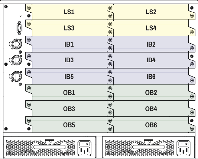
Example
»GETALL /HEALTH/IB5
«pr /HEALTH/IB5.Status=Operational
«pr /HEALTH/IB5.ProductName=MX2M-DH-4DP12-IB
«pr /HEALTH/IB5.SerialNumber=00006522
«pr /HEALTH/IB5.PartNumber=91120049
«pr /HEALTH/IB5.UpTime=343393
«pr /HEALTH/IB5.TemperatureState=Ok
«pr /HEALTH/IB5.VoltageState=Ok
«pr /HEALTH/IB5.OverallHealthState=Ok
«pr /HEALTH/IB5.Temperature0=45.30 C;0.00;115.00;0.00;125.00;34.58;46.52;
«pr /HEALTH/IB5.Voltage0=5.01 V;4.85;5.15;4.75;5.25;4.96;5.01;
«pr /HEALTH/IB5.Voltage1=3.30 V;3.20;3.40;3.14;3.47;3.30;3.33;
«pr /HEALTH/IB5.Voltage2=1.79 V;1.75;1.85;1.71;1.89;1.79;1.79;
«pr /HEALTH/IB5.Voltage3=1.02 V;0.97;1.03;0.95;1.05;1.00;1.02;
«pr /HEALTH/IB5.Voltage4=1.00 V;0.97;1.03;0.95;1.05;0.99;1.00;
8.17.13. Querying the Health State of a PSU Drawer
The query returns with the actual health status information about the selected PSU drawer.
Command and Response
»GETALL·/HEALTH/<PSU>
«pr·/HEALTH/<PSU>.Enabled=<logical_value>
«pr·/HEALTH/<PSU>.FanSpeed0=<fanspeed>
«pr·/HEALTH/<PSU>.Temperature0=<temperature>
«pr·/HEALTH/<PSU>.Current0=<current0>
«pr·/HEALTH/<PSU>.Current1=<current1>
«pr·/HEALTH/<PSU>.DcOk0=<logical_value>
«pr·/HEALTH/<PSU>.DcOk1=<logical_value>
«pr·/HEALTH/<PSU>.PowerGood0=<logical_value>
«pr·/HEALTH/<PSU>.PowerGood1=<logical_value>
«pr·/HEALTH/<PSU>.TemperatureState=<status>
«pr·/HEALTH/<PSU>.CurrentState=<status>
«pr·/HEALTH/<PSU>.FanState=<status>
«pr·/HEALTH/<PSU>.PowerDrawerState=<status>
«pr·/HEALTH/<board>.OverallHealthState=<status>
«pr·/HEALTH/<board>.Status=<status>
«pr·/HEALTH/<PSU>.ProductName=<product_name>
«pr·/HEALTH/<PSU>.SerialNumber=<serial_number>
«pr·/HEALTH/<PSU>.PartNumber=<part_number>
Parameters
|
Identifier |
Parameter description |
Value |
Value description |
|
<PSU> |
The identifier of the PSU drawer. |
POWERDRAWER1 |
PSU drawer 1 |
|
POWERDRAWER2 |
PSU drawer 2 |
Layout of the Matrix

Example
»GETALL /HEALTH/POWERDRAWER1
«pr /HEALTH/POWERDRAWER1.Enabled=true
«pr /HEALTH/POWERDRAWER1.FanSpeed0=0.00 RPM;10.00;65535.00;0.00;65535.00;0.00;0.00
«pr /HEALTH/POWERDRAWER1.Temperature0=0.00 C;0.00;100.00;0.00;110.00;0.00;0.00
«pr /HEALTH/POWERDRAWER1.Current0=59.11 A;0.00;38.00;0.00;42.00;59.11;59.11
«pr /HEALTH/POWERDRAWER1.Current1=0.00 A;0.00;14.00;0.00;15.60;0.00;0.00
«pr /HEALTH/POWERDRAWER1.DcOk0=true
«pr /HEALTH/POWERDRAWER1.DcOk1=true
«pr /HEALTH/POWERDRAWER1.PowerGood0=true
«pr /HEALTH/POWERDRAWER1.PowerGood1=true
«pr /HEALTH/POWERDRAWER1.TemperatureState=OK
«pr /HEALTH/POWERDRAWER1.CurrentState=OK
«pr /HEALTH/POWERDRAWER1.FanState=OK
«pr /HEALTH/POWERDRAWER1.PowerDrawerState=Operational
«pr /HEALTH/POWERDRAWER1.OverallHealthState=OK
«pr /HEALTH/POWERDRAWER1.Status=Operational
«pr /HEALTH/POWERDRAWER1.ProductName=MX2M-PSU-500-F
«pr /HEALTH/POWERDRAWER1.SerialNumber=87654321
«pr /HEALTH/POWERDRAWER1.PartNumber=
8.17.14. Querying the Health State of the HSMB
The query returns with the actual health status information about the High Speed Motherboard (HSMB).
Command and Response
»GETALL·/HEALTH/HSMB
«pr·/HEALTH/HSMB.Voltage0_1V0=<voltage0>
«pr·/HEALTH/HSMB.Voltage1_1V2=<voltage1>
«pr·/HEALTH/HSMB.Voltage2_1V5=<voltage2>
«pr·/HEALTH/HSMB.Voltage3_3V3=<voltage3>
«pr·/HEALTH/HSMB.Voltage4_5V0=<voltage4>
«pr·/HEALTH/HSMB.Voltage5_12V0=<voltage5>
«pr·/HEALTH/HSMB.Voltage6_48V0=<voltage6>
«pr·/HEALTH/HSMB.Temperature0=<temperature0>
«pr·/HEALTH/HSMB.Temperature1=<temperature1>
«pr·/HEALTH/HSMB.Temperature2=<temperature2>
«pr·/HEALTH/HSMB.FanSpeed0=<fanspeed0>
«pr·/HEALTH/HSMB.FanSpeed1=<fanspeed1>
«pr·/HEALTH/HSMB.FanSpeed2=<fanspeed2>
«pr·/HEALTH/HSMB.UnevenCurrentShare=<logical_value>
«pr·/HEALTH/HSMB.BoardsInRightSlotState=<status>
«pr·/HEALTH/HSMB.TemperatureState=<status>
«pr·/HEALTH/HSMB.VoltageState=<status>
«pr·/HEALTH/HSMB.FanState=<status>
«pr·/HEALTH/HSMB.OverallHealthState=<status>
Example
»GETALL /HEALTH/HSMB
«pr /HEALTH/HSMB.Voltage0_1V0=1.04 V;1.02;1.08;1.00;1.10;1.03;1.04
«pr /HEALTH/HSMB.Voltage1_1V2=1.17 V;1.16;1.24;1.14;1.26;1.17;1.17
«pr /HEALTH/HSMB.Voltage2_1V5=1.48 V;1.46;1.55;1.43;1.58;1.48;1.48
«pr /HEALTH/HSMB.Voltage3_3V3=3.32 V;3.20;3.40;3.14;3.47;3.32;3.32
«pr /HEALTH/HSMB.Voltage4_5V0=5.06 V;4.95;5.25;4.85;5.36;5.06;5.12
«pr /HEALTH/HSMB.Voltage5_12V0=0.26 V;11.50;12.60;11.00;13.00;0.26;0.26
«pr /HEALTH/HSMB.Voltage6_48V0=0.00 V;46.00;52.00;44.00;56.00;0.00;0.00
«pr /HEALTH/HSMB.Temperature0=65.00 C;0.00;75.00;0.00;85.00;0.00;72.50
«pr /HEALTH/HSMB.Temperature1=72.50 C;0.00;75.00;0.00;85.00;65.00;72.50
«pr /HEALTH/HSMB.Temperature2=72.50 C;0.00;75.00;0.00;85.00;65.00;72.50
«pr /HEALTH/HSMB.FanSpeed0=0.00 RPM;10.00;65535.00;0.00;65535.00;0.00;0.00
«pr /HEALTH/HSMB.FanSpeed1=0.00 RPM;10.00;65535.00;0.00;65535.00;0.00;0.00
«pr /HEALTH/HSMB.FanSpeed2=0.00 RPM;10.00;65535.00;0.00;65535.00;0.00;0.00
«pr /HEALTH/HSMB.UnevenCurrentShare=false
«pr /HEALTH/HSMB.BoardsInRightSlotState=OK
«pr /HEALTH/HSMB.TemperatureState=OK
«pr /HEALTH/HSMB.VoltageState=OK
«pr /HEALTH/HSMB.FanState=OK
«pr /HEALTH/HSMB.OverallHealthState=OK
8.17.15. Querying the Health State of the CECU
The query returns with the actual health status information about the Central Electronic Control Unit (CECU).
Command and Response
»GETALL·/HEALTH/CECU
«pr·/HEALTH/CECU.Temperature0=<temperature>
«pr·/HEALTH/CECU.TemperatureState=<status>
«pr·/HEALTH/CECU.OverallHealthState=<status>
Example
»GETALL /HEALTH/CECU
«pr /HEALTH/CECU.Temperature0=47.72 C;0.00;65.00;0.00;70.00;44.24;53.52
«pr /HEALTH/CECU.TemperatureState=OK
«pr /HEALTH/CECU.OverallHealthState=OK
ATTENTION!Calling the ApplySettings() method after the network setting is always required. See the details in the Applying the Network Settings section. #network #dhcp #ipaddress
8.18.1. Querying the DHCP State
Command and Response
»GET·/MANAGEMENT/NETWORK.DhcpEnabled
«pw·/MANAGEMENT/NETWORK.DhcpEnabled=<logical_value>
Parameters
The <logical_value> can be true or false.
Example
»GET /MANAGEMENT/NETWORK.DhcpEnabled
«pw /MANAGEMENT/NETWORK.DhcpEnabled=true
8.18.2. Changing the DHCP State
Command and Response
»SET·/MANAGEMENT/NETWORK.DhcpEnabled=<logical_value>
«pw·/MANAGEMENT/NETWORK.DhcpEnabled=<logical_value>
Parameters
The <logical_value> can be set to true or false.
Example
»SET /MANAGEMENT/NETWORK.DhcpEnabled=false
«pw /MANAGEMENT/NETWORK.DhcpEnabled=false
8.18.3. Querying the IP Address
Command and Response
»GET·/MANAGEMENT/NETWORK.IpAddress
«pr·/MANAGEMENT/NETWORK.IpAddress=<IP_address>
Example
»GET /MANAGEMENT/NETWORK.IpAddress
«pr /MANAGEMENT/NETWORK.IpAddress=192.168.0.100
8.18.4. Changing the IP Address (Static)
Command and Response
»SET·/MANAGEMENT/NETWORK.StaticIpAddress=<IP_address>
«pw·/MANAGEMENT/NETWORK.StaticIpAddress=<IP_address>
Example
»SET /MANAGEMENT/NETWORK.StaticIpAddress=192.168.0.85
«pw /MANAGEMENT/NETWORK.StaticIpAddress=192.168.0.85
8.18.5. Querying the Subnet Mask
Command and Response
»GET·/MANAGEMENT/NETWORK.NetworkMask
«pr·/MANAGEMENT/NETWORK.NetworkMask=<netmask>
Example
»GET /MANAGEMENT/NETWORK.NetworkMask
«pr /MANAGEMENT/NETWORK.NetworkMask=255.255.255.0
8.18.6. Changing the Subnet Mask (Static)
Command and Response
»SET·/MANAGEMENT/NETWORK.StaticNetworkMask=<netmask>
«pw·/MANAGEMENT/NETWORK.StaticNetworkMask=<netmask>
Example
»SET /MANAGEMENT/NETWORK.StaticNetworkMask=255.255.255.0
«pw /MANAGEMENT/NETWORK.StaticNetworkMask=255.255.255.0
8.18.7. Querying the Gateway Address
Command and Response
»GET·/MANAGEMENT/NETWORK.GatewayAddress
«pr·/MANAGEMENT/NETWORK.GatewayAddress=<gw_address>
Example
»GET /MANAGEMENT/NETWORK.GatewayAddress
«pr /MANAGEMENT/NETWORK.GatewayAddress=192.168.0.1
8.18.8. Changing the Gateway Address (Static)
Command and Response
»SET·/MANAGEMENT/NETWORK.StaticGatewayAddress=<gw_address>
«pw·/MANAGEMENT/NETWORK.StaticGatewayAddress=<gw_address>
Example
»SET /MANAGEMENT/NETWORK.StaticGatewayAddress=192.168.0.1
«pw /MANAGEMENT/NETWORK.StaticGatewayAddress=192.168.0.1
8.18.9. Applying the Network Settings
Command and Response
»CALL·/MANAGEMENT/NETWORK:ApplySettings()
«mO·/MANAGEMENT/NETWORK:ApplySettings
Example
»CALL /MANAGEMENT/NETWORK:ApplySettings()
«mO /MANAGEMENT/NETWORK:ApplySettings
8.19. RS-232 Port Configuration
8.19.1. Enabling/Disabling the Port
Command and Response
»SET·/MANAGEMENT/SERIAL.Enabled=<logical_value>
«pw·/MANAGEMENT/SERIAL.Enabled=<logical_value>
Parameters
|
Parameter |
Parameter description |
Value |
Value description |
|
<logical_value> |
Port enable/disable setting |
true |
The port is enabled. |
|
false |
The port is disabled. |
Example
»SET /MANAGEMENT/SERIAL.Enabled=true
«pw /MANAGEMENT/SERIAL.Enabled=true
Command and Response
»SET·/MANAGEMENT/SERIAL.Baudrate=<baudrate>
«pw·/MANAGEMENT/SERIAL.Baudrate=<baudrate>
Parameters
|
Parameter |
Parameter description |
Value |
Value description |
|
<baudrate> |
Baud rate value |
0 |
0 |
|
200 |
200 |
||
|
300 |
300 |
||
|
600 |
600 |
||
|
1200 |
1200 |
||
|
1800 |
1800 |
||
|
2400 |
2400 |
||
|
4800 |
4800 |
||
|
9600 |
9600 |
||
|
19200 |
19200 |
||
|
38400 |
38400 |
||
|
57600 |
57600 |
||
|
115200 |
115200 |
Example
»SET /MANAGEMENT/SERIAL.Baudrate=57600
«pw /MANAGEMENT/SERIAL.Baudrate=57600
Command and Response
»SET·/MANAGEMENT/SERIAL.DataBits=<databits>
«pw·/MANAGEMENT/SERIAL.DataBits=<databits>
Parameters
|
Parameter |
Parameter description |
Value |
Value description |
|
<databits> |
Databits value |
8 |
8 databits |
|
9 |
9 databits |
Example
»SET /MANAGEMENT/SERIAL.DataBits=8
«pw /MANAGEMENT/SERIAL.DataBits=8
Command and Response
»SET·/MANAGEMENT/SERIAL.Parity=<parity>
«pw·/MANAGEMENT/SERIAL.Parity=<parity>
Parameters
|
Parameter |
Parameter description |
Value |
Value description |
|
<parity> |
Parity value |
None |
None |
|
Odd |
Odd |
||
|
Even |
Even |
||
|
Mark |
Mark |
||
|
Space |
Space |
Example
»SET /MANAGEMENT/SERIAL.Parity=Even
«pw /MANAGEMENT/SERIAL.Parity=Even
8.19.5. Setting the Stopbits
Command and Response
»SET·/MANAGEMENT/SERIAL.StopBits=<stopbits>
«pw·/MANAGEMENT/SERIAL.StopBits=<stopbits>
Parameters
|
Parameter |
Parameter description |
Value |
Value description |
|
<stopbits> |
Stop bits value |
1 |
1 |
|
2 |
2 |
Example
»SET /MANAGEMENT/SERIAL.StopBits=1
«pw /MANAGEMENT/SERIAL.StopBits=1
8.19.6. Setting the Protocol
Command and Response
»SET·/MANAGEMENT/SERIAL.Protocol=<protocol>
«pw·/MANAGEMENT/SERIAL.Protocol=<protocol>
Parameters
|
Parameter |
Parameter description |
Value |
Value description |
|
<protocol> |
Command protocol on the serial port |
LW2 |
Lightware LW2 command protocol |
|
LW3 |
Lightware LW3 command protocol |
||
|
P#2 |
Third-party command protocol |
Example
»SET /MANAGEMENT/SERIAL.Protocol=LW3
«pw /MANAGEMENT/SERIAL.Protocol=LW3
8.19.7. Recalling Factory Default Settings on the Serial Port
Command and Response
»CALL·/MANAGEMENT/SERIAL:factoryDefault()
«mO·/MANAGEMENT/SERIAL:factoryDefault=
Example
»CALL /MANAGEMENT/SERIAL:factoryDefault()
«mO /MANAGEMENT/SERIAL:factoryDefault=
INFO:See the factory default values for the RS-232 port in the Factory Default Settings section.
INFO:The hidden first 2 bytes of the CEC command are static, they refer to the logical address of the sender and the addressee. When the port is input, it is always 04 (from TV to Playback device 1); when the port is output, it is always 40 (from Playback device 1 to TV). Broadcast addressing is also possible (in this case it is 0F or 4F). #cec
INFO:The port numbering of the relevant I/O boards can be found in the Video Input/Output Port Numbering section.
The following settings are valid only for the following input and output boards:
▪MX2M-4HDMI20-IB
▪MX2M-4TPX-IB
▪MX2M-4OPTJ-IB
▪MX2M-4HDMI20-OB
▪MX2M-4OPTJ-OB
8.20.1. Sending a CEC Command in Text Format
Command and Response
»CALL·/MEDIA/PORTS/VIDEO/<in|out>/PARAMETERS/CEC:send(<command>)
«mO·/MEDIA/PORTS/VIDEO/<in|out>/PARAMETERS/CEC:send
Parameters
The followings are accepted as <command>:
|
image_view_on |
standby |
text_view_on |
active_source |
give_power_status |
|
get_cec_version |
set_osd |
clear_osd |
Example
»CALL /MEDIA/PORTS/VIDEO/O1/PARAMETERS/CEC:send(power_on)
«mO /MEDIA/PORTS/VIDEO/O1/PARAMETERS/CEC:send
8.20.2. Press&Release Commands
CEC commands below are called 'push-button commands', like a button in a remote controller, e.g. volume up/down. When the CEC command is sent, the 'release' command is also sent in the background. Certain devices require this feature for the proper working, but this is necessary only for push-button commands.
Command and Response
»CALL·/MEDIA/PORTS/VIDEO/<in|out>/PARAMETERS/CEC:sendClick(<command>)
«mO·/MEDIA/PORTS/VIDEO/<in|out>/PARAMETERS/CEC:sendClick
Parameters
The following are accepted as a <command>:
|
ok |
number_2 |
input_select |
rewind |
select_media_4 |
|
back |
number_3 |
display_info |
fast_forward |
select_media_5 |
|
up |
number_4 |
power_legacy |
eject |
power_toggle |
|
down |
number_5 |
page_up |
skip_forward |
power_on |
|
left |
number_6 |
page_down |
skip_backward |
power_off |
|
right |
number_7 |
volume_up |
3d_mode |
stop_function |
|
root_menu |
number_8 |
volume_down |
stop_record |
f1 |
|
setup_menu |
number_9 |
mute_toggle |
pause_record |
f2 |
|
contents_menu |
dot |
mute |
play_forward |
f3 |
|
favorite_menu |
enter |
unmute |
play_reverse |
f4 |
|
media_top_menu |
clear |
play |
select_next_media |
|
|
media_context_menu |
channel_up |
stop |
select_media_1 |
|
|
number_0 |
channel_down |
pause |
select_media_2 |
|
|
number_1 |
sound_select |
record |
select_media_3 |
Example
»CALL /MEDIA/PORTS/VIDEO/O1/PARAMETERS/CEC:sendClick(play)
«mO /MEDIA/PORTS/VIDEO/O1/PARAMETERS/CEC:sendClick
Sending the OSD string consists of two steps. First, set the CEC.OsdString property with the desired text, after that call the CEC.send(set_osd) method.
Step 1 – Setting the CEC.OsdString Property
Command and Response
»SET·/MEDIA/PORTS/VIDEO/<in|out>/PARAMETERS/CEC.OsdString=<text>
«pw·/MEDIA/PORTS/VIDEO/<in|out>/PARAMETERS/CEC.OsdString=<text>
Parameters
<text> Letters (A-Z) and (a-z), hyphen (-), underscore (_), numbers (0-9), and dot (.). Max length: 14 characters.
Example
»SET /MEDIA/PORTS/VIDEO/I1/PARAMETERS/CEC.OsdString=Lightware
«pw /MEDIA/PORTS/VIDEO/I1/PARAMETERS/CEC.OsdString=Lightware
Step 2 – Call the CEC.send(set_osd) method
Command and Response
»CALL·/MEDIA/PORTS/VIDEO/<in|out>/PARAMETERS/CEC:send(set_osd)
«mO /MEDIA/PORTS/VIDEO/<in|out>/PARAMETERS/CEC:send
Example
»CALL /MEDIA/PORTS/VIDEO/I1/PARAMETERS/CEC:send(set_osd)
«mO /MEDIA/PORTS/VIDEO/I1/PARAMETERS/CEC:send
8.20.4. Sending a CEC Command in Hexadecimal Format
Command and Response
»CALL·/MEDIA/PORTS/VIDEO/<in|out>/PARAMETERS/CEC:sendHex(<hex_code>)
«mO·/MEDIA/PORTS/VIDEO/<in|out>/PARAMETERS/CEC:sendHex
Parameters
<hex_code> Accepted command is max. 30 characters long (15 byte) in hexadecimal format.
Example
»CALL /MEDIA/PORTS/VIDEO/I1/PARAMETERS/CEC:sendHex(8700E091)
«mO /MEDIA/PORTS/VIDEO/I1/PARAMETERS/CEC:sendHex
8.21. Firmware Updating of the I/O Boards
The firmware package files of all available MX2M series I/O boards are built-in into the firmware package of the MX2M matrix frame. The updating procedure can be applied inside the frame without using any external application like Lightware Device Updater V2 (LDU2).
Parameters
|
Identifier |
Parameter description |
Value |
Value description |
|
<board> |
The identifier of the board. |
IB1...IB6 |
Input board ID, the values can be IB1, IB2, IB3, IB4, IB5 or IB6. |
|
OB1...OB6 |
Output board ID, the values can be OB1, OB2, OB3, OB4, OB5 or OB6. |
||
|
LS1...LS4 |
Auxiliary (LS - Low Speed) board ID, the values can be LS1, LS2, LS3 or LS4. |
8.21.1. Querying the Firmware Version of the I/O Board
Command and Response #firmwareversion
»GET·/SYS/<board>.PackageVersion
«pr·/SYS/<board>.PackageVersion=<firmware_version>
Example
»GET /SYS/LS1.PackageVersion
«pr /SYS/LS1.PackageVersion=1.0.0b20
8.21.2. Launching the Firmware Update Procedure
Calling the method launches the firmware update procedure on the selected I/O board.
Command and Response
»CALL·/SYS/<board>:updateFirmware()
«mO·/SYS/<board>:updateFirmware=
Example
»CALL /SYS/IB1:updateFirmware()
«mO /SYS/IB1:updateFirmware=
8.21.3. Cancelling the Firmware Update Procedure
Calling the method cancels the running firmware update procedure on the selected I/O board.
Command and Response
»CALL·/SYS/<board>:cancelFirmwareUpdate()
«mO·/SYS/<board>:cancelFirmwareUpdate=
Example
»CALL /SYS/OB1:cancelFirmwareUpdate()
«mO /SYS/OB1:cancelFirmwareUpdate=
8.21.4. Querying the Update Progress Status
The query returns with the logical value that tells whether there is a board in the matrix undergoing a firmware update or not.
Command and Response
»GET·/SYS/UPDATE.BoardUpdateInProgress
«pr·/SYS/UPDATE.BoardUpdateInProgress=<logical_value>
Parameters
|
Identifier |
Parameter description |
Value |
Value description |
|
<logical_value> |
Update in progress |
true |
One or more I/O boards are undergoing a firmware update. |
|
false |
No I/O board is undergoing a firmware update. |
Example
»GET /SYS/UPDATE.UpdateInProgress
«pr /SYS/UPDATE.UpdateInProgress=true
8.21.5. Querying the List of Updating Boards
The query returns with the list of the I/O boards that are currently undergoing a firmware update.
Command and Response
»GET·/SYS/UPDATE.BoardsInUpdateState
«pr·/SYS/UPDATE.BoardsInUpdateState=<board_slot1>;<board_slot2>;...<board_slotN>
Example
»GET /SYS/UPDATE.BoardsInUpdateState
«pr /SYS/UPDATE.BoardsInUpdateState=LS2;IB3;OB5
8.21.6. Querying the Overall Board Update Status
The query returns with the the overall progress of the board update.
Command and Response
»GET·/SYS/UPDATE.BoardUpdateStatus
«pr·/SYS/UPDATE.BoardUpdateStatus=<status>
Example
»GET /SYS/UPDATE.BoardUpdateStatus
«pr /SYS/UPDATE.BoardUpdateStatus=3/3
Explanation
Firmware upgarde procedure of three I/O boards out of three is successfully completed.
8.22. LW3 Protocol Commands - Quick Summary
The MX2M series matrix switchers can be updated using Lightware Device Updater V2 (LDU2) software via Ethernet. The firmware pack with the necessary components (*.lfp2 file) for your specific product and the LDU2 application can be downloaded from the Support page of our website: www.lightware.com.
ATTENTION!While the firmware is being updated, the normal operation mode is suspended, as the matrix is switched to bootload mode. Signal processing is not performed. Do not interrupt the firmware update. If any problem occurs, reboot the device and restart the process.
ATTENTION!The firmware update process has an effect on the configuration and the settings of the device. For more details, please see the Keeping the Configuration Settings section before the update.
9.1. Preparation
Most Lightware devices can be controlled over several interfaces (e.g. Ethernet, USB, RS-232). But the firmware can usually be updated over one dedicated interface, which is the Ethernet in most cases.
If you want to update the firmware of one or more devices, you need the following:
▪LFP2 file,
▪LDU2 software installed on your PC or Mac.
Both can be downloaded from www.lightware.com/downloads.
Optionally, you can download the release notes file in HTML format.
9.1.1. About the Firmware Package (LFP2 File)
All the necessary tools and binary files are packed into the LFP2 package file. You need only this file to do the update on your device.
▪This allows the use of the same LFP2 package for different devices.
▪The package contains all the necessary components, binary, and other files.
▪The release notes is included in the LFP2 file, which is displayed in the window where you select the firmware package file in LDU2.
9.1.2. LDU2 Installation
ATTENTION!Minimum system requirement: 2 GB RAM. The minimum screen resolution is 1600x900.
ATTENTION!Certain ports are used for the communication in the background; please check the list in the Applied Ports (Network Settings) section.
INFO:The Windows, Mac and Linux applications have the same look and functionality.
Download the software from www.lightware.com/downloads.
Installation in case of Windows OS
Run the installer. If the User Account Control displays a pop-up message, click Yes.
Installation Modes
|
Normal install |
Snapshot install |
|
Available for Windows, macOS and Linux |
Available for Windows |
|
The installer can update only this instance |
Cannot be updated |
|
Only one updateable instance can exist for all users |
More than one different version can be installed for each user |
ATTENTION!Using the default Normal install is highly recommended.
INFO:If you have a previously installed version, you will be prompted to remove the old version before installing the new one.
Installation in case of macOS

Mount the DMG file by double clicking on it, and drag the LDU2 icon over the Applications icon to copy the program into the Applications folder. If you want to copy LDU2 into another location, just drag the icon over the desired folder.
ATTENTION!Please check the firewall settings on the macOS device. LDC needs to be added to the exceptions of the blocked software for the proper operation.
INFO:This type of installer is equal to the Normal install of Windows.
Installation in case of Linux

Step 1.Download the archive file (tar.gz) from www.lightware.com/downloads and unpack it to a temp folder.
Step 2.Run the install_ldu2.sh file in the temp folder. The script will install LDU2 into the following folder: HOME/.local/share/lightware/ldu2.
Step 3.The folder above will contain this file: LightwareDeviceUpdaterV2.sh, which can be used to start LDU2.
9.2. Running the Software
ATTENTION!The computer that runs LDU2 and the target device (that will be updated) must be in the same subnet. The update cannot be performed behind a firewall or gateway.
You have two options:
▪Starting the LDU2 by double-clicking on the shortcut/program file, or
▪Double-clicking on an LFP2 file.
9.2.1. LDU2 Interfaces
The software can be used over:
▪The Graphical User Interface (GUI), or by
▪The Command Line Interface (CLI).
LDU2 Auto-Update
At startup, the software checks whether a newer version is available on the web.

Main Screen

When the software is started by the shortcut, the device discovery screen appears. Press the Discover Devices button to start finding the Lightware devices:
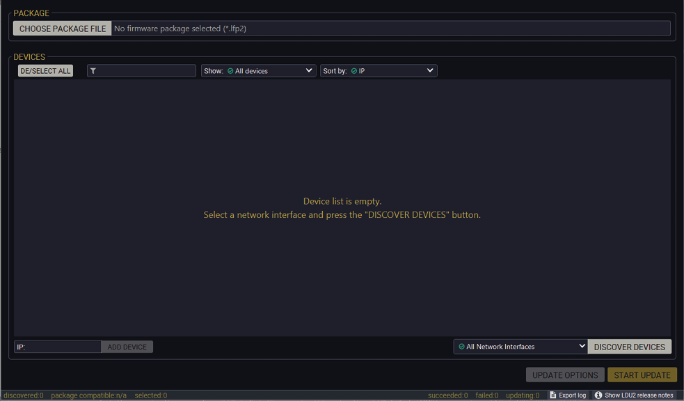
LDU2 welcome screen
If you start the software by double-clicking on the LFP2 file, the firmware will be loaded. Press the Discover devices button; all the devices will be listed that are compatible with the selected firmware pack.
INFO:If you press the Choose package file button, the release notes of the LFP2 file will be displayed in the right panel; see the Step 1. Select the Firmware Package section.
Device List
When the discovery has completed, the devices available on the network are listed in the application.
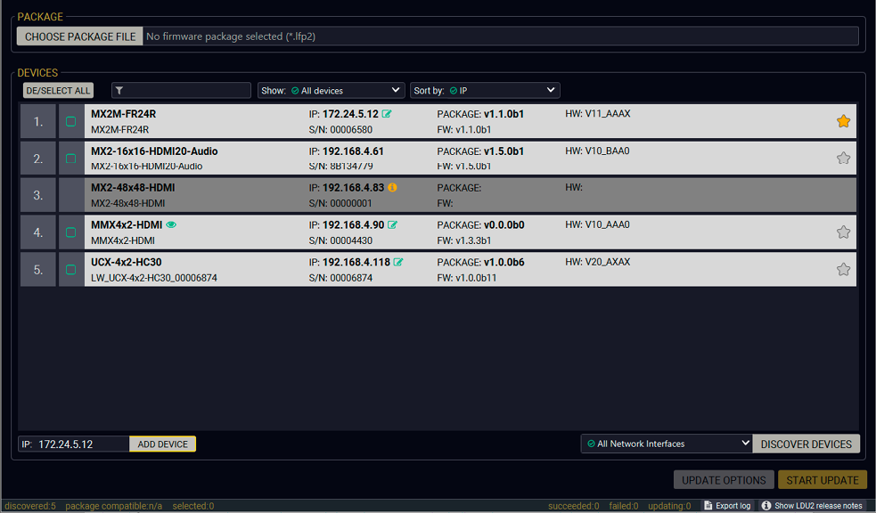
If the desired device is not discovered, you can add it by typing the IP address in the dedicated field and pressing the Add device button.
Devices may also be added manually by typing the IP address in the box near the bottomof the screen. From LDU2 version v2.16.1, manual addition of devices can also be done using the hostname.
ATTENTION!If the device cannot be added by the hostname, please use the IP address.
Legend of the Icons
|
|
IP address editor |
The IP address of the device can be changed in the pop-up window. |
|
|
Identify me |
Clicking on the icon results in the front panel LEDs blinking for 10 seconds, which helps to identify the device phisically. |
|
|
Favorite device |
The device has been marked, thus the IP address is stored. When a device is connected with that IP address, the star will be highlighted in that line. |
|
|
Further information available |
Device is unreachable. Change the IP address by pressing the IP address editor icon or use the front panel buttons (if available). |

|
Service mode |
The device is in bootload mode. Backup and restore cannot be performed in this case. |


ATTENTION!While the firmware is being updated, the normal operation mode is suspended, as the device is switched to bootload mode. Signal processing is not performed. Do not interrupt the firmware update. If any problem occurs, reboot the unit and restart the process.
Keeping the Configuration Settings
By default, device configuration settings are restored when firmware update is finished. If factory reset has been chosen in the parameters window, all device settings will be erased. In the case of factory reset, you can save the settings of the device in the Lightware Device Controller software and restore it later.
The following flow chart demonstrates how this function works in the background.
Step 1.Create a backup
The current configuration of the device is being saved into a configuration backup file on your computer.
Step 2.Start the Update
The device reboots and starts in bootload mode (firmware update mode).
Step 3.Upgrade
The CPU firmware is changed to the new one.
Step 4.Factory reset
All configuration settings are restored to the factory default values.
Step 5.Conversion / Restore
The firmware package checks the backup data before the restoration procedure, and if it is necessary, a conversion is applied to avoid incompatibility problems between the firmware versions. All configuration settings are restored to the device after the conversion.
If the factory default option is selected in the Parameters window, the conversion / restore procedure will not be performed!
Step 6.Finish
Once the firmware update procedure is finished, the device reboots and is ready to use.
9.4. Updating Via GUI
Step 1. Select the Firmware Package
Click on the Choose Firmware Package button and navigate to the location where the LFP2 file of the matrix frame is saved. When you click on the name of package, the preview of the release notes is displayed on the right side.
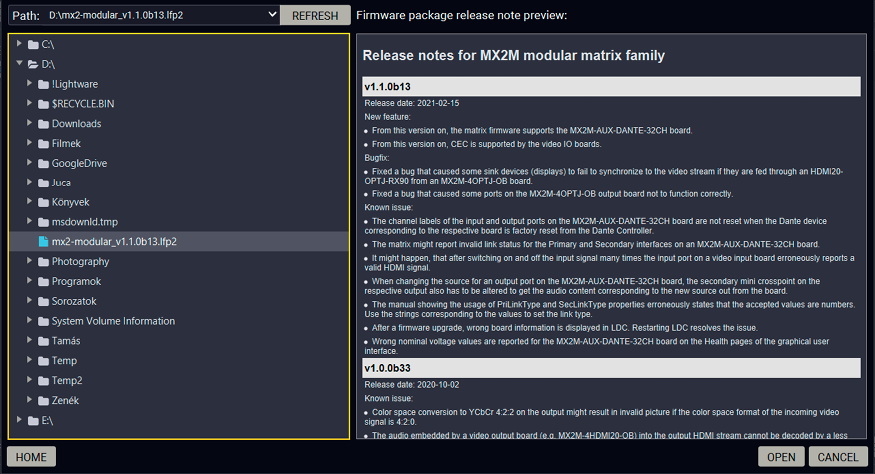
Firmware file browser and the release notes window
After the package file is loaded, the list is filtered to show compatible devices only. The current firmware version of the device is highlighted in orange if it is different from the version of the package loaded.
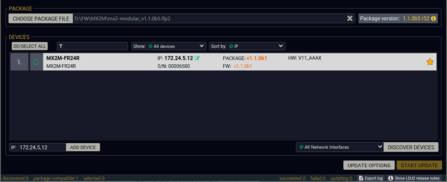
Filtered device list based on the selected firmware package
Step 2. Select the Desired Device for Updating
Pick the device for updating. The selected line will be highlighted in green.

The remote unit is selected for updating
Step 3. Check the Update Parameters.

ATTENTION!The default settings in the Update options window should be fine for most cases. Please do not modify them if it is not necessary.
Click on the Update options button to configure the firmware update.
Configuration Backup and Restore
▪Restore device configuration settings: the configuration settings of the endpoint devices will be restored after the firmware update.
▪Factory reset the device: if it is checked, all user settings and parameters will be cleared and the factory default settings will be applied to the device when the update is done. See the whole list of factory default settings of the endpoint device in the Factory Default Settings section.
▪Backup folder: Set the path of the device configuration backup file, which is created automatically. The default path is USER_HOME/.ldu2/backup.
Advanced Settings
▪Do not make any backup file: if it is checked, the configuration of the matrix switcher will not be restored after the firmware update.
Once the parameters are set, click on the Apply button to save the settings.
Step 4. Start the Update and Wait until It is Finished.
Click on the Start Update button to start the procedure.
The status is shown in percent in the right side of the device line and the status of all of the procedures is shown in the lower light green progress bar.

Firmware update is in progress
INFO:The device might reboot several times during the firmware update procedure.
Step 5. Wait until the Unit Reboots with the New Firmware.
Once the firmware update procedure is completed, the unit reboots with the new firmware.
9.5. Command Line Interface (CLI)
DIFFERENCE:The Command Line Interface is available from LDU2 v2.9.0b9.
The CLI of the LDU2 software is a simple tool for creating scriptable device updates without the need for human interactions. It allows batch updating with the same features that are available in case of GUI usage.
9.5.1. How to Run
Running under Windows® OS
The installer of LDU2 puts the following file into the installation folder:
LightwareDeviceUpdaterV2_CLI.cmd
CLI is available via this file, the exe is not suitable for that purpose. Open a command line window to execute or test the features directly.
Step 1.Open an Explorer window where the cmd file is located, the default is:
c:\Program Files (x86)\Lightware\Lightware Device Updater V2\LightwareDeviceUpdaterV2_CLI.cmd.
Step 2.Click on the address line (highlighed with blue in the picture), type cmd.exe and press enter. The command interpreter window of Windows is opened at the path of the LDU2 install folder.

Step 3.Now you can use the LightwareDeviceUpdaterV2_CLI.cmd file with the commands and options, which are described in the coming sections:
Running under Linux
The Command Line Interface under Linux Operating Systems can be run by the following:
LightwareDeviceUpdaterV2.sh.
Running an update:
bash LightwareDeviceUpdaterV2.sh update --ip 172.24.5.27 --package ~/Downloads/mx2-modular_v1.2.0b6.lfp2
The commands and options are the same under Windows® and Linux, too. The following sections contain examples with LightwareDeviceUpdaterV2_CLI.cmd.
9.5.2. How to Use
Command Structure
The commands can be run over CLI in the following way:
LightwareDeviceUpdaterV2_CLI.cmd [command] [options]
[Command]: a certain command described in the coming sections; only one command can be run at a time.
[Options]: mandatory and/or optional parameters of the command, if any. Optional parameters have a default value, which can be found at each affected command. You only have to define the parameter if you want to apply a different value. The order of the options is arbitrary.
Important Notes
▪CLI is case-sensitive (including commands, options and other parameters).
▪There is no limit regarding the number of the devices to update. At most, 20 devices are updated simoultaneously, when one of them is finished, the next (21st) will be started automatically.
▪If an update is failed, the IP address of the affected device(s) are listed at the end.
9.6. CLI Commands
INFO:The commands and options described in the following sections are the same under Windows® and Linux, too. The examples contain LightwareDeviceUpdaterV2_CLI.cmd.
About the Examples
▪Sent command is in blue, response is in grey.
▪If the response in practice is longer than listed in the example, this symbol can be seen: [...].
9.6.1. Help
The defined commands and options can be listed by the help command.
Command
LightwareDeviceUpdaterV2_CLI.cmd help
Example
C:\Program Files (x86)\Lightware\Lightware Device Updater V2>LightwareDeviceUpdaterV2_CLI.cmd help
C:\Program Files (x86)\Lightware\Lightware Device Updater V2>lib\jre\bin\java.exe -jar lib\ldu2.jar help
Command line usage:
Win: LightwareDeviceUpdaterV2_CLI.cmd [command] [options]
Linux: LightwareDeviceUpdaterV2.sh [command] [options]
Commands:
* help
* version
* update
* deviceInfo
* restore
* packageOptions
[...]
9.6.2. LDU2 Version
The response shows the version of the LDU2 and the version of the Script API (the Application Programming Interface that is used by the LDU2 and the script).
Command
LightwareDeviceUpdaterV2_CLI.cmd version
Example
C:\Program Files (x86)\Lightware\Lightware Device Updater V2>LightwareDeviceUpdaterV2_CLI.cmd version
C:\Program Files (x86)\Lightware\Lightware Device Updater V2>lib\jre\bin\java.exe -jar lib\ldu2.jar version
LDU2 version: 2.9.0b9
Script API version: 1.3.9
9.6.3. Checking For New LDU2 Version
The following command can be used to check if an update of LDU2 is available. This is just a request, since the CLI is not suitable for handling the complete installer of the software.
Command
LightwareDeviceUpdaterV2_CLI.cmd checkForUpdates
Example 1
c:\Program Files (x86)\Lightware\Lightware Device Updater V2>LightwareDeviceUpdaterV2_CLI.cmd checkForUpdates
c:\Program Files (x86)\Lightware\Lightware Device Updater V2>lib\jre\bin\java.exe -jar lib\ldu2.jar checkForUpdates
Current LDU2 version: 2.9.1b1
LDU2 is up-to-date
Example 2
c:\Program Files (x86)\Lightware\Lightware Device Updater V2>LightwareDeviceUpdaterV2_CLI.cmd checkForUpdates
c:\Program Files (x86)\Lightware\Lightware Device Updater V2>lib\jre\bin\java.exe -jar lib\ldu2.jar checkForUpdates
Current LDU2 version: 2.9.1b1
New version is available online: v2.9.2b2
Download URL: http://update.lightware.hu/ldu2/lwr/v2.9.2b2/install_LDU2_v2.9.2b2.exe
9.6.4. Device Info
The most important information about the selected device is displayed; see the example for more details.
Command
LightwareDeviceUpdaterV2_CLI.cmd deviceInfo [options]
Options
|
Option |
Description |
Required? |
|
-i or --ip |
List of IP addresses of devices to be updated |
one of them is mandatory |
|
-n or --hostName |
List of host names of devices to be updated |
|
|
-v or --packageVersion |
Shows installed package version only |
optional |
Example 1
C:\Program Files (x86)\Lightware\Lightware Device Updater V2>LightwareDeviceUpdaterV2_CLI.cmd deviceInfo --ip 192.168.1.12
C:\Program Files (x86)\Lightware\Lightware Device Updater V2>lib\jre\bin\java.exe -jar lib\ldu2.jar deviceInfo --ip 192.168.1.12
Product name: MX2M-FR24R
IP address: 192.168.1.12
Serial number: 00002263
MAC address: a8:d2:36:ff:22:63
Part number: 91540065
Device label: 123
Package version: v1.1.0b6
CPU FW version: v1.1.0b3
HW version: V12_KAA0
Operation mode: Application mode
Example 2
C:\Program Files (x86)\Lightware\Lightware Device Updater V2>LightwareDeviceUpdaterV2_CLI.cmd deviceInfo --ip 192.168.1.12 --packageVersion
C:\Program Files (x86)\Lightware\Lightware Device Updater V2>lib\jre\bin\java.exe -jar lib\ldu2.jar deviceInfo --ip 192.168.1.12 --packageVersion
v1.1.0b6
9.6.5. Update
This command can be used to update the firmware of the devices.
Command
LightwareDeviceUpdaterV2_CLI.cmd update [options]
Options
|
Option |
Description |
Required? |
|
-p or --package |
The path of the firmware package file |
yes |
|
-i or --ip |
List of IP addresses of devices to be updated |
one of them is mandatory |
|
-n or --hostName |
List of host names of devices to be updated |
|
|
-b or --backupFolder |
Folder to create device configuration backup at. Default: USER_HOME/.ldu2/backup |
optional |
|
-f or --factoryDefault |
Apply factory reset during device update. Default: false |
optional |
|
-r or --reportProgress |
Report update progress in percent. Default: false |
optional |
|
Package-specific options |
Certain LFP2 packages have features that can be applied at this command; see the Package Options section. |
optional |
ATTENTION!The configuration is restored automatically if the factory default option is not applied in the update command. In that case, there is no need to run the restore command after the update.
Example
C:\Program Files (x86)\Lightware\Lightware Device Updater V2>LightwareDeviceUpdaterV2_CLI.cmd update --ip 192.168.1.12 --package C:\Firmwares\mx2-modular_v1.2.0b6.lfp2 --reportProgress
C:\Program Files (x86)\Lightware\Lightware Device Updater V2>lib\jre\bin\java.exe -jar lib\ldu2.jar update --ip 192.168.1.12 --package C:\Firmwares\mx2-modular_v1.2.0b6.lfp2 --reportProgress
[2021-05-12 08:59:36.336] [ INFO] [ main] - Device IPs: [192.168.1.12]
[2021-05-12 08:59:39.409] [ INFO] [ main] - All the selected devices are accessible over the network.
[2021-05-12 08:59:39.628] [ INFO] [ main] - All the selected devices are compatible with the specified package.
[2021-05-12 08:59:40.025] [ INFO] [ 192.168.1.12] - Package version: 1.3.2b3
[2021-05-12 08:59:40.092] [ INFO] [ 192.168.1.12] - Login functionality is currently not enabled.
[2021-05-12 08:59:40.129] [ INFO] [ 192.168.1.12] - Creating backup of device settings...
[2021-05-12 08:59:43.582] [ INFO] [ 192.168.1.12] - Backup HTTP enable properties
[2021-05-12 08:59:44.638] [ INFO] [ProgressReporter] - Progress: 2%
[2021-05-12 08:59:46.111] [ INFO] [ 192.168.1.12] - HTTP and HTTP post have got enabled on port 80
[2021-05-12 08:59:46.319] [ INFO] [ 192.168.1.12] - No miniweb file is found on the device.
[2021-05-12 08:59:48.890] [ INFO] [ 192.168.1.12] - HTTP and HTTP post properties have got restored on port 80
[2021-05-12 08:59:48.897] [ INFO] [ 192.168.1.12] - Switching device into bootload mode...
[2021-05-12 08:59:49.640] [ INFO] [ProgressReporter] - Progress: 5%
[...]
The lines containing "ProgressReporter" can be enabled optionally. If it is enabled, the current state is displayed every 5 seconds.
Restores device configuration from a backup file.
TIPS AND TRICKS:This command can be used for uploading a configuration to numerous devices (aka Configuration cloning by CLI).
Command
LightwareDeviceUpdaterV2_CLI.cmd restore [options]
Options
|
Option |
Description |
Required? |
|
-i or --ip |
List of IP addresses of devices to be updated |
one of them is mandatory |
|
-n or --hostName |
List of host names of devices to be updated |
|
|
-b or --backupFile |
The path of the configuration backup file |
yes |
|
-k or --keepOriginalIp |
Do not override the network settings of the device with the ones in the backup file. It comes in handy when multiple devices' configuration is being restored from a single backup file. Default: false |
optional |
ATTENTION!The configuration is restored automatically if the factory default option is not applied in the update command. In that case, there is no need to run the restore command after the update.
Example
C:\Program Files (x86)\Lightware\Lightware Device Updater V2>LightwareDeviceUpdaterV2_CLI.cmd restore --ip 192.168.1.12 --backupFile C:\mybackup.lw3 --keepOriginalIp
C:\Program Files (x86)\Lightware\Lightware Device Updater V2>lib\jre\bin\java.exe -jar lib\ldu2.jar restore --ip 192.168.1.12 --backupFile C:\mybackup.lw3 --keepOriginalIp
[2021-05-12 10:49:36.412] [ INFO] [ main] - Executing configuration restore...
[2021-05-12 10:49:36.425] [ INFO] [ main] - Device IPs: [192.168.1.12]
INFO:The firmware package checks the backup data before the restoration procedure, and if it is necessary, a conversion is applied to avoid incompatibility problems between the firmware versions. In that case, two backup files are created: the original, and a new one with "_converted" suffix. Using the last one for restoring is recommended.
Shows package-specific update options.
Command
LightwareDeviceUpdaterV2_CLI.cmd packageOptions [options]
Options
|
Option |
Description |
Required? |
|
-p or --package |
The path of the firmware package file |
yes |
Example
C:\Program Files (x86)\Lightware\Lightware Device Updater V2>LightwareDeviceUpdaterV2_CLI.cmd packageOptions --package c:\Firmwares\mx2-modular_v1.2.0b6.lfp2
C:\Program Files (x86)\Lightware\Lightware Device Updater V2>lib\jre\bin\java.exe -jar lib\ldu2.jar packageOptions --package c:\Firmwares\mx2-modular_v1.2.0b6.lfp2
Backup and restore options:
--skipPresetsAtRestore : if true, device presets will not be restored. (Default: false)
--uploadDefaultMiniWeb : if true and no custom miniweb is present on the device, the default built-in miniweb will be uploaded to the device. (Default: false)
Test options:
--test : if true, no update will be performed, communication with the device will be tested. (Default: false)
Package option example can be seen in the following section.
9.6.8. Complex Example
The following options are applied:
▪Firmware is updated
▪Factory default settings are restored
C:\Program Files (x86)\Lightware\Lightware Device Updater V2>LightwareDeviceUpdaterV2_CLI.cmd update --ip 192.168.1.12 --factoryDefault --package c:\Firmwares\mx2-modular_v1.2.0b6.lfp2
C:\Program Files (x86)\Lightware\Lightware Device Updater V2>lib\jre\bin\java.exe -jar lib\ldu2.jar update --ip 192.168.1.12 --factoryDefault --package c:\Firmwares\mx2-standalone_v1.7.0b17.lfp2
[2021-05-12 11:22:09.089] [ INFO] [ main] - Device IPs: [192.168.1.12]
[2021-05-12 11:22:12.947] [ INFO] [ main] - All the selected devices are accessible over the network.
[2021-05-12 11:22:13.225] [ INFO] [ main] - All the selected devices are compatible with the specified package.
[2021-05-12 11:22:13.777] [ INFO] [ 192.168.1.12] - Package version: 1.3.2b3
[2021-05-12 11:22:13.878] [ INFO] [ 192.168.1.12] - Login functionality is currently not enabled.
[2021-05-12 11:22:13.896] [ INFO] [ 192.168.1.12] - Switching device into bootload mode...
[2021-05-12 11:22:34.519] [ INFO] [ 192.168.1.12] - Gathering UID information from device...
[2021-05-12 11:22:35.097] [ INFO] [ 192.168.1.12] - UID info - Device IP: 192.168.1.12 Product name: MX2-16x16-DH-8DPi-A-R Product part number: 91310068 Serial number: 00002263 Hardware version: V12_KAA0 MAC address: A8:D2:36:FF:22:63
[2021-05-12 11:22:35.589] [ INFO] [ 192.168.1.12] - Package version on device: 1.3.2b3 r44
[2021-05-12 11:22:35.626] [ INFO] [ 192.168.1.12] - Updating MX2 Standalone series application fw part 1...
[2021-05-12 11:22:36.123] [ INFO] [ 192.168.1.12] - [mx2.bin.ER_IROM1]'s current version on device: 1.3.1b1 r35
[2021-05-12 11:22:36.124] [ INFO] [ 192.168.1.12] - [mx2.bin.ER_IROM1]'s version in the package: 1.3.1b1 r35
[2021-05-12 11:22:52.439] [ INFO] [ 192.168.1.12] - [tps_tx200.bin.ER_IROM1]'s firmware version updated in FVS EEPROM.
[2021-05-12 11:22:52.442] [ INFO] [ 192.168.1.12] - Updating VS100TX fw...
[2021-05-12 11:22:52.920] [ INFO] [ 192.168.1.12] - [vs100_tx.bin]'s current version on device: 1.1.0b0 r0
[2021-05-12 11:22:52.921] [ INFO] [ 192.168.1.12] - [vs100_tx.bin]'s version in the package: 1.1.0b0 r63
[2021-05-12 11:23:06.423] [ INFO] [ 192.168.1.12] - [vs100_tx.bin]'s firmware version updated in FVS EEPROM.
[2021-05-12 11:23:06.425] [ INFO] [ 192.168.1.12] - Updating MX2 Standalone series application fw part 2...
[2021-05-12 11:23:06.903] [ INFO] [ 192.168.1.12] - [mx2.bin.ER_IROM2]'s current version on device: 1.3.1b1 r35
[2021-05-12 11:23:06.904] [ INFO] [ 192.168.1.12] - [mx2.bin.ER_IROM2]'s version in the package: 1.2.0b6 r35
[2021-05-12 11:23:27.858] [ INFO] [ 192.168.1.12] - [mx2.bin.ER_IROM2]'s firmware version updated in FVS EEPROM.
[2021-05-12 11:23:27.860] [ INFO] [ 192.168.1.12] - Updating PS171 FW...
[2021-05-12 11:23:28.338] [ INFO] [ 192.168.1.12] - [mx2_family_ps171.bin]'s current version on device: 1.0.6b0 r0
[2021-05-12 11:23:28.340] [ INFO] [ 192.168.1.12] - [mx2_family_ps171.bin]'s version in the package: 1.2.0b6 r522
[2021-05-12 11:23:44.810] [ INFO] [ 192.168.1.12] - [mx2_family_ps171.bin]'s firmware version updated in FVS EEPROM.
[2021-05-12 11:23:51.412] [ INFO] [ 192.168.1.12] - Setting system information...
[2021-05-12 11:23:57.994] [ INFO] [ 192.168.1.12] - Starting application...
[2021-05-12 11:25:44.239] [ INFO] [ 192.168.1.12] - Done
All 1 update(s) finished successfully.
9.6.9. Exit Codes
There is a return value in all cases when a command run is finished. Currently, three codes are defined:
|
Code |
Displayed text |
Description |
|
0 |
N/A |
The update performed successfully |
|
1 |
Update error (ErrorCode:1) |
The error happened during the update |
|
2 |
CLI error (ErrorCode:2 |
The error happened before starting the update |
The error line contains further information about the error.
Querying the Exit Code under Windows®
c:\Program Files (x86)\Lightware\Lightware Device Updater V2\echo %errorlevel%
0
Querying the Exit Code under Linux
echo $?
0
If this value is queried after the update and it is 0, the update performed successfully.
9.7. If the Update is not successful
▪Restart the process and try the update again.
▪If the device cannot be switched to bootload (firmware update) mode, you can do that manually as written in the User's manual of the device. Please note that backup and restore cannot be performed in this case.
▪If the backup cannot be created for some reason, you will get a message whether to continue the process without backup or stop the update. A root cause can be that the desired device is already in bootload (firmware update) mode, thus the normal operation mode is suspended and backup cannot be made.
▪If an update is not successful, the Export log button becomes red. If you press the button, you can download the log file as a ZIP package, which can be sent to Lightware Support if needed. The log files contain useful information about the circumstances to find the root cause. #bootload
Usually, if the system seems not to transmit the signal as expected, the best strategy for troubleshooting is to check signal integrity through the whole signal chain starting from source side and moving forward to destination end.
The following sections are available in the chapter:

|
Link to connections/cabling section. |

|
Link to front panel operation section. |

|
Link to LDC software section. |

|
Link to LW3 protocol commands section. |
10.1. Use Cases
At first, check front panel LEDs and take the necessary steps according to their states. For more information about status LEDs of the matrix frame and the I/O boards, refer to the Product Overview chapter.
|
Symptom |
Root cause |
Action |
Refer to |
|
|
Video signal |
||||
|
No picture on the video output |
Device or devices are not powered properly |
Check the matrix and the other devices if they are properly powered; try to unplug and reconnect them. |

|
|
|
Cable connection problem |
Cables must fit very well, check all the AV connectors. |

|
||
|
Optical cable became contaminated |
Use special fiber optical cable cleaning equipment to clean it carefully. |
|||
|
No incoming signal |
Check the cable connections on the input ports. |
|
||
|
Not the proper video stream is the active one |
Check which video stream is switched to the current output. |

|
||

|
||||

|
||||
|
Input port is muted |
Check the mute state of input port and unmute it. |

|
||
|
|
||||
|
Output port is muted |
Check the mute state of output port and unmute it. |
|
||
|
|
||||
|
Display is not able to receive the video format |
Check the emulated EDID; select another (e.g. emulate the EDID of the display on the input port). |
|
||
|
|
||||
|
|
||||
|
HDCP is disabled |
Enable HDCP on the input and output port. |

|
||

|
||||
|
|
||||
|
|
||||
|
Not the desired picture displayed on the video output |
Video output is set to test pattern (no sync screen), as there is no picture on video source |
Check video settings of the source. |
||
|
Colors of the video are incorrect |
Incorrect color space setting is active |
Check the color space settings of the output port |
|
|
|
|
||||
|
Audio signal |
||||
|
No audio is present on output |
Source audio volume is low or muted |
Check the audio settings of the source. |
||
|
The incoming audio signal is unsupported |
Query the status of the audio output port and select a supported signal source |
|
||
|
|
||||
|
The analog audio output port is muted |
Check the analog audio output port properties |
|
||
|
|
||||
|
Volume of the analog audio port is set low |
Check the analog audio input/output port properties |
|
||
|
|
||||
|
|
||||
|
Audio output is undefined |
Use the Mapping channels for audio layer to the output tool defining the two audio channel to be transmitted. |

|
||
|
|
||||
|
HDMI output signal contains no audio |
DVI EDID is emulated |
Check the EDID and select and HDMI EDID to emulate (the setting is available in the transmitter side). |
|
|
|
|
||||

|
||||
|
Not the desired audio can be heard on the output |
Audio stream is switched to another output |
Check which audio stream is switched to the current output. |
|
|

|
||||
|
Audio source setting is incorrect |
Check the audio source setting on the digital audio input |
|
||
|
|
||||
|
Network |
||||
|
No LAN connection can be established |
Incorrect IP address is set (fix IP) |
Use dynamic IP address by enabling DHCP option. |

|
|
|
|
||||
|
|
||||
|
Restore the factory default settings (with DHCP). |
|
|||
|
|
||||
|
|
||||
|
IP address conflict |
Check the IP address of the other devices, too. |
|||
|
Miscellaneous |
||||
|
Front panel button is out of operation |
The button or front panel LCD menu is locked |
Disable control lock. |

|
|

|
||||
10.2. How to Speed Up the Troubleshooting Process
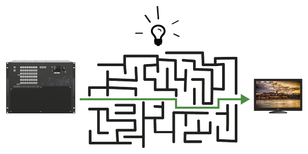
Lightware’s technical support team is always working hard to provide the fastest support possible. Our team’s response time is one of the best in the industry, and in the toughest of cases we can directly consult with the hardware or software engineer who designed the product to get the information from the most reliable source.
However, the troubleshooting process can be even faster… with your help.
There are certain pieces of information that push us in the right direction to find the root cause of the problem. If we receive most of this information in the first e-mail, or it is gathered at the time when you call us, then there is a pretty high chance that we will be able to respond with the final solution right away.
This information is the following:
▪Schematic (a pdf version is preferred, but a hand drawing is sufficient).
▪Serial number(s) of the device(s) (it is either printed somewhere on the box or you can query it in the Device Controller software or on the built-in website).
▪Firmware versions of the devices (please note that there may be multiple CPUs or controllers in the device and we need to know all of their firmware versions a screenshot is the best option).
▪Cable lengths and types.
▪Patch panels, gender changers or anything else in the signal path that can affect the transmission.
▪Signal type (resolution, refresh rate, color space, deep color).
▪Emulated EDID(s) (please save them as a file and send it to us).
▪Actions to take in order to re-create the problem (if we cannot reproduce the problem, it is hard for us to find the cause).
▪Photo or video about the problem (for example: "image noise" can mean many different things, it’s better if we see it too).
▪Error logs from the Device Controller software.
▪In the case of an Event Manager issue, the event file and/or backup file from the Device Controller software.
The more of the information above you can give us, the better. Please send this information to the Lightware Support Team (support@lightware.com) to speed up the troubleshooting process.
The following sections contain descriptions and useful technical information on how the devices work in the background. The content is based on experiences and cases we met in the practice. These sections help to understand features and technical standards like the following:
11.1.1. Understanding the EDID
The Extended Display Identification Data (EDID) is the passport of display devices (monitors, TV sets, projectors). It contains information about the capabilities of the display, such as supported resolutions, refresh rates (these are called Detailed Timings), the type and manufacturer of the display device, etc.
After connecting a source to a display (DVI, HDMI, DP), the source reads out the EDID to determine the resolution and refresh rate of the image to be transmitted.

EDID Communication
Most DVI computer displays have a 128-byte-long EDID structure. However, Digital Televisions and HDMI capable displays may have another 128 bytes, which is called E-EDID and is defined by CEA (Consumer Electronics Association). This extension contains information about additional Detailed Timings, audio capabilities, speaker allocation and HDMI capabilities. It is important to know that all HDMI capable devices must have CEA extension, but not all devices with CEA extension are HDMI capable.
Common Problems Related to EDID
Problem: “My system consists of the following: a computer, a Lightware device, a WUXGA (1920x1200) LCD monitor, and an SXGA (1280x1024) projector. I would like to see the same image on the monitor and the projector. What EDID should I choose on the Lightware device?”
Solution: If you want to see the image on both displays, you need to select the resolution of the smaller display (in this case SXGA), otherwise the smaller display may not show the higher resolution image.
Problem: “I have changed to a different EDID on an input port of the Lightware device to have a different resolution, but nothing happens.”
Solution: Some graphics cards and video sources read out the EDID only after power-up, and later they do not sense that the EDID has been changed. You need to restart your source to make it read out the EDID again.
11.1.2. Advanced EDID Management
Each DVI sink (e.g. monitors, projectors, plasma displays, etc...) must support the EDID data structure. Source BIOS and operating systems are likely to query the sink using DDC2B protocol to determine what pixel formats and interface are supported. DVI standard uses EDID data structure to identify the monitor type and capabilities. Most DVI sources (VGA cards, set top boxes, etc.) will output DVI signal after accepting the connected sink’s EDID information. In the case of EDID readout failure or missing EDID, the source will not output DVI video signal.
Lightware devices provide the Advanced EDID Management function that helps system integration. The built-in EDID Router can store and emulate factory pre-programmed- and User programmable EDIDs. The EDID of the attached monitors or projectors for each output are stored in a non-volatile memory. This way the EDID of a monitor is available when the monitor is unplugged or switched off.
Any EDID can be emulated on any input. An emulated EDID can be copied from the EDID router’s memory (static EDID emulation), or from the last attached monitor’s memory (dynamic EDID emulation). For example, the Lightware device can be set up to emulate a sink device, which is connected to one of the outputs. In this case, the EDID automatically changes if the monitor is replaced with another display device (as long as it has a valid EDID).
EDID is independently programmable for all inputs without affecting each other. All inputs have their own EDID circuit.
INFO:The user is not required to disconnect the video cable to change an EDID as opposed to other manufacturer’s products. EDID can be changed even if a source is connected to the input and powered ON.
INFO:When EDID has been changed, the router toggles the HOTPLUG signal for 2 seconds. Some sources do not sense this signal. In such cases, the source device must be restarted or powered OFF and ON again.
Lightware Visual Engineering is a legal HDCP adopter. Several functions have been developed that help solve HDCP related problems. Complex AV systems often have both HDCP and non-HDCP components. The matrix allows transmitting HDCP encrypted and unencrypted signals. The devices will be still HDCP compliant, as they will never output an encrypted signal to a non-HDCP compliant display device. If an encrypted signal is switched to a non-compliant output, a red screen alert or muted screen will appear.
11.2.1. Protected and Unprotected Content
Many video sources send HDCP protected signal if they detect that the sink is HDCP capable – even if the content is not copyrighted. This can cause trouble if an HDCP capable device is connected between the source and the display. In this case, the content cannot be viewed on non-HDCP capable displays and interfaces like event controllers. Rental and staging technicians often complain about certain laptops, which are always sending HDCP encrypted signals if the receiver device (display, matrix router, etc.) reports HDCP compliancy. Even through, HDCP encryption is not required all the time (e.g. computer desktop image), certain laptops still do that.
To avoid unnecessary HDCP encryption, Lightware introduced the HDCP enabling/disabling function: the HDCP capability can be disabled in the Lightware device. If HDCP is disabled, the connected source will detect that the sink is not HDCP capable, and turn off authentication.
11.2.2. Disable Unnecessary Encryption
HDCP Compliant Sink
All the devices are HDCP-compliant, no manual setting is required, both protected and unprotected contents are transmitted and displayed on the sink.

Not HDCP-compliant Sink 1.
Not-HDCP compliant sink is connected to the matrix. Some sources (e.g. computers) always send HDCP encrypted signals if the receiver device reports HDCP compliancy, however, HDCP encryption is not required all the time (e.g. computer desktop image). If HDCP is enabled in the matrix, the image will not be displayed on the sink.
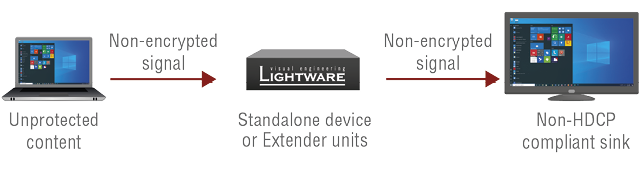
Setting the HDCP parameter to Auto on the output port and disable HDCP on the input port, the transmitted signal will not be encrypted if the content is not protected. Thus, non-HDCP compliant sinks will display non-encrypted signal.
Not HDCP-compliant Sink 2.
The layout is the same as in the previous case: non-HDCP compliant display device is connected to the matrix but the source would send protected content with encryption. If HDCP is enabled on the input port of the matrix, the source will send encrypted signal.

The sink is not HDCP compliant, thus it will not display the video signal (but blank/red/muted/etc. screen). If HDCP is disabled on the input port of the matrix, the source will not send the signal. The solution is to replace the display device to an HDCP-capable one.
11.2.3. HDCP v2.2
HDCP v2.2 is the latest evolution of copy protection. It is designed to create a secure connection between a source and a display. The 2.x version of HDCP is not a continuation of HDCPv1, and is rather a completely different link protection. One of the main differences is the number of the allowed devices within a closed A/V system: HDCP v2.2 allows 32 devices (HDCP v1.4 allows 128 devices). A further limit is that up to four level is allowed, which means the protected signal can be transmitted over at most four repeater/matrix/switcher devices. HDCP content protection is activated only if an active video stream is transmitted from the source to the display. The encryption is not activated without a video signal.
HDCP v2.2 standard allows applying a previous version of HDCP (e.g. HDCP v1.4) between the source and the display if the source device allows it. According to the standard if the image content is protected with HDCP, the highest supported content protection level has to be applied. However, if the highest level of protection is not justified by the source content, the level may be decreased to avoid compatibility problems; this case is determined by the source.
HDCP v2.2 Source and HDCP v1.4 Sink
In this case the signal of an HDCP v2.2 compliant source is switched to an HDCP v1.4 compliant sink device. The signal is encrypted with HDCP v2.2 on the input and encrypted with HDCP v1.4 on the output of the Lightware device. A lower level of encryption may be applied only if the source device/content allows it - according to the HDCP standard. In this case the HDCP setting on the input port has to be set to HDCP 1.4 and Depends on input on the output port.

HDCP v1.4 Source and HDCP v2.2 Sink
The example below is the reversal of the previous case. An HDCP v1.4 compliant source sends a signal with HDCP v1.4 encryption. The signal is switched to an HDCP v2.2 compliant sink device. In this case the outgoing signal has to be encrypted with the highest supported encryption level towards the sink, as the Lightware device and the sink are both HDCP v2.2 compliant. The HDCP v2.2 standard does not allow keeping the original HDCP v1.4 encryption level on the output.

What Kind of Signal Will be on the Output of the Lightware Device?
See the table below that summarizes the possible cases:
|
Incoming Signal |
HDCP v1.4 Compatible Sink |
HDCP v2.2. Compatible Sink |
|
HDCP v1.4 |
HDCP v1.4 |
HDCP v2.2 |
|
HDCP v2.2 (convertable)* |
HDCP v1.4 |
HDCP v2.2 |
|
HDCP v2.2 (not convertable)* |
Red screen |
HDCP v2.2 |
* Stream type 0: the video stream allows the conversation of the signal to apply a lower level of encryption.
** Stream type 1: the video stream does not allow the conversation of the signal.
11.3. Pixel Accurate Reclocking
Signal reclocking is an essential procedure in digital signal transmission. After passing the reclocking circuit, the signal becomes stable, jitter-free, and can be transmitted over more equipment like processors, or event controllers. Without reclocking, sparkles, noise, and jaggies appear on the image.
Lightware’s sophisticated Pixel Accurate Reclocking technology fixes more problems than general TMDS reclocking. It removes not only intra-pair skew, but inter-pair skew as well. The Pixel Accurate Reclocking circuit eliminates the following errors:
Intra-pair skew
Skew between the + and - wires within a differential wire pair (e.g. Data2- and Data2+). It’s caused by different wire lengths or slightly different wire construction (impedance mismatch) in the DVI cable. It results in jitter.

Inter-pair skew
Skew between two differential wire pairs in a cable. It is caused by different wire pair lengths or different number of twists in the DVI cable. Too much inter-pair skew results in color shift in the picture or sync loss.

Jitter
Signal instability in the time domain. The time difference between two signal transitions should be a fixed value, but noise and other effects cause variations.

Noise
Electromagnetic interference between other electronic devices such as mobile phones, motors, etc. and the DVI cable are coupled onto the signal. Too much noise results in increased jitter.

INFO:The colors of the wire pairs in the pictures are for illustration and do not represent the color of the actual wires inside the cable.
Tables, drawings, guides, technical details and the hashtag keyword list as follows:
12.1. Specification
INFO:Specificatios are subject to change without notice.
12.1.1. MX2M-FR24R
General
|
Compliance |
CE, UKCA |
|
EMC (emission) |
EN 55032:2015+A1:2020 |
|
EMC (immunity) |
EN 55035:2017+A11:2020 |
|
RoHS |
EN 63000:2018 |
|
Electrical safety |
EN 62368-1:2020 |
|
Laser safety |
EN 60825-1:2014+A11:2021 |
|
Warranty |
3 years |
|
Cooling |
5x built-in cooling fans |
|
Operating temperature |
0 to +50˚C (+32 to +122˚F) |
|
Storage temperature |
-30° to +80˚C (-22° to +176˚F) |
|
Operating humidity |
10% to 90%, non-condensing |
Power
|
Number of power drawer slots |
2 |
|
Appliable power drawers |
MX2M-PSU-500-F |
|
MX2M-PSU-1250-FP |
Enclosure
|
Rack mountable |
Yes |
|
Material |
1.5 mm steel |
|
Rack size |
8U high, 1 rack wide |
|
Dimensions in mm |
441W x 400D x 354.8H |
|
Dimmensions in inch |
17.4W x 15.7D x 14H |
|
Dimensions with rack ears and PSU drawers in mm |
483W x 473D x 354.8H |
|
Dimensions with rack ears and PSU drawers in inch |
19W x 18.6D x 14H |
|
Weight (frame only) |
15,9 kg (35.05 lbs) |
|
Weight (installed with two power supply units) |
24,9 kg (54.89 lbs) |
Control Ports
Ethernet Ports
|
Number of ports |
3 |
|
Connector type |
Neutrik etherCON RJ45 female connector |
|
Ethernet date rate |
10/100/1000Base-T, full duplex with autodetect |
|
Power over Ethernet (PoE) |
Not supported |
RS-232 Serial Port
|
Number of ports |
1 |
|
Connector type |
9-pole D-SUB female |
|
Baud rates |
Between 4800 and 115200 Baud |
|
Data bits |
8 or 9 |
|
Parity |
None / Odd / Even |
|
Stop bits |
1 / 1.5 / 2 |
USB Port
|
Number of ports |
1 |
|
Connector type |
USB mini-B type |
|
USB compliance |
USB 2.0 |
12.1.2. MX2M-PSU-500-F
General
|
Compliance |
CE, UKCA |
|
EMC (emission) |
EN 55032:2015+A1:2020 |
|
EMC (immunity) |
EN 55035:2017+A11:2020 |
|
RoHS |
EN 63000:2018 |
|
Electrical safety |
EN 62368-1:2020 |
|
Warranty |
3 years |
|
Cooling |
by cooling fan fitted in the frame |
|
Operating temperature |
0 to +50˚C (+32 to +122˚F) |
|
Storage temperature |
-40° to +85˚C (-40° to +185˚F) |
|
Operating humidity |
10% to 90%, non-condensing |
Power Adaptor
|
Supported power source |
100-240 V AC; 50/60 Hz |
|
Input voltage range |
90-264 VAC |
|
Input frequency range |
47-63 Hz |
|
Input AC current (typ) |
4.85 A |
|
Rated output current |
41.7 A @ 12 VDC |
|
AC power connector |
IEC C14 receptacle |
|
Nominal power |
500 W |
Enclosure
|
Hot-swappable |
Yes |
|
Dimensions in mm |
206W x 376D x 48H |
|
Dimensions in inch |
8.11W x 14.8D x 1.89H |
|
Weight |
3110 g (6.86 lbs) |
12.1.3. MX2M-PSU-1250-FP
General
|
Compliance |
CE, UKCA |
|
EMC (emission) |
EN 55032:2015+A1:2020 |
|
EMC (immunity) |
EN 55035:2017+A11:2020 |
|
RoHS |
EN 63000:2018 |
|
Electrical safety |
EN 62368-1:2020 |
|
Warranty |
3 years |
|
Cooling |
by cooling fan fitted in the frame |
|
Operating temperature |
0 to +50˚C (+32 to +122˚F) |
|
Storage temperature |
-40° to +85˚C (-40° to +185˚F) |
|
Operating humidity |
10% to 90%, non-condensing |
Power Adaptor
|
Supported power source |
100-240 V AC; 50/60 Hz |
|
Input voltage range |
90-264 VAC |
|
Input frequency range |
47-63 Hz |
|
Input AC current (typ) |
12.35 A |
|
Rated output current |
41.7 A @ 12 VDC, 15.7A @ 48 VDC |
|
AC power connector |
IEC C14 receptacle |
|
Nominal power |
1250 W |
Enclosure
|
Hot-swappable |
Yes |
|
Dimensions in mm |
206W x 376D x 48H |
|
Dimensions in inch |
8.11W x 14.8D x 1.89H |
|
Weight |
4480 g (9.87 lbs) |
12.1.4. MX2M-4HDMI20-IB
General
|
Compliance |
CE, UKCA |
|
EMC (emission) |
EN 55032:2015+A1:2020 |
|
EMC (immunity) |
EN 55035:2017+A11:2020 |
|
RoHS |
EN 63000:2018 |
|
Electrical safety |
EN 62368-1:2020 |
|
Warranty |
3 years |
|
Cooling |
passive |
|
Operating temperature |
0 to +50˚C (+32 to +122˚F) |
|
Storage temperature |
-40° to +85˚C (-40° to +185˚F) |
|
Operating humidity |
10% to 90%, non-condensing |
Enclosure
|
Material |
1.5 mm steel |
|
Dimensions in mm |
194,5W x 208,5D x 35,5H |
|
Dimmensions in inch |
17.4W x 15.7D x 14H |
|
Weight |
276 g (0.6 lbs) |
Video Inputs
|
Number of ports |
4 |
|
Connector type |
19-pole HDMI Type A receptacle |
|
AV standard |
DVI 1.0, HDMI 2.0 |
|
HDCP compliance |
HDCP 1.4 and HDCP 2.2 |
|
Color space |
RGB, YCbCr 4:4:4, YCbCr 4:2:2, YCbCr 4:2:0 |
|
Video delay |
0 frame |
|
Supported resolutions at 8 bits/color * |
up to 4096x2160@60Hz (4:4:4) up to 3840x2160@60Hz (4:4:4) |
|
Reclocking |
Pixel Accurate Reclocking |
|
3D support |
Yes |
|
Audio formats |
8 channel PCM DTS, DTS-HD Master Audio 7.1, WMA Pro Dolby Digital, Dolby Digital Plus, Dolby TrueHD, Dolby Atmos, Dolby Vision |
|
Input cable equalization |
Yes, +12dB fixed |
* All standard VESA, CEA and other custom resolutions up to 600MHz (HDMI2.0) are supported. If the pixel clock of the signal is above 340MHz, horizontal resolution cannot exceed 4096 pixels.
12.1.5. MX2M-DH-4DP12-IB
General
|
Compliance |
CE, UKCA |
|
EMC (emission) |
EN 55032:2015+A1:2020 |
|
EMC (immunity) |
EN 55035:2017+A11:2020 |
|
RoHS |
EN 63000:2018 |
|
Electrical safety |
EN 62368-1:2020 |
|
Warranty |
3 years |
|
Cooling |
passive |
|
Operating temperature |
0 to +50˚C (+32 to +122˚F) |
|
Storage temperature |
-40° to +85˚C (-40° to +185˚F) |
|
Operating humidity |
10% to 90%, non-condensing |
Enclosure
|
Material |
1.5 mm steel |
|
Dimensions in mm |
194,5W x 208,5D x 35,5H |
|
Dimmensions in inch |
17.4W x 15.7D x 14H |
|
Weight |
288 g (0.63 lbs) |
Video Inputs
|
Number of ports |
4 |
|
Connector type |
20-pole DisplayPort receptacle |
|
AV standard |
DP 1.2a |
|
HDCP compliance |
HDCP 1.4 and HDCP 2.2 |
|
Color space |
RGB, YCbCr 4:4:4, YCbCr 4:2:2, YCbCr 4:2:0 |
|
Video delay |
0 frame |
|
Supported resolutions at 8 bits/color * |
up to 4096x2160@60Hz (4:4:4) up to 3840x2160@60Hz (4:4:4) |
|
Reclocking |
Pixel Accurate Reclocking |
|
3D support |
Yes |
|
Audio formats |
8 channel PCM DTS, DTS-HD Master Audio 7.1, WMA Pro Dolby Digital, Dolby Digital Plus, Dolby TrueHD, Dolby Atmos, Dolby Vision |
* All standard VESA, CEA and other custom resolutions up to 600MHz (DP 1.2) are supported.
12.1.6. MX2M-4OPTJ-IB
General
|
Compliance |
CE, UKCA |
|
EMC (emission) |
EN 55032:2015+A1:2020 |
|
EMC (immunity) |
EN 55035:2017+A11:2020 |
|
RoHS |
EN 63000:2018 |
|
Electrical safety |
EN 62368-1:2020 |
|
Laser safety |
EN 60825-1:2014+A11:2021 |
|
Warranty |
3 years |
|
Cooling |
2x built-in cooling fans |
|
Operating temperature |
0 to +50˚C (+32 to +122˚F) |
|
Storage temperature |
-40° to +85˚C (-40° to +185˚F) |
|
Operating humidity |
10% to 90%, non-condensing |
Enclosure
|
Material |
1.5 mm steel |
|
Dimensions in mm |
194,5W x 208,5D x 35,5H |
|
Dimmensions in inch |
17.4W x 15.7D x 14H |
|
Weight |
340 g (0.74 lbs) |
Video Inputs
|
AV standard |
DVI 1.0, HDMI 2.0 |
|
HDCP compliance |
HDCP 1.4 and HDCP 2.2 |
|
Color space |
RGB, YCbCr 4:4:4, YCbCr 4:2:2, YCbCr 4:2:0 |
|
Video delay |
0 frame |
|
Supported resolutions at 8 bits/color * |
up to 4096x2160@60Hz (4:4:4) up to 3840x2160@60Hz (4:4:4) |
|
Reclocking |
Pixel Accurate Reclocking |
|
3D support |
Yes |
|
Audio formats |
8 channel PCM DTS, DTS-HD Master Audio 7.1, WMA Pro Dolby Digital, Dolby Digital Plus, Dolby TrueHD, Dolby Atmos, Dolby Vision |
|
Input cable equalization |
Yes, +12dB fixed |
* All standard VESA, CEA and other custom resolutions up to 600MHz (HDMI2.0) are supported. If the pixel clock of the signal is above 340MHz, horizontal resolution cannot exceed 4096 pixels.
Fiber Optical Ports
|
Number of ports |
4 |
|
Connector type |
SC simplex |
|
Fiber type |
50/125 SC multimode fiber |
|
Laser wavelengths |
High speed lane: 780, 800, 825, 850 nm Low speed lane: 910, 980 nm |
|
Compliance |
IEC/EN 60825-1:2014-05 Ed. 3.0; 21CFR Subchapter J Parts 1040.40 and 1040.11, except for deviations pursuant to Laser Notice No. 50 dated June 27, 2007 |
|
Transmitter output OMA (Optical Modulation Amplitude) |
-6.25 dBm (worst case) |
|
Receiver OMA (Optical Modulation Amplitude) sensitivity |
-14.25 dBm (worst case) |
|
Optical loss budget |
8 dBm (worst case) |
12.1.7. MX2M-4TPX-IB
General
|
Compliance |
CE, UKCA |
|
EMC (emission) |
EN 55032:2015+A1:2020 |
|
EMC (immunity) |
EN 55035:2017+A11:2020 |
|
RoHS |
EN 63000:2018 |
|
Electrical safety |
EN 62368-1:2020 |
|
Warranty |
3 years |
|
Cooling |
2x built-in cooling fans |
|
Operating temperature |
0 to +50˚C (+32 to +122˚F) |
|
Storage temperature |
-40° to +85˚C (-40° to +185˚F) |
|
Operating humidity |
10% to 90%, non-condensing |
Enclosure
|
Material |
1.5 mm steel |
|
Dimensions in mm |
194,5W x 208,5D x 35,5H |
|
Dimmensions in inch |
17.4W x 15.7D x 14H |
|
Weight |
340 g (0.74 lbs) |
Video Input
|
Number of ports |
4 |
|
Connector type |
RJ45 female connector |
|
Power over Ethernet (PoE) |
yes (IEEE 802.3af) |
|
Compliance |
AVX by SDVoE |
|
HDCP compliance |
HDCP 2.3 |
|
Transferred signals |
Video, Audio, RS-232, Infrared, Ethernet, USB K+M |
|
Color space |
RGB, YCbCr |
|
Video latency |
0 frame (five lines / under 8ms) |
|
Compression ratio |
1.4 to 1 * |
|
Supported resolutions at 8 bits/color ** |
up to 4096x2160@60Hz (4:4:4) up to 3840x2160@60Hz (4:4:4) |
|
Audio formats |
8 channel PCM DTS, DTS-HD Master Audio 7.1, WMA Pro Dolby Digital, Dolby Digital Plus, Dolby TrueHD, Dolby Atmos, Dolby Vision |
* Compression is applied only if the AV signal is above HDMI 1.4 standard.
** All standard VESA, CEA and other custom resolutions up to 600MHz (HDMI2.0) are supported. If the pixel clock of the signal is above 340MHz, horizontal resolution cannot exceed 4096 pixels.
12.1.8. MX2M-4HDMI20-OB
General
|
Compliance |
CE, UKCA |
|
EMC (emission) |
EN 55032:2015+A1:2020 |
|
EMC (immunity) |
EN 55035:2017+A11:2020 |
|
RoHS |
EN 63000:2018 |
|
Electrical safety |
EN 62368-1:2020 |
|
Warranty |
3 years |
|
Cooling |
passive |
|
Operating temperature |
0 to +50˚C (+32 to +122˚F) |
|
Storage temperature |
-40° to +85˚C (-40° to +185˚F) |
|
Operating humidity |
10% to 90%, non-condensing |
Enclosure
|
Material |
1.5 mm steel |
|
Dimensions in mm |
194,5W x 208,5D x 35,5H |
|
Dimmensions in inch |
17.4W x 15.7D x 14H |
|
Weight |
276 g (0.6 lbs) |
Video Outputs
|
A/V standard |
DVI 1.0, HDMI 2.0 |
|
HDCP compliance |
HDCP 1.4 and HDCP 2.2 |
|
Color space |
RGB, YCbCr 4:4:4, YCbCr 4:2:2, YCbCr 4:2:0 |
|
Video delay |
0 frame |
|
Supported resolutions at 8 bits/color * |
up to 4096x2160@60Hz (4:4:4) up to 3840x2160@60Hz (4:4:4) |
|
Reclocking |
Pixel Accurate Reclocking |
|
3D support |
Yes |
|
Audio formats |
8 channel PCM DTS, DTS-HD Master Audio 7.1, WMA Pro Dolby Digital, Dolby Digital Plus, Dolby TrueHD, Dolby Atmos, Dolby Vision |
|
Input cable equalization |
Yes, +12dB fixed |
* All standard VESA, CEA and other custom resolutions up to 600MHz (HDMI2.0) are supported. If the pixel clock of the signal is above 340MHz, horizontal resolution cannot exceed 4096 pixels.
12.1.9. MX2M-4OPTJ-OB
General
|
Compliance |
CE, UKCA |
|
EMC (emission) |
EN 55032:2015+A1:2020 |
|
EMC (immunity) |
EN 55035:2017+A11:2020 |
|
RoHS |
EN 63000:2018 |
|
Electrical safety |
EN 62368-1:2020 |
|
Laser safety |
EN 60825-1:2014+A11:2021 |
|
Warranty |
3 years |
|
Cooling |
2x built-in cooling fans |
|
Operating temperature |
0 to +50˚C (+32 to +122˚F) |
|
Storage temperature |
-40° to +85˚C (-40° to +185˚F) |
|
Operating humidity |
10% to 90%, non-condensing |
Enclosure
|
Material |
1.5 mm steel |
|
Dimensions in mm |
194,5W x 208,5D x 35,5H |
|
Dimmensions in inch |
17.4W x 15.7D x 14H |
|
Weight |
340 g (0,74 lbs) |
Video Outputs
|
AV standard |
DVI 1.0, HDMI 2.0 |
|
HDCP compliance |
HDCP 1.4 and HDCP 2.2 |
|
Color space |
RGB, YCbCr 4:4:4, YCbCr 4:2:2, YCbCr 4:2:0 |
|
Video delay |
0 frame |
|
Supported resolutions at 8 bits/color * |
up to 4096x2160@60Hz (4:4:4) up to 3840x2160@60Hz (4:4:4) |
|
Reclocking |
Pixel Accurate Reclocking |
|
3D support |
Yes |
|
Audio formats |
8 channel PCM DTS, DTS-HD Master Audio 7.1, WMA Pro Dolby Digital, Dolby Digital Plus, Dolby TrueHD, Dolby Atmos, Dolby Vision |
|
Input cable equalization |
Yes, +12dB fixed |
* All standard VESA, CEA and other custom resolutions up to 600MHz (HDMI2.0) are supported. If the pixel clock of the signal is above 340MHz, horizontal resolution cannot exceed 4096 pixels.
Fiber Optical Ports
|
Number of ports |
4 |
|
Connector type |
SC simplex |
|
Fiber type |
50/125 SC multimode fiber |
|
Laser wavelengths |
High speed lane: 780, 800, 825, 850 nm Low speed lane: 910, 980 nm |
|
Compliance |
IEC/EN 60825-1:2014-05 Ed. 3.0; 21CFR Subchapter J Parts 1040.40 and 1040.11, except for deviations pursuant to Laser Notice No. 50 dated June 27, 2007 |
|
Transmitter output OMA (Optical Modulation Amplitude) |
-6.25 dBm (worst case) |
|
Receiver OMA (Optical Modulation Amplitude) sensitivity |
-14.25 dBm (worst case) |
|
Optical loss budget |
8 dBm (worst case) |
12.1.10. MX2M-4TPX-OB
General
|
Compliance |
CE, UKCA |
|
EMC (emission) |
EN 55032:2015+A1:2020 |
|
EMC (immunity) |
EN 55035:2017+A11:2020 |
|
RoHS |
EN 63000:2018 |
|
Electrical safety |
EN 62368-1:2020 |
|
Warranty |
3 years |
|
Cooling |
passive |
|
Operating temperature |
0 to +50˚C (+32 to +122˚F) |
|
Storage temperature |
-40° to +85˚C (-40° to +185˚F) |
|
Operating humidity |
10% to 90%, non-condensing |
Enclosure
|
Material |
1.5 mm steel |
|
Dimensions in mm |
194,5W x 208,5D x 35,5H |
|
Dimmensions in inch |
17.4W x 15.7D x 14H |
|
Weight |
275 g (0.6 lbs) |
Video Output
|
Number of ports |
4 |
|
Connector type |
RJ45 female connector |
|
Power over Ethernet (PoE) |
yes (IEEE 802.3af) |
|
Compliance |
AVX by SDVoE |
|
HDCP compliance |
HDCP 2.3 |
|
Transferred signals |
Video, Audio, RS-232, Infrared, Ethernet, USB K+M |
|
Color space |
RGB, YCbCr |
|
Video latency |
0 frame (five lines / under 8ms) |
|
Compression ratio |
1.4 to 1 * |
|
Supported resolutions at 8 bits/color ** |
up to 4096x2160@60Hz (4:4:4) up to 3840x2160@60Hz (4:4:4) |
|
Audio formats |
8 channel PCM DTS, DTS-HD Master Audio 7.1, WMA Pro Dolby Digital, Dolby Digital Plus, Dolby TrueHD, Dolby Atmos, Dolby Vision |
* Compression is applied only if the AV signal is above HDMI 1.4 standard.
** All standard VESA, CEA and other custom resolutions up to 600MHz (HDMI2.0) are supported. If the pixel clock of the signal is above 340MHz, horizontal resolution cannot exceed 4096 pixels.
12.1.11. MX2M-AUX-DANTE-32CH
General
|
Compliance |
CE, UKCA |
|
EMC (emission) |
EN 55032:2015+A1:2020 |
|
EMC (immunity) |
EN 55035:2017+A11:2020 |
|
RoHS |
EN 63000:2018 |
|
Electrical safety |
EN 62368-1:2020 |
|
Warranty |
3 years |
|
Cooling |
passive |
|
Operating temperature |
0 to +50˚C (+32 to +122˚F) |
|
Storage temperature |
-40° to +85˚C (-40° to +185˚F) |
|
Operating humidity |
10% to 90%, non-condensing |
Enclosure
|
Material |
1.5 mm steel |
|
Dimensions in mm |
194,5W x 208,5D x 35,5H |
|
Dimmensions in inch |
17.4W x 15.7D x 14H |
|
Weight |
275 g (0.6 lbs) |
Audio Ports
|
Number of ports |
4 |
|
Connector type |
RJ45 female connector |
|
Audio formats |
Dante® or AES67 |
|
Supported channels |
2-channel stereo |
|
Sampling rates |
44.1, 48, 88.2, 96 kHz |
12.1.12. MX2M-AUX-8AUDIO
General
|
Compliance |
CE, UKCA |
|
EMC (emission) |
EN 55032:2015+A1:2020 |
|
EMC (immunity) |
EN 55035:2017+A11:2020 |
|
RoHS |
EN 63000:2018 |
|
Electrical safety |
EN 62368-1:2020 |
|
Warranty |
3 years |
|
Cooling |
passive |
|
Operating temperature |
0 to +50˚C (+32 to +122˚F) |
|
Storage temperature |
-40° to +85˚C (-40° to +185˚F) |
|
Operating humidity |
10% to 90%, non-condensing |
Enclosure
|
Material |
1.5 mm steel |
|
Dimensions in mm |
194,5W x 208,5D x 35,5H |
|
Dimmensions in inch |
17.4W x 15.7D x 14H |
|
Weight |
275 g (0.6 lbs) |
Audio Ports
|
Number of ports |
8 |
|
Connector type |
5-pole Phoenix connector |
|
Port type |
Configurable by jumper (Input / Output) |
Analog Audio Inputs
|
Audio formats |
2 channel PCM |
|
Sampling frequency |
48 kHz |
|
Maximum input level |
+4 dBu, 1.228 Vrms, 3.47 Vpp |
|
Signal transmission |
Balanced audio |
|
Balance |
-100 - 100 (0 = center) |
|
Gain |
-12 dB - 6 dB |
|
Volume |
-95 dB - 0 dB |
|
Frequency response |
20 Hz - 20 kHz |
|
THD + Noise |
-70 dB @ -1 dBFS |
|
Interchannel isolation |
83 dB |
Analog Audio Outputs
|
Audio formats |
2 channel PCM |
|
Supported sampling frequency |
44.1 kHz, 48 kHz, 88.2 kHz, 96 kHz |
|
Volume |
-78 dB - 0 dB |
|
Balance |
-100 - 100 (0 = center) |
|
Nominal Differential Output Level @ 0 dB Gain |
+4 dBu, 1.228 Vrms, 3.47 Vpp |
12.2. Switch Setup for Dante® Audio Signal Transmission
You can configure the QoS settings to ensure good system performance in a busy network. QoS (Quality of Service) refers to technology for prioritizing the transfer of specific data. By configuring the QoS settings recommended by Dante on a network switch, you can prioritize the transfer of Dante clock synchronization data and audio data over background data traffic. This will ensure good system performance when you need to transfer non-Dante data over the same network. QoS is required when using Dante in networks that have 100Mbps devices and is optional in networks with Gigabit devices. We recommend that QoS be enabled in all Dante networks in order to ensure proper operation under all possible conditions.
The table below shows how Dante uses various Diffserv Code Points (DSCP) packet priority values: *
|
Priority |
Usage |
DSCP Label |
Hex |
Decimal |
Binary |
|
High |
Time critical PTP events |
CS7 |
0x38 |
56 |
111000 |
|
Medium |
Audio, PTP |
EF |
0x2E |
46 |
101110 |
|
Low |
(reserved) |
CS1 |
0x08 |
8 |
001000 |
|
None |
Other traffic |
BestEffort |
0x00 |
0 |
000000 |
Green Ethernet in the Network
EEE (Energy Efficient Ethernet) is a technology that reduces switch power consumption during periods of low network traffic. It is also sometimes known as Green Ethernet and IEEE802.3az.
Although power management should be negotiated automatically in switches that support EEE, it is a relatively new technology, and some switches do not perform the negotiation properly. This may cause EEE to be enabled in Dante networks when it is not appropriate, resulting in poor synchronisation performance and occasional dropouts.
* source: https://www.audinate.com/learning/faqs
12.3. Applied Ports (Network Settings)
The following ports are necessary to pass via a network switch/firewall for a proper working between the device and the softwares:
|
Purpose/function |
Affected Lightware software |
Protocol |
Port nr. |
|
Firmware update TFTP |
LDU2 |
UDP |
69 |
|
UDP |
49990 |
||
|
UDP |
49995 |
||
|
Device Discovery |
LDC |
UDP |
224.0.0.251:5353 |
|
Remote IP |
LDC |
UDP |
230.76.87.82:37421 |
|
LW3 command protocol |
- |
TCP |
6107 |
|
HTTP port (built-in web server) |
- |
TCP |
80 |
12.4. Factory Default Settings
|
Parameter |
Setting/Value |
|
General settings |
|
|
Display backlight |
10 |
|
Jog dial rotary direction |
Clockwise (CW down) |
|
Control lock |
Disabled |
|
Output lock |
Disabled |
|
Network settings |
|
|
DHCP (dynamic IP address) |
Enabled |
|
LW3 control protocol port number |
6107 |
|
HTTP port number |
80 |
|
RS-232 port settings |
|
|
Configuration |
115200 BAUD 8N1 |
|
AV crosspoint settings |
|
|
Audio crosspoint |
I1 to all outputs |
|
Video crosspoint |
I1 to all outputs |
|
Video input port settings MX2M-4HDMI20-IB / MX2M-4OPTJ-IB / MX2M-4TPX-IB |
|
|
HDCP authentication |
Enabled |
|
Maximum enabled HDCP version |
HDCP 2.2 |
|
Color range |
Auto |
|
Hot plug detect |
Auto |
|
PoE enaled (only in case of TPX) |
false |
|
Video input port settings MX2M-DH-4DP12-IB |
|
|
HDCP authentication |
Enabled |
|
Maximum enabled HDCP version |
HDCP 2.2 |
|
Input lane count capability |
4 |
|
Maximum link rate availability |
HBR2 |
|
DP power sending |
Enabled |
|
Color space conversion |
Passthrough |
|
Color range |
Auto |
|
Hot plug detect |
Auto |
|
No sync screen (test pattern) mode |
Disabled |
|
Video output port settings MX2M-4HDMI20-OB / MX2M-4OPTJ-OB / MX2M-4TPX-OB |
|
|
HDCP mode |
Auto (depends on input) |
|
Power 5V mode |
On |
|
Signal type |
Auto |
|
Color space |
Passthrough |
|
Color depth |
8 bit per pixel |
|
Audio source |
HDMI |
|
PoE enaled (only in case of TPX) |
false |
|
Audio port settings MX2M-AUX-8AUDIO |
|
|
Port configuration |
Input |
|
Dante® port settings MX2M-AUX-DANTE-32CH |
|
|
IP address mode - Primary interface |
Unknown/query |
|
IP address mode - Secondary interface |
Unknown/query |
|
Analog audio input port properties |
|
|
Volume |
0.00 dB (100%) |
|
Balance |
0 (center) |
|
Gain |
0.00 dB |
|
Analog audio output port properties |
|
|
Volume |
0.00 dB (100%) |
|
Balance |
0 (center) |
12.5. Input/Output Port Numbering
12.5.1. Video Input/Output Port Numbering
The following drawing describes the video port numbering of the MX2M-FR24R matrix frame.

12.5.2. Audio Input Port Numbering
The following table shows the audio input numbering of the matrix. The audio port numbers are reserved and fixed for each I/O board slots because of the following reasons:
▪The I/O board models are built with different number of ports;
▪The boards can be installed to various board slots;
▪The AUX boards can also be installed to the slots that are dedicated to IB and OB boards.
|
Input port numbering on IB boards |
Input port numbering on AUX boards |
Layout of the matrix |
Input port numbering on IB boards |
Input port numbering on AUX boards |
|
|
Left side |
Right side |
||||

|
|||||
|
- |
I25-I40 |
- |
I41-I56 |
||
|
- |
I57-I72 |
- |
I73-I88 |
||
|
I1-I4 |
I89-I104 |
I5-I8 |
I105-I120 |
||
|
I9-I12 |
I121-I136 |
I13-I16 |
I137-I152 |
||
|
I17-I20 |
I153-I168 |
I21-I24 |
I169-I184 |
||
|
- |
I185-I200 |
- |
I201-I216 |
||
|
- |
I217-I232 |
- |
I233-I248 |
||
|
- |
I249-I264 |
- |
I265-I280 |
||
12.5.3. Audio Output Port Numbering
The following table shows the audio output numbering of the matrix. The audio port numbers are reserved and fixed for each I/O board slots because of the following reasons:
▪The I/O board models are built with different number of ports;
▪The boards can be installed to various board slots;
▪The AUX boards can also be installed to the slots that are dedicated to IB and OB boards.
|
Output port numbering on OB boards |
Output port numbering on AUX boards |
Layout of the matrix |
Output port numbering on OB boards |
Output port numbering on AUX boards |
|
|
Left side |
Right side |
||||
|
|
|||||
|
- |
O25-O40 |
- |
O41-O56 |
||
|
- |
O57-O72 |
- |
O73-O88 |
||
|
- |
O89-O104 |
- |
O105-O120 |
||
|
- |
O121-O136 |
- |
O137-O152 |
||
|
- |
O153-O168 |
- |
O169-O184 |
||
|
O1-O4 |
O185-O200 |
O5-O8 |
O201-O216 |
||
|
O9-O12 |
O217-O232 |
O13-O16 |
O233-O248 |
||
|
O17-O20 |
O249-O264 |
O21-O24 |
O265-O280 |
||
12.6.1. Fiber Optical Cable Distances
The following table shows the maximum allowed fiber optical cable distances.
Affected boards:
▪MX2M-4OPTJ-IB
▪MX2M-4OPTJ-OB
|
Resolution, Pixel clock rate |
OM1 |
OM2 |
OM3 |
OM4 |
|
1280x720p60 Hz |
800 m |
1000 m |
2500 m |
2500 m |
|
1920x1080p60 Hz |
500 m |
1000 m |
2500 m |
2500 m |
|
3840x2160p30 Hz (4k30 4:4:4) |
200 m |
600 m |
1500 m |
1500 m |
|
3840x2160p60 Hz (4k60 4:2:0) |
200 m |
600 m |
1500 m |
1500 m |
|
3840x2160p60 Hz (4k60 4:4:4) |
Not supported |
300 m |
600 m |
600 m |
|
4096x2160p60 Hz (DCI 4K60) |
Not supported |
300 m |
600 m |
600 m |
12.6.2. CATx Cable Distances for Dante
The following table shows the maximum allowed CATx cable distances.
Affected board:
▪MX2M-AUX-DANTE-32CH
|
Connection |
CAT5e |
CAT7e |
|
Connection between the auxiliary board and the network switch |
100 m |
|
12.6.3. CATx Cable Distances for TPX
The following table shows the maximum allowed CATx cable distances.
Affected board:
▪MX2M-4TPX-IB
▪MX2M-4TPX-OB
|
Resolution, Pixel clock rate |
CAT6e |
CAT7e |
||
|
AWG27 |
AWG23 |
AWG26 |
AWG23 |
|
|
3840x2160p30 Hz (4k30 4:4:4) |
85 m |
100 m |
90 m |
100 m |
|
3840x2160p60 Hz (4k60 4:4:4) |
85 m |
100 m |
80 m |
100 m |
Legend
D: DVI EDID
H: HDMI EDID
U: Universal EDID (supporting many common EDIDs)
4:2:0 : EDID with chroma color subsampling
4:4:4 : EDID without color subsampling
H2: HDMI2.0-compatible EDID
HDR: EDID with High Dynamic Range mode support
RB: Reduced blanking interval
PCM: With PCM audio support
ALL: All type of audio support (within the HDMI standard)
Please note that minor changes in the factory EDID list may be applied in further firmware versions.
|
Mem. |
Resolution |
Type |
|||
|
F1 |
640 x |
480 |
@ 60.00 |
Hz |
D |
|
F2 |
848 x |
480 |
@ 60.00 |
Hz |
D |
|
F3 |
800 x |
600 |
@ 60.32 |
Hz |
D |
|
F4 |
1024 x |
768 |
@ 60.00 |
Hz |
D |
|
F5 |
1280 x |
768 |
@ 50.00 |
Hz |
D |
|
F6 |
1280 x |
768 |
@ 59.94 |
Hz |
D |
|
F7 |
1280 x |
768 |
@ 75.00 |
Hz |
D |
|
F8 |
1360 x |
768 |
@ 60.02 |
Hz |
D |
|
F9 |
1280 x |
1024 |
@ 50.00 |
Hz |
D |
|
F10 |
1280 x |
1024 |
@ 60.02 |
Hz |
D |
|
F11 |
1280 x |
1024 |
@ 75.02 |
Hz |
D |
|
F12 |
1400 x |
1050 |
@ 50.00 |
Hz |
D |
|
F13 |
1400 x |
1050 |
@ 60.00 |
Hz |
D |
|
F14 |
1400 x |
1050 |
@ 75.00 |
Hz |
D |
|
F15 |
1680 x |
1050 |
@ 60.00 |
Hz |
D |
|
F16 |
1920 x |
1080 |
@ 50.00 |
Hz |
D |
|
F17 |
1920 x |
1080 |
@ 60.00 |
Hz |
D |
|
F18 |
2048 x |
1080 |
@ 50.00 |
Hz |
D |
|
F19 |
2048 x |
1080 |
@ 60.00 |
Hz |
D |
|
F20 |
1600 x |
1200 |
@ 50.00 |
Hz |
D |
|
F21 |
1600 x |
1200 |
@ 60.00 |
Hz |
D |
|
F22 |
1920 x |
1200 |
@ 50.00 |
Hz |
D |
|
F23 |
1920 x |
1200 |
@ 59.56 |
Hz |
D |
|
F24 |
2048 x |
1200 |
@ 59.96 |
Hz |
D |
|
F29 |
Universal DVI |
||||
|
F30 |
1440 x |
480 |
@ 60.05 |
Hz |
H |
|
F31 |
1440 x |
576 |
@ 50.08 |
Hz |
H |
|
F32 |
640 x |
480 |
@ 59.95 |
Hz |
H |
|
F33 |
720 x |
480 |
@ 59.94 |
Hz |
H |
|
F34 |
720 x |
576 |
@ 50.00 |
Hz |
H |
|
F35 |
1280 x |
720 |
@ 50.00 |
Hz |
H |
|
F36 |
1280 x |
720 |
@ 60.00 |
Hz |
H |
|
F37 |
1920 x |
1080 |
@ 50.04 |
Hz |
H |
|
F38 |
1920 x |
1080 |
@ 50.00 |
Hz |
H |
|
F39 |
1920 x |
1080 |
@ 60.05 |
Hz |
H |
|
F40 |
1920 x |
1080 |
@ 60.05 |
Hz |
H |
|
F41 |
1920 x |
1080 |
@ 24.00 |
Hz |
H |
|
F42 |
1920 x |
1080 |
@ 25.00 |
Hz |
H |
|
F43 |
1920 x |
1080 |
@ 30.00 |
Hz |
H |
|
F44 |
1920 x |
1080 |
@ 50.00 |
Hz |
H |
|
F45 |
1920 x |
1080 |
@ 60.00 |
Hz |
H |
|
F46 |
1920 x |
1080 |
@ 60.00 |
Hz |
H |
|
F47 |
Universal HDMI with PCM audio |
||||
|
F48 |
Universal HDMI with All audio |
||||
|
F49 |
Universal HDMI, all audio, deep color |
||||
|
F91 |
1024 x |
2400 |
@ 60.01 |
Hz |
H |
|
F98 |
1280 x |
720 |
@ 60.00 |
Hz |
H |
|
F99 |
1920 x |
1080 |
@ 60.00 |
Hz |
H |
|
F100 |
1024 x |
768 |
@ 60.00 |
Hz |
H |
|
F101 |
1280 x |
1024 |
@ 50.00 |
Hz |
H |
|
F102 |
1280 x |
1024 |
@ 60.02 |
Hz |
H |
|
F103 |
1280 x |
1024 |
@ 75.02 |
Hz |
H |
|
F104 |
1600 x |
1200 |
@ 50.00 |
Hz |
H |
|
F105 |
1600 x |
1200 |
@ 60.00 |
Hz |
H |
|
F106 |
1920 x |
1200 |
@ 59.56 |
Hz |
H |
|
F107 |
2560 x |
1440 |
@ 59.95 |
Hz |
H |
|
F108 |
2560 x |
1600 |
@ 59.86 |
Hz |
H |
|
F109 |
3840 x |
2400 |
@ 24.00 |
Hz |
H |
|
F110 |
3840 x |
2160 |
@ 24.00 |
Hz |
H |
|
F111 |
3840 x |
2160 |
@ 25.00 |
Hz |
H |
|
F112 |
3840 x |
2160 |
@ 30.00 |
Hz |
H |
|
F118 |
Universal HDMI, 4K, PCM audio |
||||
|
F119 |
Universal HDMI, 4K, all audio |
||||
|
F120 |
3840 x |
2160 |
@ 60.00 |
Hz |
H |
|
F121 |
1440 x |
1080 |
@ 59.91 |
Hz |
H |
|
F122 |
2560 x |
2048 |
@ 59.98 |
Hz |
H |
|
F123 |
1280 x |
800 |
@ 59.91 |
Hz |
H |
|
F124 |
1440 x |
900 |
@ 59.90 |
Hz |
H |
|
F125 |
1366 x |
768 |
@ 60.00 |
Hz |
H |
|
F126 |
1600 x |
900 |
@ 59.98 |
Hz |
H |
|
F127 |
2048 x |
1080 |
@ 60.00 |
Hz |
H |
|
F128 |
2560 x |
1080 |
@ 60.00 |
Hz |
H |
|
F129 |
3440 x |
1440 |
@ 24.99 |
Hz |
H |
|
F130 |
3440 x |
1440 |
@ 29.99 |
Hz |
H |
|
F131 |
4096 x |
2160 |
@ 25.00 |
Hz |
H |
|
F132 |
4096 x |
2160 |
@ 30.00 |
Hz |
H |
|
F133 |
4096 x |
2160 |
@ 60.00 |
Hz |
4:2:0 |
|
F134 |
3440 x |
1440 |
@ 23.99 |
Hz |
H |
|
F135 |
4096 x |
2160 |
@ 24.00 |
Hz |
H |
|
F136 |
3840 x |
2400 |
@ 29.99 |
Hz |
H |
|
F137 |
3840 x |
2160 |
@ 60.00 |
Hz |
H2 |
|
F138 |
3840 x |
2160 |
@ 50.00 |
Hz |
H2 |
|
F139 |
Universal HDMI 2.0, UHD, PCM audio |
||||
|
F140 |
Universal HDMI 2.0, UHD, all audio |
||||
|
F141 |
4096 x |
2160 |
@ 60.00 |
Hz |
4:4:4 |
|
F142 |
4096 x |
2160 |
@ 50.00 |
Hz |
4:4:4 |
|
F143 |
Universal HDMI 2.0, 4K, PCM audio |
||||
|
F144 |
Universal HDMI 2.0, 4K, all audio |
||||
|
F146 |
3840 x |
2160 |
@ 60.00 |
Hz |
HDR |
|
F147 |
3840 x |
2160 |
@ 60.00 |
Hz |
RB, PCM |
|
F148 |
3840 x |
2160 |
@ 60.00 |
Hz |
RB, ALL |
|
F150 |
5120 x |
1440 |
@ 29.97 |
Hz |
ALL |
|
F151 |
5120 x |
2160 |
@ 29.97 |
Hz |
ALL |
|
F152 |
5120 x |
2880 |
@ 29.97 |
Hz |
ALL |
|
F153 |
7680 x |
1080 |
@ 59.94 |
Hz |
ALL |
Inputs and outputs of audio devices are symmetric or asymmetric. The main advantage of the symmetric lines is the better protection against the noise, therefore they are widely used in the professional audio industry. Symmetric audio is most often referred to as balanced audio, as opposed to asymmetric, which is referred to as unbalanced audio. Ligthware products are usually built with 5-pole Phoenix connectors, so we would like to help users assemble their own audio cables. See the most common cases below.
ATTENTION!Symmetric and asymmetric lines can be linked with passive accessories (e.g. special cables), but in this case half of the line level is lost.
ATTENTION!There are numerous types of regularly used connector and cable types to connect audio devices. Please always make sure that a connector or cable fits your system before use.
ATTENTION!Never join the phase-inverted (negative, cold or -) poles (either right and left) to the ground or to each other on the output side, as this can damage the unit.
INFO:Use a galvanic isolation in case of a ground loop.
The Pinout of the 5-pole Phoenix Connector

Compatible Plug Type: Phoenix® Combicon series (3.5mm pitch, 5-pole), type: MC 1.5/5-ST-3.5.
From Unbalanced Output to Balanced Input
|
2 x 6.3 (1/4") TS - Phoenix |
2 x RCA - Phoenix |
3.5 (1/8") TRS - Phoenix |
||
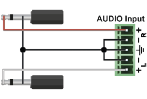
|

|
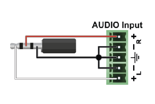
|
From Balanced Output to Unbalanced Input
|
Phoenix - 2 x 6.3 (1/4") TS |
Phoenix - 2 x RCA |
Phoenix - 3.5 (1/8") TRS |
||

|

|

|
From Balanced Output to Balanced Input
|
Phoenix - 2 x 6.3 (1/4") TRS |
Phoenix - 2 x XLR |
2 x 6.3 TRS (1/4") - Phoenix |
||

|

|

|
||
|
2 x XLR - Phoenix |
Phoenix - Phoenix |
|||

|
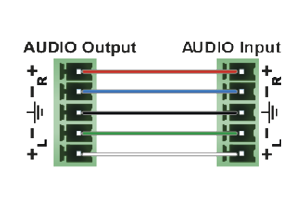
|
12.9.1. MX2M-FR24R
The following drawings present the physical dimensions of the MX2M-FR24R matrix frame. Dimensions are in mm.
Front View (1:4)

Top View (1:4)

Side View (1:4)

12.9.2. IB/OB Boards
The following drawings present the physical dimensions of the MX2M series input (IB) and output (OB) boards. Dimensions are in mm.
Front View (1:2)

Top View (1:2)

12.9.3. AUX Boards
The following drawings present the physical dimensions of the MX2M series auxiliary (AUX) boards. Dimensions are in mm.
Front View (1:2)

Top View (1:2)

12.10. Release Notes of the Firmware Packages
v1.6.1b1
Release date: 2023-12-14
Bugfix:
▪Fixed a bug that might have resulted in unstable signal detection on various input ports of the MX2M-4DP12-IB board.
v1.6.0b7
Release date: 2023-08-22
Bugfix:
▪Fixed a bug that resulted in the embedded audio being always indicated as present on the input of an MX2M-4HDMI20-IB or MX2M-4OPTJ-IB board by the graphical user interface.
▪Improved on the quality of the video output.
Known issue:
▪A switch in the audio crosspoint in the matrix results in an audio glitch on the output boards. Thus, audio switch is not seamless.
▪The CEC Controller button on the HDMI-4TPX-IB currently does not work.
▪The MX2M-4TPX-OB board might erroneously indicate that the video signal is a non-HDCP signal.
▪The image might get unstable for an extended amount of time on the output of a HDMI-TPX-RX107 device connected to the MX2M-4TPX-OB board when an audio crosspoint switch occurs on the respective output port in the matrix.
v1.5.0b9
Release date: 2023-06-02
New feature:
▪From this version on, the MX2M-FR24R supports the MX2M-4TPX-IB input board for receiving video, audio and auxiliary data from the HDMI-TPX extender family and from other SDVoE compatible transmitter devices.
Known issue:
▪The embedded audio is always indicated as present on the input of an MX2M-4HDMI20-IB or MX2M-4OPTJ-IB board by the graphical user interface. The corresponding LW3 property holds the right value, though,
▪DisplayID with version 1 is not supported by the MX2M modular matrix family.
▪Connecting multiple MX2M matrices through TPX links results in undefined control state in which neither the standalone LDC nor the embedded web works as expected.
▪There is a one-day difference between the actual date stored in the matrix and the actual date set through the graphical user interface.
v1.4.0b13
Release date: 2022-12-15
New feature:
▪From this version on, the MX2M-FR24R supports the MX2M-4TPX-OB output board for distributing video, audio and auxiliary data to the HDMI-TPX extender family and to other SDVoE compatible receiver devices.
Known issue:
▪No video signal data are shown on the TPX output when the respective output is not connected to a compatible receiver.
▪No audio information is available on TPX output ports.
v1.2.1b8
Release date: 2022-03-09
New feature:
▪From this version on, MX2M-4HDMI20-IB-E, MX2M-4HDMI20-OB-E, MX2M-4OPTJ-IB-E, MX2M-4OPTJ-OB-E, and MX2M-DH-4DP12-IB-E boards are supported.
Known issue:
▪Resetting a port on an MX2M-AUX-DANTE-32CH to its factory default settings has no effect.
▪The left and right channels of the stereo audio signal corresponding to a Dante input port on the MX2M-AUX-DANTE-32CH board are swapped.
v1.2.0b6
Release date: 2021-05-13
New feature:
▪From this version on, MX2M-4HDMI20-IB, MX2M-4HDMI20-OB, MX2M-4OPTJ-IB, MX2M-4OPTJ-OB, and MX2M-DH-4DP12-IB boards support DisplayID extension in the EDID.
Bugfix:
▪Fixed a bug that resulted in wrong board information being displayed in LDC after a firmware upgrade,
▪Fixed a bug that resulted in wrong nominal voltage values being reported for the MX2M-AUX-DANTE-32CH board on the Health pages of the graphical user interface.
▪Fixed a bug that required to manually alter the secondary mini crosspoint on the output of an MX2M-AUX-DANTE-32CH when the main crosspoint was modified.
▪Fixed a bug that resulted in the matrix not being restarted after restoring the configuration.
▪Fixed a bug that resulted in invalid backup file being uploaded to the matrix switcher.
▪Fixed a bug that caused the embedded web and the LDC application to generate an invalid backup file.
▪Fixed a bug that resulted in escape backslashes being added to the channel labels with opening or closing brackets on an MX2M-AUX-DANTE-32CH board.
▪Fixed a bug that prevented the channel label on an MX2M-AUX-DANTE-32CH board from being updated through the graphical user interface.
▪Fixed a bug that prevented the restore operation issued through the graphical user interface from being completed.
▪Added the Switch to all command to input ports of the MX2M-AUX-DANTE-32CH board on the graphical user interface.
Known issue:
▪If the matrix switcher is set up to use dynamic IP address allocation through DHCP and a different IP address is assigned to it by the DHCP server when the lease is renewed, the matrix switcher remains accessible through both the old and the new IP address.
▪Factory resetting the individual ports does not work. Moreover, after factory resetting an individual board might not reset some parameters.
▪The update of MX2M-4OPTJ-IB and MX2M-4OPTJ-OB boards might fail if the optical cables are connected during the update process. Should this be the case, unplugging the optical cables and restarting the matrix resolves the problem and the update gets finished successfully.
▪For video signals having a width of 4096 pixels or more, the video format returned is invalid. Such video signals are passed through the matrix switcher without any problem, it is just the format indication that is invalid.
▪The information on the color space of the video signal arriving at the input port might not get propagated to the output port. This results in invalid color space information in the output video signal. Manually triggering a hotplug event on the input restores the valid color space information on the output.
v1.1.0b13
Release date: 2021-02-15
New feature:
▪From this version on, the matrix firmware supports the MX2M-AUX-DANTE-32CH board.
▪From this version on, CEC is supported by the video IO boards.
Bugfix:
▪Fixed a bug that caused some sink devices (displays) to fail to synchronize to the video stream if they are fed through an HDMI20-OPTJ-RX90 from an MX2M-4OPTJ-OB board.
▪Fixed a bug that caused some ports on the MX2M-4OPTJ-OB output board not to function correctly.
Known issue:
▪The channel labels of the input and output ports on the MX2M-AUX-DANTE-32CH board are not reset when the Dante device corresponding to the respective board is factory reset from the Dante Controller.
▪The matrix might report invalid link status for the Primary and Secondary interfaces on an MX2M-AUX-DANTE-32CH board.
▪It might happen, that after switching on and off the input signal many times the input port on a video input board erroneously reports a valid HDMI signal.
▪When changing the source for an output port on the MX2M-AUX-DANTE-32CH board, the secondary mini crosspoint on the respective output also has to be altered to get the audio content corresponding to the new source out from the board.
▪The manual showing the usage of PriLinkType and SecLinkType properties erroneously states that the accepted values are numbers. Use the strings corresponding to the values to set the link type.
▪After a firmware upgrade, wrong board information is displayed in LDC. Restarting LDC resolves the issue.
▪Wrong nominal voltage values are reported for the MX2M-AUX-DANTE-32CH board on the Health pages of the graphical user interface.
v1.0.0b33
Release date: 2020-10-02
Known issue:
▪Color space conversion to YCbCr 4:2:2 on the output might result in invalid picture if the color space format of the incoming video signal is 4:2:0.
▪The audio embedded by a video output board (e.g. MX2M-4HDMI20-OB) into the output HDMI stream cannot be decoded by a less error resilient player device (like a HDMI receiver). The same audio is played back seamlessly and without any problem by a regular television.
▪The audio cannot be de-embedded from the input video on an MX2M-4HDMI20-IB or MX2M-4OPTJ-IB board when the source of the input video is an output board and the respective output is set to embed audio from the Audio layer.
▪It might take an unusually long time for some sink devices (displays) to synchronize to the video stream if they are fed through an HDMI20-OPTJ-RX90 from an MX2M-4OPTJ-OB board.
▪The output video stream might contain wrong audio channels when zero or one channel is selected for embedding in the output video stream on video output boards.
▪Presets created via the front panel are displayed as audio presets on the embedded web and in the LDC application.
▪The audio input ports on an MX2M-AUX-8AUDIO board cannot be muted.
This user's manual contains keywords with hashtags (#) to help you find the relevant information as quick as possible.
The format of the keywords is the following:
#<keyword>
The usage of the keywords: use the Search function (Ctrl+F / Cmd+F) of your PDF reader application, type the # (hashtag) character and the wished keyword.
The #new special keyword indicates a new feature/function that has just appeared in the latest firmware or software version.
Example
#dhcp
This keyword is placed at the DHCP (dynamic IP address) setting in the front panel operation, the Lightware Device Controller (LDC) and the LW3 programmer's reference section.
The following list contains all hashtag keywords placed in the document with a short description belonging to them. The list is in alphabetical order by the hashtag keywords.
|
Hashtag Keyword |
Description |
|
#advancedview |
Terminal (advanced view) window |
|
#aes67 |
Dante/AES67 audio related settings |
|
#analogaudio |
Analog audio related settings |
|
#audio |
Audio related settings |
|
#autotakemode |
Autotake mode |
|
#backup |
Configuration cloning (backup) |
|
#balance |
Balance (for analog audio) setting |
|
#builtinweb |
Built-in web |
|
#button |
Front panel button operations |
|
#cec |
CEC related settings |
|
#channelmapping |
Audio channel mapping setting |
|
#colorrange |
Color range setting |
|
#colorspace |
Color space converter related settings |
|
#controllock |
Front panel control lock |
|
#crosspoint |
Crosspoint switch setting |
|
#dante |
Dante/AES67 audio related settings |
|
#date |
Date setting |
|
#devicelabel |
Device label |
|
#dhcp |
Dynamic IP address (DHCP) setting |
|
#displayid |
DisplayID related settings |
|
#displayport |
DisplayPort related audio/video setting |
|
#dp |
DisplayPort related audio/video setting |
|
#dppower |
DisplayPort power send setting |
|
#edid |
EDID related settings |
|
#embedder |
Audio embedder (audio source) setting |
|
#factory |
Factory default settings |
|
#firmwareversion |
Firmware version query |
|
#framedetector |
Frame detector in LDC/built-in web |
|
#gain |
Gain (for analog audio) setting |
|
#hdcp |
HDCP-encryption related setting |
|
#hdmi |
HDMI related audio/video setting |
|
#health |
System monitoring (health) related information |
|
#hotplugdetect |
Hot plug detect setting |
|
#hpd |
Hot plug detect setting |
|
#ipaddress |
IP address related settings |
|
#label |
Device label |
|
#license |
License settings |
|
#linktraining |
DisplayPort link training setting |
|
#lock |
Port lock settings |
|
#log |
System log |
|
#mapping |
Audio channel mapping setting |
|
#mute |
Port mute setting |
|
#network |
Network (IP address) related settings |
|
#nosyncscreen |
Test pattern (no sync screen) settings |
|
#optj |
OPTJ related audio/video setting |
|
#outputlock |
Front panel output lock |
|
#poe |
PoE (Power over Ethernet) related settings |
|
#power5v |
Power 5V mode setting |
|
#preset |
Preset related settings |
|
#producttype |
Product type query |
|
#reboot |
Restarting the device |
|
#reset |
Restarting the device |
|
#restart |
Restarting the device |
|
#restore |
Configuration cloning (restore) |
|
#serialnumber |
Serial number query |
|
#softreset |
Software reseting of the device |
|
#status |
Status query |
|
#switch |
Crosspoint switch setting |
|
#systemmonitor |
System monitoring (health) related information |
|
#takemode |
Take mode |
|
#terminal |
Terminal (advanced view) window |
|
#testpattern |
Test pattern (no sync screen) settings |
|
#time |
Time setting |
|
#tpx |
TPX (SDVoE AVX) related settings |
|
#unlock |
Port unlock settings |
|
#unmute |
Port unmute setting |
|
#volume |
Volume (for analog audio) setting |
|
#web |
Built-in web |

12.12. Further Information
Limited Warranty Statement
1. Lightware Visual Engineering PLC (Lightware) warrants to all trade and end user customers that any Lightware product purchased will be free from manufacturing defects in both material and workmanship for three (3) years from purchase unless stated otherwise below. The warranty period will begin on the latest possible date where proof of purchase/delivery can be provided by the customer. In the event that no proof can be provided (empty ‘Date of purchase’ field or a copy of invoice), the warranty period will begin from the point of delivery from Lightware.
1.1. 25G and MODEX product series will be subject to a seven (7) year warranty period under the same terms as outlined in this document.
1.2. If during the first three (3) months of purchase, the customer is unhappy with any aspect of a Lightware product, Lightware will accept a return for full credit.
1.3. Any product that fails in the first six (6) months of the warranty period will automatically be eligible for replacement and advanced replacement where available. Any replacements provided will be warranted for the remainder of the original unit’s warranty period.
1.4. Product failures from six (6) months to the end of the warranty period will either be repaired or replaced at the discretion of Lightware. If Lightware chooses to replace the product, then the replacement will be warranted for the remainder of the original unit’s warranty period.
2. The above-stated warranty and procedures will not apply to any product that has been:
2.1. Modified, repaired or altered by anyone other than a certified Lightware engineer unless expressly agreed beforehand.
2.2. Used in any application other than that for which it was intended.
2.3. Subjected to any mechanical or electrical abuse or accidental damage.
2.4. Any costs incurred for repair/replacement of goods that fall into the above categories (2.1., 2.2., 2.3.) will be borne by the customer at a pre-agreed figure.
3. All products to be returned to Lightware require a return material authorization number (RMA) prior to shipment, and this number must be clearly marked on the box. If an RMA number is not obtained or is not clearly marked on the box, Lightware will refuse the shipment.
3.1. The customer will be responsible for in-bound and Lightware will be responsible for out-bound shipping costs.
3.2. Newly repaired or replaced products will be warranted to the end of the originally purchased product's warranty period.
Document Revision History
|
Rev. |
Release date |
Changes |
Editor |
|
1.0 |
13-08-2020 |
Initial version |
Tamas Forgacs |
|
... |
|||
|
1.6 |
04-10-2023 |
Fixed DP conversion mode information |
Tamas Forgacs |
|
1.7 |
21-12-2023 |
Specification updated |
Tamas Forgacs |
+36 1 255 3810
Lightware Visual Engineering PLC.
Peterdy 15, Budapest H-1071, Hungary
©2024 Lightware Visual Engineering. All rights reserved. All trademarks mentioned are the property of their respective owners. Specifications subject to change without notice.