Thank you for choosing Lightware’s VINX Video Network Extender devices. In the first chapter we would like to introduce the device by highlighting the most important features in the sections listed below:
1.1. Description
VINX-120-HDMI-ENC and VINX-110-HDMI-DEC are LAN-based Encoder/Decoder multimedia extenders to extend HDMI video from a local source to a remote sink. The Encoder and Decoder devices connect either via a direct CATx cable connection or through a Gigabit Ethernet Switch in between. The maximum delivery distance can reach up to 100 m with minimal latency and employing a quality, proprietary wavelet transform based image compression.
The maximum supported resolution is 3840 x 2160 @ 30Hz with 7.1 audio. The devices support both static and dynamic (DHCP) IP address settings. Pre-programmed factory EDID presets and user EDIDs are stored in the Encoder. DIP switches serve quick manual setting for device pairing over the network, a quick and easy installation method. Gap and bezel compensation can be adjusted for video walls. Scaling is available on the receiver side and videos can be freely cropped.
VINX AP-series
The VINX 'AP-series’ is the second generation of the VINX family. These products extend the features of the first generation with the following functions: VGA input port, Analog audio (de)embedding and transmission over SFP modules. Furthermore, the devices can be powered over Ethernet (PoE).
VINX-120AP-HDMI-ENC-DNT
This variant contains a special module that allows de-embedding the audio of the incoming HDMI signal and transmitting as a 2-channel Dante® or AES67 source via the extra RJ45 connector. See more details in the Dante® Audio Output Interface section.
Dante® is a registered trademark of Audinate Pty Ltd.
WP-VINX-110P-HDMI-ENC
The wall plate model of the VINX family offers multimedia extension of the same quality as the other models, with the added benefit of taking up less space and blending in more.
FP-VINX-series
The floor plate models have the same attributes as the wall plate model, while being compatible with several floor mounting boxes for easy and comfortable installation.
Compatible Devices
The VINX AP-series devices and the WP- and FP-VINX models are compatible with each other and the VINX-120-HDMI-ENC and VINX-110-HDMI-DEC (basic VINX) devices. Please note that certain features are not available when mixing VINX-AP and basic VINX devices:
|
Basic series |
AP series |
WP/FP series |
|
|
Video input port |
HDMI |
HDMI, VGA * |
HDMI |
|
Analog audio (de)embedding |
|
|
|
|
Return audio (mono) – in unicast mode |
|
|
|
|
Dante® or AES67 audio de-embedding |
|
** |
|
|
Network interface |
RJ45 |
RJ45, SFP |
RJ45 |
|
Powering modes |
local |
local, PoE |
local, PoE |
* VGA is available in VINX-210AP-HDMI-ENC model only.
** In VINX-120AP-HDMI-ENC-DNT model only.
See more details in the Model Comparison section.
Model Denomination

About the Serial Number
Lightware devices contain a label indicating the unique serial number of the product. The structure is the following:

1.2. Box Contents
The assembling of certain accessories can be found in the Mounting Options section
Desktop models
|
Supplied accessories |
Optional accessories |
|||||||||||

|

|

|

|
|

|

|

|

|

|

|
||
|
Encoder / Decoder device |
Safety and warranty info, QSG |
5V DC adaptor |
12 DC adaptor |
Mounting screws (m3x4) |
Infrared transmitter unit |
Infrared receiver unit |
VESA-100 compatible mounting adaptor |
UD-kit |
UD-kit double |
1U high rack shelf |
Powered rackmount cage (PRC-16-205) |
|
|
VINX-110-HDMI-DEC |
|
|
|
- |
(2 pcs.) |
- |
|
|
|
|
|
|
|
VINX-120-HDMI-ENC |
|
|
|
- |
(2 pcs.) |
|
- |
|
|
|
|
|
|
VINX-110AP-HDMI-DEC |
|
|
- |
|
(2 pcs.) |
- |
|
- |
- |
|
|
- |
|
VINX-210AP-HDMI-ENC |
|
|
- |
|
(2 pcs.) |
|
- |
- |
- |
|
|
- |
|
VINX-120AP-HDMI-ENC |
|
|
- |
|
(2 pcs.) |
|
- |
- |
- |
|
|
- |
|
VINX-120AP-HDMI-ENC-DNT |
|
|
- |
|
(2 pcs.) |
|
- |
- |
- |
|
|
- |
Wallplate Model
|
Supplied accessories |
Optional accessories |
||||||||||
|

|

|

|

|

|

|
|

|

|

|
|
|
Encoder device |
Safety and warranty info, QSG |
Fixing screws |
Mounting screws |
Phoenix Combicon 2-pole Connector |
12V DC adaptor |
Switch/outlet box (B225R) |
FP-VINX-110P-HDMI-ENC-MKM kit |
FP-VINX-110P-HDMI-ENC-MKS kit |
FP-VINX-110P-HDMI-ENC-GES4 kit |
FP-VINX-110P-HDMI-ENC-GES9 kit |
|
|
WP-VINX-110P-HDMI-ENC |
|
|
(4 pcs.) |
(4 pcs.) |
|
|
|
- |
- |
- |
- |
|
FP-VINX-110P-HDMI-ENC-MKM1 |
|
|
- |
- |
|
|
- |
|
- |
- |
- |
|
FP-VINX-110P-HDMI-ENC-MKS1 |
|
|
- |
- |
|
|
- |
- |
|
- |
- |
|
FP-VINX-110P-HDMI-ENC-GES41 |
|
|
- |
- |
|
|
- |
- |
- |
|
- |
|
FP-VINX-110P-HDMi-ENC-GES91 |
|
|
- |
- |
|
|
- |
- |
- |
- |
|
1In case of the FP-VINX models, the respective kits are supplied with the device.
|
Enclosure width |
Power supply input |
Inputs |
Outputs |
Control ports |
||||||||||||||||||||
|
1/4 RU |
1/2 RU |
5V DC |
12V DC |
PoE |
HDMI |
VGA |
AV input |
Analog audio |
Micro-phone |
HDMI |
AV output |
Dante® audio |
Analog audio |
RS-232 |
IR IN |
IR OUT |
USB type-A |
USB mini-B |
USB type-B |
Ethernet |
||||
|
D-Sub9 |
RJ12 |
|||||||||||||||||||||||
|
|
|
|
|
|
|
|
|

|
|
|
|
|
|
|
|
|
|

|
||||||
|
VINX- |
|
- |
|
- |
- |
|
- |
- |
- |
- |
- |
|
|
- |
- |
- |
- |
|
- |
|
- |
|
- |
- |
|
VINX- |
|
- |
|
- |
- |
- |
- |
|
- |
- |
- |
|
- |
- |
- |
- |
- |
|
|
- |
|
- |
- |
- |
|
VINX- |
- |
|
- |
|
|
|
- |
- |
- |
|
- |
|
|
|
- |
|
(female) |
- |
- |
|
- |
- |
|
- |
|
VINX- |
- |
|
- |
|
|
|
- |
- |
- |
|
- |
|
|
|
|
|
(female) |
- |
- |
|
- |
- |
|
- |
|
VINX- |
- |
|
- |
|
|
|
|
- |
- |
|
- |
- |
|
|
- |
|
(female) |
- |
- |
|
- |
- |
|
- |
|
VINX- |
- |
|
- |
|
|
- |
- |
|
|
- |
|
|
- |
- |
- |
|
(male)( |
- |
|
- |
|
- |
- |
- |
|
WP-VINX-110P-HDMI-ENC |
- |
- |
- |
|
|
|
- |
- |
- |
- |
- |
- |
- |
- |
- |
- |
- |
- |
- |
- |
- |
- |
|
|
|
FP-VINX-110P-HDMI-ENC-MKM |
- |
- |
- |
|
|
|
- |
- |
- |
- |
- |
- |
- |
- |
- |
- |
- |
- |
- |
- |
- |
- |
|
|
|
FP-VINX-110P-HDMI-ENC-MKS |
- |
- |
- |
|
|
|
- |
- |
- |
- |
- |
- |
- |
- |
- |
- |
- |
- |
- |
- |
- |
- |
|
|
|
FP-VINX-110P-HDMI-ENC-GES4 |
- |
- |
- |
|
|
|
- |
- |
- |
- |
- |
- |
- |
- |
- |
- |
- |
- |
- |
- |
- |
- |
|
|
|
FP-VINX-110P-HDMI-ENC-GES9 |
- |
- |
- |
|
|
|
- |
- |
- |
- |
- |
- |
- |
- |
- |
- |
- |
- |
- |
- |
- |
- |
|
|
1.4. Features of the Device

|
Video Wall Application |
|
The VINX devices can be arranged to a Video wall of up to 8x8 Display devices. The displayed video can be the same on each display, one image enlarged to all the sinks, or the mixture of these. |
|

|
Supporting 4K Resolution |
|
Up to HDMI 2.0 4K 2160p@60Hz 4:2:0 video input or 3840 x 2160 @ 30Hz resolution over a 1 Gigabit network with very low latency. |
|

|
3D Signal Support |
|
The extenders support the transmission of 3D content in 'Side-by-side' and 'Top-to-bottom' modes. |
|

|
Advanced EDID Management |
|
The user can emulate any EDID on the inputs independently, read out and store any attached monitor's EDID in the User memory locations, upload and download EDID files. |
|

|
Local HDMI Output |
|
A display device can be connected to the Encoder for local signal checking. The port carries the same video as the transmitted signal. |
|

|
Frame Detector and Signal Analysis |
|
The exact video and audio signal formats can be determined, such as timing, frequencies, scan mode, HDCP encryption, color range, color space and audio sample rate. |
|

|
Image Adjustment |
|
The extended video can be rotated or flipped at the Decoder side. Scaling is available at the Decoder side and videos can be freely cropped. |
|

|
Built-in Website |
|
Easy access from a web browser to control and configure the devices – even with a mobile device. |
|

|
USB Extension |
|
KVM extension for USB HID (Human Interface Devices, e.g. keyboard, mouse, presenter) and Mass Storage devices (Flash drive, Hard drive). |
|

|
Serial Data Transmission |
|
Transparent serial data transmission is available between the endpoints: Encoder and Decoder devices. |
1.5. Further Features of the AP-series
DIFFERENCE:The features mentioned below refer to the VINX-110AP-HDMI-DEC, VINX-120AP-HDMI-ENC and VINX-210AP-HDMI-ENC models only.
DIFFERENCE:The Remote Power (PoE) feature can also be found in the WP-VINX-110P-HDMI-ENC and the FP-VINX-series models.

|
Analog Video Support |
|
The extra VGA input port allows connecting analog video, which is converted to digital signal. |
|

|
Analog Audio Support |
|
External analog audio signal can embedded in the video stream at the Encoder side, and can be de-embedded at the Decoder side. |
|

|
SFP Module Support |
|
The devices can be connected to the network switch over SFP modules. |
|

|
Remote Power (PoE) |
|
The devices can be Powered over Ethernet (according to IEEE 802.3af) by a compatible power source equipment. |
|

|
Return Audio for a Microphone |
|
Mono input port for a microphone from the Decoder towards the Encoder when the extender-pair is used in Unicast mode. Includes a 20 dB gain in the signal path. |
|

|
Dante® or AES67 Audio De-embedding (VINX-120AP-HDMI-ENC-DNT only) |
|
The audio of the HDMI signal can be transmitted as a 2-channel Dante® or AES67 source over the dedicated RJ45 connector. |
1.6. Typical Applications

Video Wall Application (Multicast Mode)

Simple Signal Extension (Unicast Mode)
The following sections are about the physical structure of the device, input/output ports, connectors, status LEDs and front panel button functions.
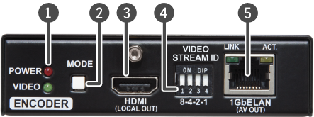
Front and Rear View

|
|
Status LEDs |
See the Front Panel LEDs section. |
|
|
Mode Button |
Short press: switching between Video and Graphics modes. Long press (more, than 10 seconds): reset to factory default settings.* |
|
|
HDMI Output Port |
Forwarding the same Audio / Video content as the AV Output Port. |
|
|
DIP Switch |
Linking Encoder and Decoder devices; for more information see the DIP Switch section. |
|
|
AV Output Port |
RJ45 connector for outgoing AV signal to the Decoder device or Network switch. Applied cable shall be max. 100 m (CAT5 or CAT7). |
|
|
DC 5V Input |
5V DC input for local power supply. |
|
|
RS-232 Port |
RJ12 connector for transparent serial communication (point-to-point or point-to-multi point). |
|
|
USB Port |
Mini B-type connector for USB pass-through (IP KVM) application. |
|
|
HDMI Input Port |
Video port for DVI or HDMI signal. |
|
|
IR Output Port |
IR signal output connector (for 3.5 mm Jack, 3-pole, TRS plug). |


* From firmware version v3.3.1, factory defaults may only be called this way for 90 seconds after booting up.
WARNING!Always use the supplied 5V power adaptor. Warranty void if damage occurs due to use of a different power source.
Front and Rear View


|
|
Status LEDs |
See the Front Panel LEDs section. |
|
|
Connect Button |
Short press: acquire USB connection (this is required only in Multicast mode) Long press (more than 10 seconds): reset to factory default settings.* |
|
|
HDMI Output Port |
HDMI output to a sink device. |
|
|
DIP Switch |
Linking Encoder and Decoder devices; for more information, see the DIP Switch section. |
|
|
AV Input Port |
RJ45 connector for incoming AV signal from the Encoder device or Network switch. Applied cable shall be max. 100 m (CAT5 or CAT7). |
|
|
DC 5V Input |
5V DC input for local power supply. |
|
|
RS-232 Port |
RJ12 connector for transparent serial communication (point-to-point or point-to-multi point). |
|
|
USB Ports |
USB 1.1 and 2.0 compatible A-type ports for transmitting USB HID and mass storage devices. USB 1.1 port can be used for changing the video stream by a keyboard, see the Keyboard Shortcuts section. |
|
|
IR Input Port |
IR signal input connector (for 3.5 mm Jack, 3-pole, TRS plug). |

* From firmware version v3.3.1, factory defaults may only be called this way for 90 seconds after booting up.
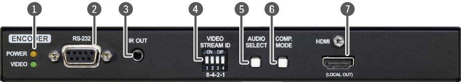
2.3. VINX-120AP-HDMI-ENC
Front View

|
|
Status LEDs |
See the Front Panel LEDs section. |
|
|
RS-232 Port |
D-SUB9 connector for transparent serial communication (point-to-point or point-to-multi point). |
|
|
IR Output Port |
IR signal output connector (for 3.5 mm Jack, 3-pole, TRS plug). |
|
|
DIP Switch |
Linking Encoder and Decoder devices (HW setting). |
|
|
Audio Select button |
Press the button to toggle between the following modes:
|
|
|
Compression Mode Button |
Short press: switching between the Video and Graphics modes. Long press (more than 10 seconds): reset to factory default settings.* |
|
|
HDMI Output |
For a local sink device (mirrored from the AV output). |

* From firmware version v3.3.1, factory defaults may only be called this way for 90 seconds after booting up.
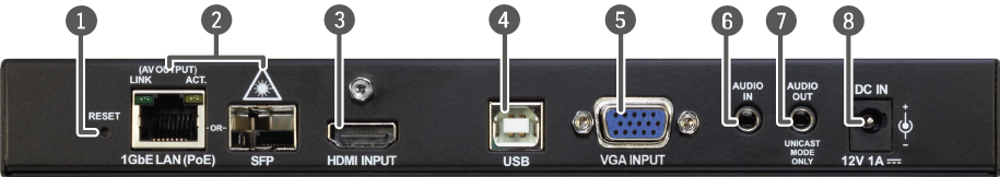
Rear View

|
|
Reset Button |
Reboots the device. |
|
|
AV Input Ports |
RJ45 connector and slot for an SFP module. One at a time is available for receiving an AV signal. Applied cable shall be max. 100 m (CAT5 or CAT7) in case of RJ45. Please note that SFP module is not supplied with the device. |
|
|
HDMI Input Port |
Video port for DVI or HDMI signal. |
|
|
USB Port |
B-Type connector for USB pass-through application (e.g. for connecting the Encoder to a computer). |
|
|
Audio Input Port |
For unbalanced analog audio signal. |
|
|
Audio Output Port |
Presenting the audio signal coming from the Audio input port of the connected Encoder. This feature is available only in Unicast mode, and if the Analog audio input is selected as an audio source on the Encoder. |
|
|
DC 12V Input |
12V DC input for local power supply. |
2.4. VINX-120AP-HDMI-ENC-DNT
Front View
|
|
Status LEDs |
See the Front Panel LEDs section. |
|
|
RS-232 Port |
D-SUB9 connector for transparent serial communication (point-to-point or point-to-multi point). |
|
|
IR Output Port |
IR signal output connector (for 3.5 mm Jack, 3-pole, TRS plug). |
|
|
DIP Switch |
Linking Encoder and Decoder devices (HW setting). |
|
|
Audio Select button |
Press the button to toggle between the following modes:
|
|
|
Compression Mode Button |
Short press: switching between the Video and Graphics modes. Long press (more than 10 seconds): reset to factory default settings.* |
|
|
HDMI Output |
For a local sink device (mirrored from the AV output). |
* From firmware version v3.3.1, factory defaults may only be called this way for 90 seconds after booting up.
Rear View

|
|
Dante® Audio Output |
RJ45 connector for de-embedding the HDMI audio, which can be transmitted as a 2-channel Dante® or AES67 source. Applied cable shall be max. 100 m (CAT5 or CAT7). |
|
|
Reset Button |
Reboots the device. |
|
|
AV Input Ports |
RJ45 connector and slot for an SFP module. One at a time is available for receiving an AV signal. Applied cable shall be max. 100 m (CAT5 or CAT7) in case of RJ45. Please note that SFP module is not supplied with the device. |
|
|
HDMI Input Port |
Video port for DVI or HDMI signal. |
|
|
USB Port |
B-Type connector for USB pass-through application (e.g. for connecting the Encoder to a computer). |
|
|
Audio Input Port |
For unbalanced analog audio signal. |
|
|
Audio Output Port |
Presenting the audio signal coming from the Audio input port of the connected Encoder. This feature is available only in Unicast mode, and if the Analog audio input is selected as an audio source on the Encoder. |
|
|
DC 12V Input |
12V DC input for local power supply. |
2.5. VINX-210AP-HDMI-ENC
Front View

|
|
Status LEDs |
See the Front Panel LEDs section. |
|
|
RS-232 Port |
D-SUB9 connector for transparent serial communication (point-to-point or point-to-multi point). |
|
|
IR Output Port |
IR signal output connector (for 3.5 mm Jack, 3-pole, TRS plug). |
|
|
DIP Switch |
Linking Encoder and Decoder devices (HW setting). |
|
|
AV Select Button |
Press the button to toggle between the following modes:
See more details in the Front Panel Buttons section. |
|
|
Compression Mode Button |
Short press: switching between the Video and Graphics modes. Long press (more than 10 seconds): reset to factory default settings.* |

* From firmware version v3.3.1, factory defaults may only be called this way for 90 seconds after booting up.
Rear View
|
|
Reset Button |
Reboots the device. |
|
|
AV Input Ports |
RJ45 connector and slot for an SFP module. One at a time is available for receiving an AV signal. Applied cable shall be max. 100 m (CAT5 or CAT7) in case of RJ45. Please note that SFP module is not supplied with the device. |
|
|
HDMI Input Port |
Video port for DVI or HDMI signal. |
|
|
USB Port |
B-Type connector for USB pass-through application (e.g. for connecting the Encoder to a computer). |
|
|
VGA Input Port |
Video port for analog VGA signal on VINX-120AP-HDMI-ENC. |
|
|
Audio Input Port |
For unbalanced analog audio signal. |
|
|
Audio Output Port |
Presenting the audio signal coming from the Mic in input port of the connected Decoder. This feature is available only in Unicast mode, and if the Analog audio input is selected as an audio source on the Encoder. |
|
|
DC 12V Input |
12V DC input for local power supply. |
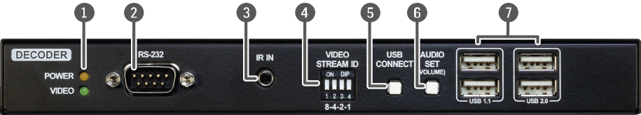
2.6. VINX-110AP-HDMI-DEC
Front View
|
|
Status LEDs |
See the Front Panel LEDs section. |
|
|
RS-232 Port |
D-SUB9 connector for transparent serial communication (point-to-point or point-to-multi point). |
|
|
IR Input Port |
IR signal input connector (for 3.5 mm Jack, 3-pole, TRS plug). |
|
|
DIP Switch |
Linking Encoder and Decoder devices (HW setting). |
|
|
USB Connect Button |
Short press: acquire USB connection (this is required only in Multicast mode). Long press (more than 10 seconds): reset to factory default settings. |
|
|
Audio Set Button |
Short press: the analog audio output volume is increased by 10%. Long press (more than 5 seconds): the analog audio output volume is set to 0%. |
|
|
USB Ports |
USB 1.1 and 2.0 compatible A-type ports for transmitting USB HID and mass storage devices. USB 1.1 port can be used for changing the video stream by a keyboard, see the Keyboard Shortcuts section. |
* From firmware version v3.3.1, factory defaults may only be called this way for 90 seconds after booting up.
Rear View

|
|
Reset Button |
Reboots the device. |
|
|
AV Input Ports |
RJ45 connector and slot for an SFP module. One at a time is available for receiving an AV signal. Applied cable shall be max. 100 m (CAT5 or CAT7) in case of RJ45. Please note that SFP module is not supplied with the device. |
|
|
HDMI Output |
HDMI output to a sink device on VINX-120AP-HDMI-DEC. |
|
|
MIC Input Port |
Mono input port for a microphone including +20 dB gain in the signal path. |
|
|
Audio Output Port |
Presenting the audio signal coming from the Audio input port of the connected Encoder. |
|
|
DC 12V Input |
12V DC input for local power supply. |
WARNING!The microphone input port applies a fixed bias to feed the connected electret (condenser) microphone. Thus, it is not suitable for dynamic microphones that do not contain isolation or an impedance matching transformer. (Danger of damage to the microphone.)
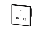
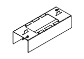
2.7. WP-VINX-110P-HDMI-ENC, FP-VINX-series
Front view Side view


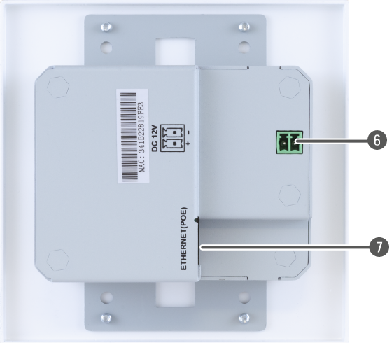
Rear view
|
|
Video signal status LED |
The LED gives immediate feedback about the current video signal status of the device. |
||
|
|
off |
There is no network connection. |
||
|
blinking (green) 
|
The device is connected to a network, but there is no video stream in progress. |
|||
|
on 
|
The device is connected to a network and there is video streaming in progress. |
|||
|
|
Power status LED |
The LED gives immediate feedback about the current power status on the device. |
||
|
|
off |
The device is not powered. |
||
|
|
blinking (red) |
The device is booting. |
||
|
|
on |
The device is powered on. |
||
|
|
USB port |
B-Type connector for USB pass-through application (e.g. for connecting the Encoder to a computer). |
||
|
|
Reset button |
Reboots the device. |
||
|
|
HDMI input port |
Port for DVI or HDMI video signal. |
||
|
|
DC input port |
12V DC input connector for local powering. |
||
|
|
Ethernet port |
Locking RJ45 connector for Ethernet connection. Can also be used to power the device remotely over Ethernet (PoE). |
||


INFO:The FP-VINX-series has the same setup, only the front panel differs.
DIFFERENCE:From firmware verison v3.5.1 the Video and Power status LEDs will blink together alternately when factory default settings are called.
INFO:Even if the colors of the LEDs in the devices are different, the functions are the same.
POWER LED
▪OFF: the device is not powered.
▪BLINKING: booting is in progress.
▪ON: the device is powered on.
VIDEO LED
▪OFF: there is no network connection.
▪BLINKING: the device is connected to a network, but there is no video stream in progress.
▪ON: the device is connected to a network and video stream is in progress.
USB LED (only in Decoders)
▪OFF: there is no USB transmission between the Encoder and the Decoder.
▪ON: the USB transmission is active between the Encoder and the Decoder.
POWER and VIDEO LEDs
▪BLINKING together: there is a Video Stream ID clash in the network, e.g. another Encoder is set to the same Video Stream ID. (only in Encoders)
▪BLINKING alternately: the device enters manufacturing mode when calling factory default settings.
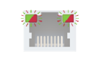
2.9. RJ45 LEDs
AV In/Out
|
Left LED, Green |
Right LED, Yellow |
|
|
|
Link |
Activity |
.png)
Dante® Audio Out
|
LED state |
Left LED |
Right LED |
Function |

|
Off |
Off |
No power |

|
Solid green |
Solid red |
Dante is booting |

|
Blinking green |
Solid green |
Slave with sync (normal operation) |

|
Blinking green |
Blinking green |
Clock master (normal operation) |

|
Blinking green |
Blinking red |
Acquiring clock sync (normal operation) |
|
Alternating red/green |
Alternating red/green |
Identify (blinking for 6 seconds) |

|
Blinking red |
Blinking red |
Dante fail safe |

|
Blinking amber |
Blinking amber |
Device is upgrading |
2.10.1.
Audio Select Button #button

Toggle between the following modes:

Auto: the Analog audio input port is selected when a plug is connected.
Mode and Compression Mode Buttons
▪Short press: switching between the Movie and Graphics modes.

▪Long press (more than 10 seconds): reset to factory default settings.
ATTENTION!From firmware version v3.3.1, factory defaults may only be called this way for 90 seconds after booting up.
When the network bandwidth is not enough to transmit the video signal, the following modes are available in the Encoder:
▪Movie mode (Lower image quality @ Less bandwidth): The image quality is adjusted to the available bandwidth. If the bandwidth is decreased, the image quality will be lower, but the video streaming will be continuous.
▪Graphics mode (Best image quality @ High bandwidth): The image quality is kept at a high level. If the bandwidth is decreased, the image quality does not change, but frame drop may appear.
The setting takes effect when the available bandwidth is less than required.
AV Select Button
Toggle between the following modes:


▪Auto mode: the first connected source shall remain active as long as signal is present on the respective input. If sync is lost for at least 3 seconds, it will be switched over to the other source. No automatic switch back to the original input takes place when the signal is restored.

Connect and USB Connect Buttons
When the button is pressed for less than ten seconds, the USB connection is acquired. This is necessary only in Multicast mode; when Unicast mode is active, the assignment is arranged automatically.
Audio Set Button

▪Short press: the analog audio output volume is increased by 10%.
▪Long press (more than 5 seconds): the analog audio output volume is set to 0%.
2.10.2. WP/FP models
Reset Button
▪Short press: reboots the device.
▪Long press (more than 10 seconds): reset to factory default settings.
ATTENTION!From firmware version v3.4.0, factory defaults may only be called this way for 90 seconds after booting up.
DIFFERENCE:The WP-VINX-110P-HDMI-ENC model does not have a DIP switch, its Video Stream ID can only be set in the LDC or in the Built-In Web.
The DIP switch can be used to set the Video Stream ID manually (HW setting). The interpretation of the DIP switch values can be found in the DIP Switch States section; please see the examples below:
|
DIP Switch State |
Video Stream ID |
/SYS/MB/GPIO.DipSwitch value |
|
|
Set by |
Value |
||

|
SW setting |
see the built-in web |
0x0 |

|
HW setting |
1 |
0x1 |

|
HW setting |
8 |
0x8 |
INFO:The HW setting of the DIP switch allows setting the Video Stream ID from 1 to 15. Higher Video Stream IDs (up to as much as 9999) can only be set using the Lightware Device Controller or the built-in-web.
#led #dipswitch #videostreamid #streamid
This chapter is about the installation of the device and connecting to other appliances, also presenting the mounting options and further assembly steps.
WARNING!For fixing the device to a Rack shelf, use the screws supplied with the extender. Longer screws may touch internal parts and harm the device.
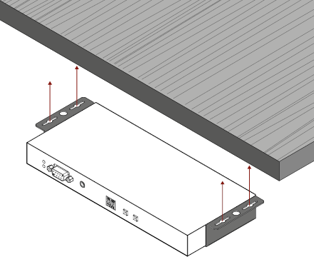
3.1.1. VESA100 Mounting Adapter for Extenders
DIFFERENCE:VESA100 Mounting Adapter can be used with the quarter-rack sized VINX extenders.

Mounting under the Desk
Two pieces of the adapter are needed for this kind of mounting. Fasten the adapters to the bottom of the extender and the desk as shown in the figure:

Mounting to a Display Device

Two mounting holes can be found on the bottom of the extender at each side; the VESA-compatible accessory plate can be fixed as indicated. The other two holes of the plate can be fixed to a VESA-compatible device (e.g. rear panel of an HDTV).
3.1.2. Rack Shelf Mounting
WARNING!For fixing the device to a Rack shelf, use the screws supplied with the extender. Longer screws may touch internal parts and harm the device.

The 1U high rack shelf provides mounting holes for the fastening of up to four VINX devices and putting them into a standard rack cabinet (width of the Rack shelf is 448 mm – without the ears). Fix the device to the Rack shelf as shown in the figure:

3.1.3. UD-kit Mounting
WARNING!For fixing the device to a Rack shelf, use the screws supplied with the extender. Longer screws may touch internal parts and harm the device.
Mounting with UD-kit double (Under Desk Double)

INFO:The fixing method is the same in case of UD-kit (for a quarter-rack sized device).
More details about the accessories and the mounting can be found in the Mounting Assembly Guide.
3.2. Mounting into the Powered Rackmount Cage
DIFFERENCE:Only the VINX-110-HDMI-ENC and VINX-120-HDMI-DEC devices are compatible with the PRC-16-205 Rackmount Cage.
The PRC-16-205 rackmount cage can be used to install up to 16 VINX devices in the same cabinet.
3.2.1. Features
▪16 slots for VINX devices in any combination.
▪Built-in power supply unit for the devices.
▪Easy to install, as the cage is rack mountable: 3U-high, 1U-wide.
▪The built-in blowers ensure the proper ventilation and airflow.
▪The structure of the cage allows different arrangements, not only for VINX devices.
For further information, please see the Quick Start Guide of the Rackmount Cage.

3.2.2. Assembling Steps
Step 1.Assembling the extender bracket.
Fasten the mounting bracket (highlighted with grey) onto the bottom of the extender with the provided M3x5mm PH flat head black screws (2 pcs./bracket) with a PH1 screwdriver.
|
Required screw: |

|
|
M3x5, PH, flat head, black |
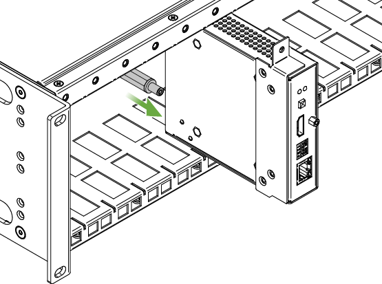
Step 2.5V DC power cable connection.
Pull out the 5V DC power cable (highlighted with grey) belonging to the desired slot from the enclosure, and connect it to the power connector of the extender.
Step 3.Fastening the extender in the mounting slot.
Place the extender (highlighted with grey) to the desired mounting slot, and fasten the extender bracket with 1 pc M4x8mm PH, D head unpainted screw with a PH1 screwdriver. Pay attention to the guide rails of the cage when placing the extender.

|
Required screw: |

|
|
M4x8, PH, D head, unpainted |
Step 4.Assembly of the Rack Ears and the Cable Guides.
The structure of the rack ears and the cable guides allow three kinds of installations in the Powered Rackmount Cage. The rack ears (highlighted with blue) are assembled to the front side in the foremost position. Two cable guides (highlighted with green) are assembled to the device, one is to the front side in the middle position, the second one is to the rear side in the lower position.
INFO:The example below is recommended if you have a deep rack, and you need cabling on the front and the rear side as well.

Other Compatible Devices
The rackmount cage is compatible with other Lightware extenders, too:
▪HDMI-OPT-TX100
▪HDMI-OPT-TX100R
▪HDMI-OPT-TX200R
▪HDMI-OPT-RX100
▪HDMI-OPT-RX100R
▪HDMI-OPT-RX200R
▪HDMI-3D-OPT-RX150RA
3.3. Mounting the Wall Plate Model
Switch / Outlet Box Compatibility Table
Compatible Lightware Devices:
|
Model |
Color of the front panel |
|
WP-VINX-110P-HDMI-ENC White |
White |
|
WP-VINX-110P-HDMI-ENC Black |
Black |
|
Type |
Part number |
Picture |
|
Carlon B225R-UPC |
7TAA040070R0000 |

|
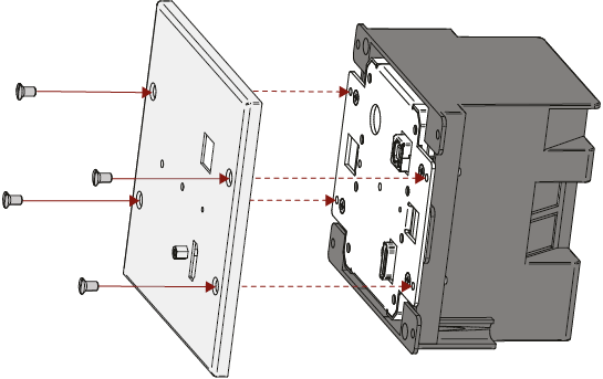
Mounting Steps
The encoder can be easily mounted into an industrial standard switch/outlet box (B225R):
INFO:The switch/outlet box is not supplied with the mounting kit but it can be purchased separately. Please contact sales@lightware.com for the details.

Step 1. Insert the extender into the B225R outlet box and position it to get the holes aligned.
Step 2. Fasten the front side of the extender to the B225R outlet box by fitting the four flat-headed screws.
Step 3. Place the cover on the front side of the extender and position it to get the holes aligned.
Step 4. Fasten the cover to the front side of the extender by fitting the four round-headed screws.
3.4. Mounting the Floor Plate Models
3.4.1. Mounting the FP-VINX-110P-HDMI-ENC-MKM model


3.4.2. Mounting the FP-VINX-110P-HDMI-ENC-MKS model

3.4.3. Mounting the FP-VINX-110P-HDMI-ENC-GES4, -GES9 models

3.5. Electrical Connections
1 GbE LAN and Dante® Audio Out
_numbered.png)
The devices provide standard RJ45 connectors for outgoing/incoming Video/Control signals. Always use high quality Ethernet cable for connecting Encoders and Decoders.
INFO:The connector type and the applied cable is the same for the Dante® audio output.
The Wiring of the Twisted Pair Cables
The recommended termination is based on TIA/EIA T 568 A or TIA/EIA T 568 B standards:

HDMI Input and Output Ports
The devices are assembled with standard 19-pole HDMI connectors for inputs and outputs. Special HDMI cables can be fastened to the housing by the nut.
USB Ports
The USB ports allow USB extension. The Encoders are assembled with USB B or mini-B type port (connecting a computer), and the Decoder devices contain two USB 1.1 and two USB 2.0 compatible A-type port. For more information about the USB extension see the USB Interface section.
Dante® is a registered trademark of Audinate Pty Ltd.
SFP Slots

The module inserted in the SFP slot can be used for network connection (AV transmission). Please note that SFP module is not supplied with the product.
DEFINITION:The small form-factor pluggable (SFP) is a compact, hot swappable optical module transceiver used for both telecommunication and data communication applications. It is a popular industry format jointly developed and supported by many network component vendors. The SFP interface supports data rates up to 1 Gbit/s. *
ATTENTION!Please note that only one of the network ports is available at the same time in a device: either the SFP or the RJ45. When SFP is connected to a network, the RJ45 port is disabled.
* Source: https://en.wikipedia.org/wiki/Small_form-factor_pluggable_transceiver
Maximum Allowed Optical Cable Length
The maximum allowed optical cable length depends on the installed SFP modules. Always check the specification of the optical modules before the fiber optical cabling.
Analog Audio Ports
DIFFERENCE:The connectors mentioned below can be found only on the AP-series' devices.
Input and Output Ports
The connectors are used for receiving/sending unbalanced analog audio signal. They are also known as (3.5 mm or approx. 1/8”) audio jack, phone jack, phone plug and mini-jack plug.

Jack audio plug pin assignments
ATTENTION!The input is noise-sensitive. Applying an unearthed audio source or using a Dual Transformer/Isolator (DTI) device is highly recommended.
ATTENTION!Do not connect a headphone to the Audio output port.
Microphone Input Port (Return Audio)
Mono input port for microphones, including +20 dB gain in the signal path (compared to the forward audio signal level). If this input is connected to a powered equipment, hum noise issue may occur. In this case an isolation transformer (a passive DI box) can help.
ATTENTION!The microphone input port applies a fixed bias to feed the connected electret (condenser) microphone. Thus, it is not suitable for dynamic microphones that do not contain isolation or an impedance matching transformer. (Danger of damage to the microphone.)

Microphone audio plug pin assignments
RS-232 Port
The Basic VINX-series
The quarter rack-sized devices contain a standard RJ12 connector, which is used for RS-232 serial connection. The port can be used to connect serial devices via the supplied serial cables.
The AP-series
The half rack-sized devices contain a standard D-sub9 connector for RS-232 serial connection. The pinout of the connectors are different as follows:

VINX-120AP-HDMI ENC and VINX-210AP-HDMI-ENC (DCE units)

VINX-110AP-HDMI-DEC (DTE unit)
Please see the RS-232 Interface section for more details about the practical usage, and the RS-232 Signal Management (VINX AP-Series) section for details about the signal transmission.
3.6. Connecting Steps

ATTENTION!Please make sure that the VINX devices within a system run the same firmware (package version). If the firmwares are different, the seamless working is not guaranteed.
3.6.1. Preparing the Network
For the correct installation, build a Local Area Network with a Layer 3 (L3) type switch (highly recommended). However, Unicast mode requires only a Layer 2 (L2) switch. In both cases, the switch must support the Multicast routing.
ATTENTION!VINX Encoder and Decoder send certain system commands over multicast packages. If the multicast routing is disabled on the network, the signal transmission may fail.
Layer 2 vs. Layer 3 Switch
The VINX Encoders and Decoders use multicast routing. The managed switch in the network shall offer the following capabilities:
▪IGMPv2
▪IGMP snooping
▪IGMP fast leave
▪IGMP Querier
▪Multicast filtering
▪9k MTU - Jumbo/Giant frames
These features are supported by the Layer 3 type switches. Please see more technical information about the network requirements in the Application Note (LW-AN-001) section.
3.6.2. Point-to-Multipoint Transmission (Multicast Mode)
|
|
Connect an HDMI source device (e.g. a computer) to the HDMI input port of the Encoder. Connect HDMI display devices to the HDMI output port of the Decoder devices for the Video Wall application. |
|
|
Connect the desired VGA source (e.g.a laptop) to the Encoder. |
|
|
Optionally for RS-232 serial transmission: connect the desired devices (e.g. a touch Control, relay box) to the RS-232 ports by the supplied serial cables. |
|
|
Optionally for USB extension: connect USB devices to the USB ports of the Decoders. Connect the desired host device (e.g. computer) to the Encoder via the USB mini-B type port. |
|
|
Optionally for audio transmission: connect the desired audio source device (e.g. a media player) to the audio input port of the Encoder. Optionally for audio extraction: connect an audio amplifier and speakers to the audio output port of the Decoder. |
|
|
Connect CATx cables between the VINX devices and the L3 Switch. Applied cable shall be max. 100 m (CAT5 or CAT7). |
|
|
For devices with local power only: connect the power cord of the supplied adaptor to the DC input first, then to the AC power socket. |
For more information about installation techniques, please see the Installation Checkpoints section.
3.6.3. Point-to-Point Transmission (Unicast Mode)

|
|
Connect an HDMI source device (e.g. a blu-ray player) to the HDMI input port of the Encoder. Connect a HDMI display device to the HDMI output port of the Decoder device. Optionally for audio extraction: connect an audio extractor device between the display device and the Decoder. |
|
|
Connect the desired VGA source (e.g. a computer) to the Encoder. |
|
|
Optionally for USB extension: connect USB devices to the USB ports of the Decoder. Connect the desired host device (e.g. computer) to the Encoder via the USB type-B port. |
|
|
Optionally for audio extraction: connect an audio amplifier and speakers to the audio output port of the audio extractor. Optionally for return audio transmission: connect the desired audio source device (e.g. a microphone) to the audio input port of the Decoder. Connect an audio recorder to the audio input and output ports of the Encoder, thus, you can both record and embed the audio signal in the HDMI stream. |
|
|
Connect CATx cables between the VINX devices and the L3 Switch. Applied cable shall be max. 100 m (CAT5 or CAT7). |
|
|
For devices with local power only: connect the power cord of the supplied adaptor to the DC input first, then to the AC power socket. |
3.6.4. Installation Checkpoints
The following tips increase the successof the installation:
▪Use CAT7 SFTP AWG23 cables for connecting the devices; the maximum allowed cable length is 100m.
▪Supply the devices by local adaptors or by PoE; the feature is enabled on the RJ45 ports by default.
▪Power on the devices as the final step.
▪Connect a computer to the network to arrange the necessary settings easily (see the Software Control Options chapter).
▪Group the devices by the DIP switch or via the built-in website.
▪Make sure that each Encoder has a unique video stream ID. Set the same ID in the desired Decoders and Encoder.
▪Check if the desired input port is selected to transmit.
▪Universal EDID is emulated on the input ports that supports many common resolutions. If necessary, emulate a specific resolution by selecting a factory pre-programmed EDID.
▪Select the desired Decoder for USB transmission in Multicast mode. (The USB connection is established automatically in Unicast mode.) Pay attention to the USB port types: USB 1.1 and USB 2.0 support.
The following chapter describes the features of the device with a few real-life examples.
4.1. VINX Device Concept
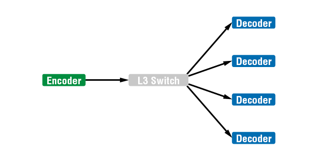
The key feature of the VINX series is the AV signal transmission from an Encoder to many Decoder devices. The video wall can be expanded at a later time, e.g. building a wall with 12 Decoders and add further 12 Decoders later. Another feature is the transmission of RS-232, USB and Infrared signals.
INFO:The USB, Serial, and IR data transmission works independently from the video signal presence.
Unicast Mode (Point-to-Point Connection)
A Decoder is connected to an Encoder device.
Multicast Mode (Point-to-Multi point Connection)
Many Decoder devices are connected to the same Encoder.

* The Analog audio interface contains limitations, please see the details in the Analog Audio Interface section.
The USB transmission is available only at one Encoder-Decoder connection at the same time. The desired device can be activated by the front panel button or via the built-in website.
4.2. Video Interface
The following sections describe the modes of the video transmissions. When the necessary network settings are arranged, the following have to be set:
Video Stream ID Setting
DEFINITION:The Video Stream ID is a four-digit number sequence that identifies a certain stream generated by an Encoder and received by a Decoder.
The Video Stream ID creates the connection between an Encoder and a Decoder. Set the Video stream ID to the same value in the desired VINX devices:
▪Use the DIP switch and set a value other than '0000', or
▪Set the DIP switch to '0000' and define the ID via the built-in web page, see the General Settings section, or
▪Set the DIP switch to '0000' and define the ID by sending the necessary LW3 command to the device, see the Video Wall Settings section.
INFO:The DIP switch state can be ignored by an LW3 command, see the DIP Switch Enable section.
Unicast/Multicast Mode Setting
DEFINITION:The Unicast mode is for point-point connection: assign an Encoder and a Decoder directly to each other. The devices can be connected directly or via the L3 switch.
DEFINITION:The Multicast mode is for point-multipoint connection: assign an Encoder and many Decoders to each other (L3 switch is a must in this mode).
Set the desired working mode of the extenders by:
▪Selecting the mode via the built-in web page, see the Advanced Settings section, or
▪Sending the necessary LW3 command to the device, see the Setting the Working Mode (Unicast/Multicast) section.
Delay in the Video Transmission
Due to the design of the devices, frame delay is in the signal transmission from the Encoder towards the Decoder. For further details, see the Delay in the Video Transmission section.
Supported Signal Formats
See the list of supported signal formats in the Supported Resolutions section.
ATTENTION!Encoder accepts 3840x2160@60Hz 4:2:0 signal but the local HDMI output of the encoder is able to transmit it. This resolution cannot be transmitted to the decoders.
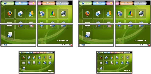
4.2.1. One-to-one Video Transmission (Unicast Mode)
The Encoder and the Decoder devices are arranged in a LAN by connecting them to an L2 or L3 switch. By setting the extenders to Unicast mode, it is possible to extend the video signal via an Encoder to a dedicated Decoder.

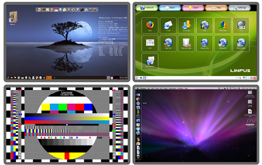
Displayed Images of the Sinks Connected to the Decoders:
INFO:The Encoder and the Decoder can be connected directly and set to Unicast mode. In this case there is no need an L2/L3 switch, but there is no way to communicate with other VINX devices.
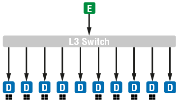
4.2.2. One-to-All Video Transmission (Multicast Mode)
The Encoder and Decoder devices are arranged in a LAN by connecting them to an L3 switch. By setting the extenders to Multicast mode, a certain video can be extended from an Encoder to multiple Decoders.


Video Wall Montage
Tiled Video Wall
Multicast Mode with Video Wall
The Layout


Features
▪2x2-sized video wall is defined and two further single displays are installed (bottom row).
▪Any of the video signals can be displayed on the wall and on a single display device.
▪The other video signal can be seen on the other display device.
▪The video signal on the wall can be changed by using software tools (built-in web or LW3 protocol commands).
Legend

Two Video Walls and Local Monitors with One Encoder
The Layout
Features
▪Two 2x2-sized video walls are defined and two further single displays are installed (e.g. the video walls and the local displays are located in different rooms).
▪One video signal is displayed on the two video walls and on two local monitors.
Small View and Large View Combined in Multicast Mode
The Layout


Features
▪3x4-sized video wall is defined and further four single displays are installed (bottom row).
▪Any of the video signals can be displayed on the wall and on a single display device.
▪The other video signals can be seen on the single display devices (bottom row).
▪The video signal on the wall can be changed by using software tools (built-in web or LW3 protocol commands).
DIFFERENCE:The analog audio option is available only in VINX AP-series.
Unicast Mode
The Layout

Features
▪The audio signal of the Media player is transmitted to the Audio amplifier (forward audio).
▪The microphone signal is routed back to the Audio recorder device (return audio).
ATTENTION!The return audio (from the Decoder to the Encoder) is available only if the analog audio input is selected in the Encoder to transmit towards the Decoder. Thus, the other analog audio signal (MIC IN) connected to the Decoder can be routed back to the Audio output of the Encoder.
ATTENTION!The microphone input port applies a fixed bias to feed the connected electret (condenser) microphone. Thus, it is not suitable for dynamic microphones that do not contain isolation or an impedance matching transformer. (Danger of damage to the microphone.)
Multicast Mode
The Layout

Features
▪The analog audio signal can be selected in the Encoder and would be embedded in the video stream in the Decoder.
INFO:If there is no video input, the encoder shall still transmit the audio from its analog audio input. The destination shall be the decoders that are subscribed to the Video Stream ID set in the encoder.
USB 1.1 and USB 2.0 data transmission operates between an Encoder and a certain Decoder device. Connect the host device (e.g. a computer) to the Encoder and the USB devices to the Decoder. Supported USB devices:
▪USB HID devices: keyboard, mouse, presenter.
▪Mass storage devices: USB flash drive, external hard drive.
ATTENTION!The USB ports are not recommended for time-sensitive applications (e.g. webcam).
The maximum data transmission rate of USB 2.0 ports is 5 MBit/s.
The transmission works in Unicast and Multicast mode as well, but in case of the latter, the desired Decoder has to be selected by any of the following ways:
▪Pressing the Mode button on the front panel for less than three seconds (the connected display device will show Starting USB, the other Sinks will show Stopping USB on the screen),
▪Pressing the Acquire USB connection button in the Advanced tab on the built-in web page (see the USB Settings (Multicast Mode) section), or
▪Sending an LW3 command to the desired Decoder.
The USB devices connected to the other Decoders will be still powered, but the data transmission is suspended.
ATTENTION!USB 1.1 ports can be used for the stream changing, see the Keyboard Shortcuts section.
ATTENTION!The active Decoder works like an extended USB hub connected to a computer. Pay attention to the storage device to remove safely before unplugging it or interrupting during a disc operation.
INFO:The USB transmission is automatically enabled between the Encoder and the Decoder in Unicast mode.

USB Transmission between an Encoder and a Decoder
4.5. Dante® Audio Output Interface
DIFFERENCE:The following section refers to the VINX-120AP-HDMI-ENC-DNT model only.
VINX-120AP-HDMI-ENC-DNT variant contains a special module that allows de-embedding the audio stream of the incoming HDMI signal and transmitting as a 2-channel Dante® or AES67 source over the dedicated RJ45 connector. #dante #audio
ATTENTION!Analog audio input signal cannot be routed to the Dante® audio output.
Port Diagram of VINX-120AP-HDMI-ENC-DNT

* The analog audio transmission (opposite direction than the video stream) is available only in Unicast mode.
Supported Audio
|
Input audio type |
Signal support |
|
2-ch LPCM ** |
supported |
|
Multichannel |
not supported |
|
Compressed DTS/Dolby |
not supported |
** The supported sample rates are 44.1, 48, and 96 kHz.
Dante® is a registered trademark of Audinate Pty Ltd.
Important Notes
▪It is essential to have the right QoS settings in the network switch where the Dante® audio is connected to. See the details in the Application Note (LW-AN-001) section.
▪Even if the Audio network and the video network are separated on distinct LANs (with 2x RJ45 connectors), the Dante® audio can be transmitted over the same network that is used for the VINX video streaming.
▪The AES67 mode is supported by the VINX extender, and can be set in the Dante® Controller software.
▪Multichannel or encoded audio format cannot be de-embedded. In this case, no audio is sent to the Dante® network.
▪Limitation: VINX video stream and Dante® audio stream is not in sync; Dante® audio is 1.1 frame early. The delay occurs during the video transmission from the Encoder towards the Decoder; see more details in Delay in the Video Transmission section.
▪Dante® audio cannot be received by the VINX device.
Settings and Signal Routing

All these features are available in the Dante Controller software, which can be downloaded from the manufacturer's web page:
https://www.audinate.com/products/software
Device Settings
The discovered Dante®-compatible devices are displayed with middle-blue color. Double-click on the name to open the device settings.
The default device name is:
VINX-<Dante_MAC_address_last 6_characters>
It can be changed under Device config tab. Similarly, the channel names can also be changed. NSC-01 is another device with Dante® audio interface.

Press the button to identify the device: the LEDs of the RJ45 connector will blink six times in red.
DIFFERENCE:The WP-VINX-110P-HDMI-ENC model does not have a serial port, thus this feature is unavailable with the wall plate.
Serial data transmission works between an Encoder and all the connected Decoders that have the same Video Stream ID. This transmission is independent from the current working mode (Unicast/Multicast). To connect serial devices, please use the cables supplied with the extenders.
ATTENTION!The serial data is transmitted only if video is transmitted between the affected devices.
Pass-through Mode
DEFINITION:The Pass-through mode means fully transparent bidirectional data transmission from an RS-232 port of a VINX Extender to an RS-232 port of a VINX Decoder – and Vice versa.
All data received from the serial ports of the Decoders is transmitted to the serial port of the Encoder and vice versa: the data received from the serial port of the Encoder is transmitted to the serial ports of all connected Decoders.
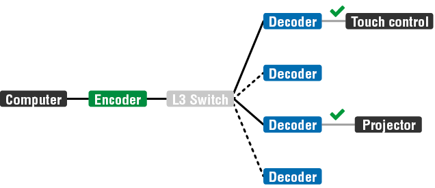
RS-232 Data Transmission (Pass-through mode)
Please note that transmitting data between two Decoders is not possible; see the figure above: sending serial data from the Touch Control to the Projector is not possible.
ATTENTION!The data transmission works only if the serial port parameters are set to the same values in all devices: serial data sender/receiver and the VINX Encoder and Decoder devices.
Command Injection Mode
DEFINITION:The Command Injection mode is like an RS-232–TCP/IP bidirectional converter. The mode allows data transmission between a TCP/IP device and a serial device.
When a device is connected to the network (e.g. TCP/IP connection from a computer) and a serial device is connected to the RS-232 port of a VINX device, they can communicate with each other.

RS-232 Data Transmission (Command Injection mode)
The mode can be enabled as described in the Setting the RS-232 Port Mode section.
4.7. Cleartext Login Feature
DIFFERENCE:This feature is available from firmware v3.1.0.
The Cleartext Login tool allows setting a password for login, thus the device will not accept any command coming from an interface (LW3, Ethernet, etc…), only the device type and the serial number can be queried without login.
By default, Cleartext login is disabled in the devices.
INFO:In case of VINX devces RS-232 interface is not protected by the password, but the Built-in web is.
The Login feature is available in the LDC under the Main Settings menu.
For more information, see the Cleartext Login (Login Settings) section.
The VINX extenders allow setting all the parameters via a user-friendly interface. Open a web browser (Google Chrome or Mozilla Firefox is highly recommended) and connect to the extender to access the parameters and settings. The other option is to use the Lightware Device Controller (LDC) software and connect to the device without a web browser. The features are described in the coming sections.
5.1. Software Control Modes
The VINX device can be controlled by the following ways:

▪Using the built-in web page,
▪Using the Lightware Device Controller (LDC) software, or
▪Sending LW3 commands (detailed in the Programmer's Reference chapter).
Built-in web page vs. LDC
The LDC and the built-in web page shows the same content, but there are some minor differences:
|
Function |
Built-in Web |
LDC |
|
Platform |
Mozilla Firefox, Google Chrome |
Windows, mac OS |
|
Installation |
Web browser needed only |
Required |
|
Firmware update |
|
- |
|
Device discovery |
- |
|
ATTENTION!If you prefer LDC, make sure the software is up-to-date. If a new VINX firmware is released, the LDC will show the changes only if the program is also updated.
The Main window – displayed on a mobile device
INFO:Even though the LDC is introduced briefly, this chapter contains screenshots using the built-in web page.

The Main window – displayed in LDC
5.2. Connecting Using Lightware Device Controller
One option for controlling is to use the well-known LDC software. Download it from www.lightware.com and install. After the installation, the Windows and the macOS applications have the same look and functionality. This type of the installer is equal with the Normal install in case of Windows and results in an updateable version with the same attributes.
Installation for Windows OS
Step 1.Run the installer. If the User Account Control drops a pop-up message, click Yes.
Step 2.During the installation you will be prompted to select the type of the installation: normal and the snapshot install:
|
Normal install |
Snapshot install |
|
Available for Windows and macOS |
Available for Windows |
|
The installer can update only this instance |
Cannot be updated |
|
Only one updateable instance can exist for all users |
Different versions can be installed for all users |
Comparison of the Installation Types
ATTENTION!The minimum display resolution is 1280x720.
ATTENTION!Using the Normal install as the default value is highly recommended.
Installation for macOS
ATTENTION!Please check the firewall settings on the macOS device. LDC needs to be added to the exeptions of the blocked software for proper operation.
Mount the DMG file by double clicking on it and drag the LDC icon over the Applications icon to copy the program into the Applications folder. If you want to copy the LDC into another location, just drag the icon over the desired folder.
5.2.1. Updating the LDC
When the Device Discovery window appears automatically, the program checks the available updates on Lightware’s website and opens the update window if LDC updates are found (default setting).
Set the desired update setting in the Options section. When the Check for updates automatically option is marked, the LDC tries to find a new version after startup.
INFO:The Update window can be opened manually by clicking on the question mark and the Update button.
5.2.2. Running the LDC
Launch the LDC software. The Ethernet tab consists of two lists:

▪You can add any Lightware device that is connected via Ethernet, no need to browse all available devices. Devices can be added in two ways:
▪by pressing the Add button and entering the desired device's IP address or the hostname, if it is supported. The hostname allows setting a unique name to identify the device in the network. If the host name is saved in this window, and the IP address is changing, the device will still be available and connectible, or
▪by marking the desired device with the symbol in the All Devices list.
▪All Devices: All Lightware devices are listed that are available in the connected network.
DIFFERENCE:Hostname setting function is only available with firmware version v3.2.2.
INFO:The host name may contain uppercase (A-Z) and lowercase (a-z) letters of the English alphabet, as well as numbers (0-9) and the hyphen character ( - ).
Select a device and click on the green Connect button, or just double-click on it.

Device Discovery Window
Command Line Parameters

The common way to start the software is to double-click on the LDC icon, but you can use command line parameters for special functions as follows.
Direct Connection to a Known IP Address
The LDC can be connected to a device with a defined IP address directly; in this case, the Device Discovery window is not displayed. Apply the command line parameters as follows (for VINX devices – and for LW3 devices in general – use the port number 6107):
Format: LightwareDeviceController -i <IP_address>:<port>
Example: LightwareDeviceController -i 192.168.0.20:6107
Adjusting the Zoom
The window can be zoomed to a specific value to fit to the resolution of the desktop (higher/lower). '1' is the
default value (100%).
Format: LightwareDeviceController -z <magnifying_value>
Example: LightwareDeviceController -z 1.2
ATTENTION!The last set value is stored and applied when LDC is started without a parameter
Further Tools
The Tools menu contains the following options:
▪Log Viewer: The tool can be used for reviewing log files that have been saved previously.
▪Create EDID: This tool opens the Easy EDID Creator wizard, which can be used for creating unique EDIDs in a few simple steps. Functionality is the same as it is in the Easy EDID Creator.
▪Demo Mode: This is a virtual MX-FR17 matrix router with full functionality built into the LDC. Functions and options are the same as of a real MX-FR17 device.
The Terminal window is also available by pressing its button on the bottom.
5.3. Connecting via the Built-in Web Page
ATTENTION!The supported web browsers are Google Chrome and Mozilla Firefox.
Another option for controlling the VINX device is to open the built-in web page. It is enough to connect to one device, the others can be discovered easily. If you successfully connected to an Encoder, all the other counterpart devices will be listed in the Main settings tab (General section). Vice versa: when connected to a Decoder, the available Encoders are listed in the Main settings tab.
If You do not Know the IP Address
You can do any of the followings:
▪Connect a monitor/projector to a Decoder; the deafult VINX screen will show its IP address.
▪Find the MAC address of the desired device (located on the top of the extender) and launch the web browser:
a)In case of a Decoder, type the following in the address line:
http://LWR-clientAABBCCDDEEFF.local
b)In case of an Encoder, Type the following in the address line:
http://LWR-gatewayAABBCCDDEEFF.local
AABBCCDDEEFF is the MAC address of the device (without hyphens) – which can be seen on the housing of the extender.
The Default IP Address
The default IP Address Setting is DHCP with Auto IP and works as follows:
▪If there is a DHCP server in the network: the VINX device got an IP address from the DHCP server. Make sure the control PC is connected to the same network.
▪If there is no DHCP server in the network: the VINX device generates an IP address in the 169.254.x.x range (AutoIP). Set the IP address of the control PC to match with this range (with subnet mask 255.255.0.0).
After a successful connection you can change the IP settings.
5.4. Main Settings (Encoder)
Unicast Mode #unicast
The Video stream ID is not only used in Multicast mode. To assign an Encoder and a Decoder in Unicast mode, set the same Video stream ID in both devices.
Grouping the VINX Extenders #multicast
Video Stream ID #videostreamid #streamid
The current ID number is shown. The following rules are defined to avoid Video Stream ID conflicts:
▪When the DIP switch is in 0000 position, the SW setting will be valid, or else the HW setting (DIP switch) will be valid.
▪When the DIP switch is set back to 0000, the SW setting will inherit the ID (the previous DIP switch value).
▪SW setting and HW setting can be combined within the group, but in this case the DIP switch value will determine the common Video Stream ID.
INFO:The DIP switch state can be ignored by an LW3 command, see the DIP Switch Enable section.
Decoder Assignment
The list contains the VINX devices that are available within the same subnet. Mark the desired devices to set the same ID.
Device Label #label #devicelabel

A unique name (up to 32 ASCII characters) can be set that will be visible when the given device is listed in the built-in web page of other VINX devices. Furthermore, the name is listed when browsing the client list of a DHCP server.
ATTENTION!It might happen that two or more Encoders are installed in the same system with the same Video Stream ID. This would result in display problems (e.g. more mouse cursors are displayed when desktop images are shown). Check the Video Stream ID settings of the Encoders.
ATTENTION!The Video wall setup submenu is not displayed on mobile devices in most cases due to the limitation of these screens.
TIPS AND TRICKS:Press the VINX drawing in the top left corner to navigate back to the Device Discovery window.
The Main Window of the Built-in Web Page (Encoder) – Displayed on a Computer
Symbol Legend

5.4.2. Cleartext Login (Login Settings)
DIFFERENCE:This feature is available from firmware v3.1.0.
This cleartext login tool allows setting a password for login, thus the device will not accept any command coming from a control interface (LW3, Ethernet, etc…) without login. The device will be visible in the Device Discovery window (as the device type and the serial number can be queried without login) but connection can be established only after successful login. The login is valid until a TCP socket break in case of Ethernet connection. #login
ATTENTION!If the login is enabled, the built-In miniweb will also require the password upon entering.
INFO:The login password is erased and the login protection is disabled when restoring the factory default values.

The password may contain uppercase (A-Z) and lowercase (a-z) letters of the English alphabet, as well as numbers (0-9). The minimum length of a password is four characters.
ATTENTION!Make sure to tick in the Enable login requests option before clicking on the Apply button, otherwise the login function will remain inactive.
This function is also available on Decoders' interface with the same conditions.
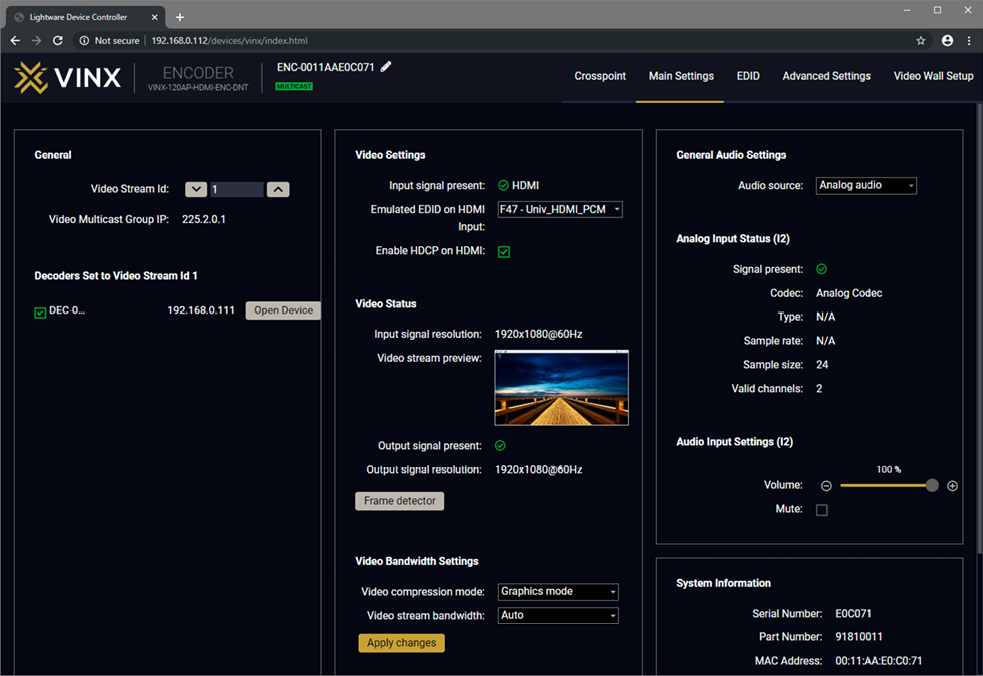
5.4.3. Video Status and Settings
The properties of the incoming and outgoing video signals are displayed in the following sections.
Video Settings #hdcp
▪The emulated EDID can be selected (see the EDID Operations section).
▪Setting the HDCP status on the input:
=Enable: the connected source will detect the Encoder to be HDCP-compliant.
=Disable: the connected source will detect the Encoder to be not HDCP-compliant. Thus, if the content allows it, the signal will not be HDCP encrypted.
Video Status #status
▪Input signal presence and Video stream preview. The image is updated approx. every third seconds.
▪Displaying the Frame Detector in a new window, see the Frame Detector section.
ATTENTION!If the HDCP setting is changed, a window will pop up to confirm, as the device will be restarted to apply the settings.
ATTENTION!The EDID information cannot be read by the source attached to the HDMI input of an Encoder if HDCP is disabled on the input. This may stop the video transmission in case of certain source devices.
Video Source Selection #source
DIFFERENCE:The feature is available in VINX-210AP-HDMI-ENC device only.
▪The desired video source can be selected from the drop-down menu: HDMI / VGA / Auto.
▪Auto mode: the first connected source shall remain active as long as signal is present on the respective input. If sync is lost for at least 3 seconds, a switch over to the other source shall occur. No automatic switch back to the original input shall occur when the signal is restored.
Video Bandwidth Settings
Compression Mode #compression
When the network bandwidth is not enough to transmit the video signal, the following modes are available in the Encoder:
▪Movie mode (Lower image quality @ Less bandwidth): The image quality is adjusted to the available bandwidth. If the bandwidth is decreased, the image quality will be lower, but the video streaming will be continuous.
▪Graphics mode (Best image quality @ High bandwidth): The image quality is kept at a high level. If the bandwidth is decreased, the image quality does not change, but frame drop may appear.
The setting takes effect when the available bandwidth is less than required.
Video Stream Bandwidth #bandwidth
A specific bandwidth limitation can be set in the Encoder that affects only the video signal transmission. The following values are available:
Auto / 10 Mbps / 50 Mbps / 100 Mbps / 150 Mbps / 200 Mbps
The Auto setting is the default value, which means the available bandwidth is determined according to current network traffic.
ATTENTION!If the Bandwidth setting is changed, a window will pop up to confirm, as the device will be restarted to apply the settings.
5.4.4. Audio Settings
The General audio settings allow the selection of the desired audio source and setting the volume of the output signal.
Auto select analog mode: the Analog audio input port is selected when a plug is connected.
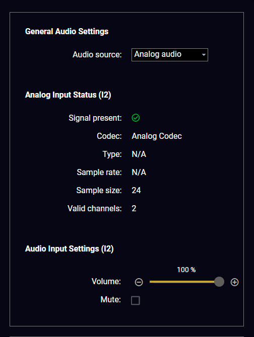
#audio #analogaudio #volume #mute #unmute
5.5.1. General Settings
Unicast Mode #unicast
The Video stream ID is not only used in Multicast mode. To assign an Encoder and a Decoder in Unicast mode, set the same Video stream ID in both devices.
Grouping the VINX Extenders #multicast
Video Stream ID #videostreamid #streamid
The current ID number is shown. The following rules are defined to avoid Video Stream ID conflicts:
▪When the DIP switch is in 0000 position, the SW setting will be valid, or else the HW setting (DIP switch) will be valid.
▪When the DIP switch is set back to 0000, the SW setting will inherit the ID (the previous DIP switch value).
▪SW setting and HW setting can be combined within the group, but in this case the DIP switch value will determine the common Video Stream ID.
INFO:The DIP switch state can be ignored by an LW3 command, see the DIP Switch Enable section.
Encoder-Decoder Assignment
The list contains the VINX encoders available in the same subnet. Mark the desired devices to set the same ID.
Device Label #label #devicelabel
A unique name (up to 32 ASCII characters) can be set that will be visible when the given device is listed in the built-in web page of other VINX devices. Furthermore, the name is listed when browsing the client list of a DHCP server.
ATTENTION!It might happen that two or more Encoders are installed in the same system with the same Video Stream ID. This would result in display problems (e.g. more mouse cursors are displayed when desktop images are shown). Check the Video Stream ID settings of the Encoders.
ATTENTION!The Video wall setup submenu is not displayed on mobile devices in most cases due to the limitation of these screens.
5.5.2. Video Status and Settings
The content of the window is almost the same as in the case of the Encoder. The Video Status Information is filled with details when valid signal is detected and a sink is connected. The addition is the Scaler settings, which is also available on the Advanced Settings page.
DEFINITION:Scaling a video signal means changing the image resolution. The new resolution may change the aspect ratio and/or the appearance of the image. #status

The Main Window of the Built-in Web Page (Decoder) – Displayed on a Computer
No Signal Screen
VINX decoders have a built-in screen that is sent to the output when there is no incoming signal on that particular decoder. It can be changed in this section to show a black screen.

The default VINX "no signal screen"
ATTENTION!Press the Apply button to apply the new setting, which makes the device reboot.
Uploading a Custom Logo
Users can upload custom logo images to be shown on the screen when there is no incoming signal on that particular decoder.
To upload a file, click on the Upload image button, browse the file in the pop-up window, and click open.
The name of the file to be uploaded may contain only letters of the English alphabet (A-z) and numbers (0-9).
The device has 1.5 MB free space for this feature. The current amount of free space available is displayed in this section in red. You can upload any number of files within the limits of the amount of free space available.
Additionally, you can set what to display when there is no connection with the encoder, when there is no incoming video signal from the encoder, or you can override the active video using the drop-down menus.

Video Output Setting
DIFFERENCE:The video output port of the decoder can be disabled from firmware package v3.3.1. In case previous firmware packages the video output is always enabled and cannot be modified. #new
Output Enabled
▪Auto: the HDMI +5V is enabled and AV signal is transmitted on the output port if any signal is transmitted from the encoder.
▪Always off: the HDMI +5V is disabled and the output port does not transmit AV signal.
The outgoing video signal can be set in each Decoder separately. #scaler
Output Scaling
▪Pass-through: the resolution, refresh rate and the type of the outgoing and incoming signals are the same.
▪Auto detect from EDID: the resolution of the outgoing video is scaled to meet with the preferred timing coming from the EDID of the connected display device.
▪Custom: a wide range of the scaling resolutions are available from 640x480 till 4096x2160.
ATTENTION!The scaler has the following limitations:
▪Can’t upscale from sources having a horizontal resolution greater than 1920 pixels. For example, 3840x2160 to 4096x2160 is not supported.
▪Can only do horizontal+vertical half downscale. For example: 4096x2160 to 1920x1080: 128 horizontal pixels will be missing (4096/2 - 1920 = 128).
When scaling down, the Receiver can only go down to a minimum of half of the input resolution. For example, 3840x2160p (4K) can be scaled down to a minimum of 1920x1080p. Scaling 4K to 720p will not display correctly. Scaling up does not have this limitation.
Output Standard
When the Output scaling is set to Custom, the outgoing signal can be set to DVI or HDMI.
Picture Rotation/Flip #rotation #flip
The following options are available:
▪No rotation,
▪Flip vertically
▪Flip horizontally
▪Rotate by 90 / 180 / 270 degrees
The ports can show detailed information about the signal, like blanking intervals and active video resolution. This feature is a good troubleshooter if compatibility problems occur during system installation. Lightware’s Frame Detector function works like a signal analyzer and makes it possible to determine the exact video format that is present on the port, thus helping to identify many problems. E.g. actual timing parameters may differ from the expected and this may cause some displays to drop the picture. #framedetector

Frame Detector (Opened in a New Tab)
Frame Detector measures detailed timings on the video signals just like a built-in oscilloscope, but it is much more easy to use. Actual display area shows the active video size (light grey). Dark grey area of the full frame is the blanking interval, which can contain the info frames and embedded audio data for HDMI signals. Shown values are measured directly on the signal and not retrieved only from the HDMI info frames.
Audio sink: you can select where to transmit the audio, towards the HDMI sink and/or the analog audio device connected to the Decoder.
The volume of the analog audio can be set by using the slider.
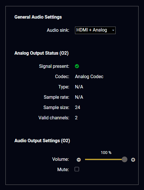
General Audio Settings in a Decoder
#audio #analogaudio #volume #mute #unmute
5.6. Crosspoint Menu
The page allows the user to make crosspoint switches between the encoders and the decoder end-points (individual decoders or video walls) in the system. From firmware package v3.0.1, all connected devices in the network (even if the number of endpoints exceeds 100) will appear on the Crosspoint page. #crosspoint #switch
The TX means the Encoder, the RX means the Decoder, and the defined Video Walls are shown as VW.
ATTENTION!Please note that the Decoders that belong to a Video wall will not be displayed as individual devices.
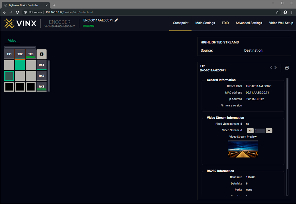
The Crosspoint Menu
The applied icons in the Crosspoint mean different states as follows:
|
|
Unselected connection |
|
Selected but disabled connection |
||
|
|
Selected connection with no signal present |
|
Active stream, but no signal present |
||
|
|
Selected connection with signal present |
|
Stream ID is set by DIP switch |
||
|
|
Unselected and disabled connection |
|
Signal present |


Press the  button to open the Legend window and display the list above.
5.6.1. Grid view
The crosspoint settings can be viewed in two different ways, one of which is the grid view. This is the default screen when a device is opened through LDC or the built-in web. In this screen you can see a crosspoint grid with the Encoder devices in the top row and the Decoder devices in the far right column.
The order is based on the MAC address of the devices.
On the right side you can find the most important settings and information on the chosen device.

5.6.2. Tile view
The crosspoint menu also offers a view that shows the video signal as a preview on all Encoder and Decoder devices. This also serves to see which Decoders are connected to a certain Encoder, as the Decoders do not contain a preview, the screen shown is coming from the connected Encoder. The image of the decoders on this page does not change if a custom logo is set on the device, even if the connected display shows the custom logo. The image of the screens is updated every three seconds, in a way that does not pose a risk to people with photosensitive issues.
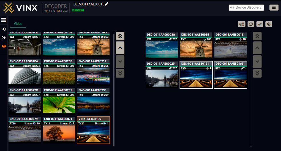
When you select an Encoder in this page, it will be highlighted in orange, and all connected Decoders will be highlighted in white. If you select a Decoder, it will be highlighted in orange, along with the connected Encoder.
On the left side you can find the Display modes. You can open the menu by clicking on the icon, or you can select the mode without opening it. This menu also contains the list of the selected and connected ports, visible only when the menu is open.
You can see several buttons in the top right corner: Parameters, Autotake, Take and Cancel.
Parameters button
When you select a device, the Parameters button becomes active. By clicking on it, you can access the most important information of the chosen device.

Cancel button
By pressing the Cancel button, you can deselect all of the devices that have been selected.

Take and Autotake buttons are explained in the following section.


5.6.2.1. Display Modes

View Mode
The mode allows to display the current crosspoint-state. The crosspoint cannot be changed in this mode, but port settings are available. This mode is active on default.
Input Switch Mode

The mode can also be named as ‘Input priority-mode’: an input port has to be selected first, then the connected output port(s) is/are shown. Thus, the output port(s) connected to the input port can be changed.
Output Switch Mode

This mode can also be named as ‘Output priority-mode': an output port has to be selected first, then connected input port is shown. Thus, the output port connected to the input port can be changed. Output ports can be (un)locked or (un)muted only in Output switch mode. #crosspoint #switch
5.6.2.2. Crosspoint Operations
Switching in Take Mode #autotakemode

The grey Autotake button means Take mode is active. Any crosspoint change – (dis)connecting ports to/from the previously selected port – is executed only after pressing the Take button. The following steps describe the process of the switching:
Step 1.Press the desired Input switch or Output switch button to select switching mode.
Step 2.Select the desired port; it will be highlighted in orange and displayed on the port bar on the left, too.
Step 3.Connected port(s) is/are highlighted in white and displayed on the port bar on the left, too.
Step 4.Create the desired crosspoint settings by (de)selecting the ports; they will start to blink.
Step 5.Press Take button to execute changes or Cancel to ignore the operations.
INFO:Take mode remains active until it is switched off. Selecting another view mode or menu does not change the Take/Autotake mode state.
Switching in Autotake Mode

The yellow colored Autotake button means Autotake mode is active. Any crosspoint change – (dis)connecting ports to/from the previously selected port – is executed immediately after pressing the port button. Following steps describe the process of the switching:
Step 1.Press the desired Input switch or Output switch button to select switching mode.
Step 2.Select the desired port; it will be highlighted in orange and displayed on the port bar on the left, too.
Step 3.Connected ports are highlighted in white and displayed on the port bar on the left, too.
Step 4.Create the desired crosspoint settings by (de)selecting the ports; the changes are executed immediately.
INFO:Autotake mode remains active until it is switched off. Selecting another view mode or menu does not change the Take/Autotake mode state.
5.7. EDID Menu
DEFINITION:The Extended Display Identification Data (EDID) is the passport of the display devices. It contains information about the capabilities of the display, such as supported resolutions and audio formats, refresh rates, the type and the manufacturer of the display device, etc.
Advanced EDID Management is available in the Encoder. Navigate to the EDID menu. There are two panels: the left contains the Source EDIDs, the right panel contains the Destination places where the EDIDs can be emulated or copied. See more information in the EDID Management section. #edid

The EDID Menu (in an Encoder)
5.7.1. The EDID Memory Structure
The EDID memory consists of four parts:
▪Factory EDID list shows the pre-programmed EDIDs (F1-F132).
▪Decoder EDID list shows the EDIDs of the display devices connected to the assigned Decoders. The Decoders store the last display devices’ EDID on the HDMI output, so there is an EDID shown even if there is no display device attached to the output port at that moment.
▪User memory locations (U1 – U5) can be used to save custom EDIDs. Any EDID from any of the User/Factory/Decoder EDID lists can be copied to the user memory.
▪Emulated EDID shows the currently emulated EDID for the HDMI input port of the Encoder. The source column displays the memory location that the current EDID was routed from.
Changing the Emulated EDID
Step 1.Choose the desired EDID list on the source panel and select an EDID.
Step 2.Select the Emulated tab on the Destination panel.
Step 3.Select the desired port on the right panel.
Step 4.Press the Transfer button to change the emulated EDID.
Learning an EDID
The process is the same as when changing the emulated EDID; the only difference is the Destination panel: select the User tab. This way, one or more EDIDs can be copied into the user memory.
Exporting an EDID
The source EDID can be downloaded as a file (*.EDID) to the computer.

Step 1.Select the desired EDID from the Source panel.
Step 2.Press the Export button and save the file to the computer.
Importing an EDID
Previously saved EDID file (*.EDID) can be uploaded to the user memory:

Step 1.Select the User tab on the Source panel and select a memory slot.
Step 2.Press the Import button below the Source panel.
Step 3.Browse the file in the opening window, then press the Open button. The content of the EDID file is imported into the selected User memory.
ATTENTION!The new EDID overwrites the selected memory place.
Deleting EDID(s)
The EDID(s) from the User memory can be deleted as follows:

Step 1.Select the User tab on the Destination panel.

Step 2.Select the desired memory slot(s); one or more can be selected (Select All and Select None buttons can be used).
Step 3.Press the Clear selected button to delete the EDID(s).
5.8.1. Common Settings (Encoder and Decoder)
The submenu contains two tabs: Multicast and Unicast. The currently valid mode is highlighted with yellow. Press the desired button to choose the mode and access the settings. #unicast #multicast
ATTENTION!When the mode is changed, the device must be restarted; you will get a notification.
Network Settings #network #ipaddress #dhcp
The factory default IP address of the extender is set by the DHCP server. The drop-down list and the further parameters allow changing the network settings to the desired value.
ATTENTION!When the desired Network parameters are set, press the Apply changes button; the device will reboot.
Please use the port number 6107 for connecting to the device directly from a third-party application.
Update Firmware #firmwareversion
For the details, please see the Firmware Update section.
Programmers' LW3 Terminal
See the LW3 Terminal section.
RS-232 Settings #rs232 #rs-232 #serial
The RS-232 serial data transmission is fully transparent between the Encoder and the connected Decoder devices. All data received on the serial port of the Decoders is transmitted to the serial port of the Encoder and vice versa: the data received on the serial port of the Encoder is transmitted to the serial port of all connected Decoders.
ATTENTION!The data transmission works only if the serial port parameters were set to the same values in all the devices: serial data sender/receiver and the VINX Encoder and Decoder devices.
See more information in the RS-232 Interface section.
The Encoder displays the name of the currently connected Decoder.
The Decoder displays whether the USB connection is established; press the button to acquire the connection if needed. #usbkvm #kvm
Restart and Factory Default Settings #reboot #reset #restart
Scroll down to these dedicated buttons. #factory

The Advanced Settings Menu of an Encoder in Multicast Mode
5.8.2. Decoder-related Settings
OSD Settings (the On-Screen Display Feature) #osd
Certain system messages can be displayed on the connected screen; the following are defined:
▪Enable OSD: set it to 'ON' state to enable the OSD feature.
▪HDCP messages: 'HDCP failed'
▪USB messages: 'Requesting USB', 'Starting USB', 'Stopping USB'
▪Video quality messages: 'Graphics mode', 'Movie mode'
▪Dither messages: reserved
▪Other messages: reserved
Press the Apply changes button and restart to save the new settings.
A keyboard connected to the USB 1.1 port of a Decoder can be used to change the assigned Encoder to another one. Thus, the input source of a Decoder can be changed quickly and easily.
INFO:The Video Stream ID of the Decoder is changed when a command is executed.
The shortcut can be set:
▪to select a certain stream directly, or
▪to select the next/previous stream in the list.
Setting (Changing) a Shortcut
Step 1.Open the web page of the desired Decoder and navigate to the Advanced Settings page.
Step 2.Connect an USB keyboard to that computer directly, or through the desired Decoder and the Encoder (make sure the Encoder is connected to the computer via USB).
Step 3.Place the cursor in the desired Shortcut box.
Step 4.Press the desired key combination; the new setting will be displayed and stored.
Executing a Command (Calling a Shortcut)
Connect the keyboard to an USB 1.1 port (not the USB 2.0!) of the desired Decoder. Press the key(s) three times quickly (within 750 ms). Please note that in the case of a combination (e.g. Alt + A), it is enough to hold the first key while pressing the second key three times in quick succession.
Stream ID List #videostreamid #streamid
You can set a custom list of streams, this way, the Previous/Next stream shortcuts will select the streams in the desired order.
Scaler Settings #scaler
The same options as in the Scaler settings section.

The Advanced Settings Menu of a Decoder in Multicast Mode
This window is the surface of the Lightware Protocol 3 (LW3) tree with a terminal window. Commands and specific parameters (which are not available on the graphical user interface of the LDC) can be run and set. The introduction of the LW3 protocol and the most important commands can be found in the Programmer's Reference section.
Legend #terminal
|
|
LW3 Protocol Help |
Displaying the most important information about LW3 protocol commands in a new window. |
|
|
Terminal Window |
Commands and responses with time and date stamps are listed in this window. Sent command starts with ‘>’ character, received response starts with ‘<’ character. The content of the window can be emptied by the Clear button. If the Autoscroll option is ticked, the list is scrolled automatically when a new line is added. |
|
|
Edit Mode |
The default appearance is the read-only mode. If you want to modify the values or parameters, tick the option. You will be prompted to confirm your selection. |
|
|
Protocol Tree |
LW3 protocol tree; select an item to see its content. |
|
|
Node List |
The parameters and nodes of the selected item in the protocol tree are shown. •Manual button: displaying the manual (short description) of the node in a pop-up window. •Set button: Saving the value/parameter typed in the textbox. •Call button: Executing the method, e.g. reloading the factory default settings. |
|
|
Warning Mode |
If this option is enabled, a warning window pops up when you enable the Edit mode. |
|
|
Command Line |
Type the desired command and execute it by pressing the Send button. |
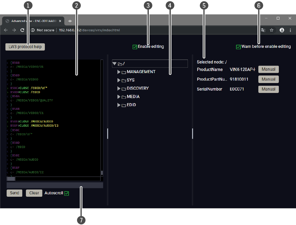
The Terminal Window
5.9. Video Wall Setup
ATTENTION!This tab is displayed only when the device is in Multicast mode. Although changing parameters usually takes effect within an acceptable period of time, it might happen that feedback is not received and not visible on the web page for several seconds.
Basic Rules #videowall
▪One Decoder can be a part of only one video wall.
▪The video wall must have a unique name within a system; the length of the name shall not exceed 24 characters.
▪The video wall parameters are stored in the LW3 protocol tree of the Decoders but you can also create/access it in the Encoder.
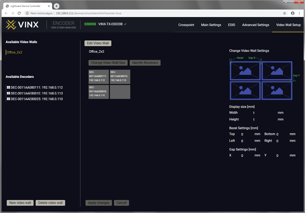
The Video Wall Setup Page
5.9.1. Creating a Video Wall

Step 1.Navigate to the Video Wall Setup page.
Step 2.Press the New video wall button. Enter the desired name of the wall (press the pencil icon to change) and press the Enter or click on the pencil icon.
Step 3.Press the Change Video Wall Size button to set the exact size of the wall. A new window will pop up, click on the desired size (see besides).
Step 4.Drag and drop the Decoders to the desired place in the wall.
Step 5.Press the Apply changes button to save the settings.
ATTENTION!A New video wall is stored only when at least one Decoder is linked to the wall.
5.9.2. Identify the Decoders

The Decoders of a video wall can be identified by pressing the Identify Receivers button. In this case, the IP address and the position in the Video wall is displayed on the connected screens.

5.9.3. Gap and Bezel Settings
ATTENTION!Always press the Apply changes button if you want to save the changes of the parameters mentioned below.
DEFINITION:Hereby defined Gap means the physical distance between the edges of the display devices – see the attached figure.
DEFINITION:The Bezel means the thickness of the Display device's frame – see the attached figure.
In certain cases, the dimensions of the sinks and the arrangement of the video wall requires special parameters to be set. The Gap and Bezel parameters allow the setting of the non-visible areas (between the display devices) of the image:


No Gap (left) and Manually Set Gap (right)
▪No Gap: The left figure shows that no gap is defined. In this case, the whole image is shown on the screens but the image looks a bit distorted.
▪Defined Gap: The right figure shows that gap is defined, therefore some part of the image is not visible, but the appearance of the overall image is more realistic.
Set the bezel and gap parameters that best suit the current image content.
The following parameters can be set:
▪Display Size (width and height): the physical size (dimensions) of the screen (screen size + bezel).
▪Bezel Settings (top, bottom, left, right): the physical size (thickness) of the bezel.
▪Gap Settings (horizontal, vertical): the distance of the displays (see the following section).
INFO:If the Bezel and Gap values are set to zero, the Display size values (dimensions) do not matter.

5.9.4. Modifying a Video Wall
The Name of the Video Wall
Step 1.Press the Edit Video Wall button.
Step 2.Change the name of the video wall and press the Apply changes button.
Changing the Layout of the Decoders
Step 1.Press the Edit Video Wall button.
Step 1.Drag and drop a Decoder to the below indicated red colored (hidden) place; the device will be removed from the wall.
Step 2.Another Decoder can be dragged and dropped to the empty place.
Step 3.Press the Apply changes button to save the settings.
ATTENTION!If you reduce the size of an existing video wall, the Decoders that would be outside of the new area show the original picture.

Changing the Gap and Bezel Settings
Step 1.Press the Edit Video Wall button.
Step 2.Set the desired gap and bezel values and press the Apply changes button the save the settings.
5.9.5. Deleting a Video Wall
Step 1.Select the video wall from the list.
Step 2.Click on the Delete video wall button and confirm in the pop-up window. The original image will be displayed on all connected Decoders.
The device can be controlled through Lightware 3 (LW3) protocol commands to ensure the compatibility with other Lightware products. The supported LW3 commands are described in this chapter.
6.1. Overview
The Lightware Protocol #3 (LW3) is implemented in almost all new Lightware devices (matrix switchers, signal extenders and distribution amplifiers) since 2012. The protocol is ASCII-based and all commands are terminated with a carriage return (Cr, ‘\r’) and line feed (Lf, ‘\n’) pair. It is organized as a tree structure that provides outstanding flexibility and user-friendly handling with ‘nodes’, ‘properties’ and ‘methods’. The Advanced View of the Lightware Device Controller software is the perfect tool for browsing and learning how the LW3 protocol can be used in practice.
6.2. Instructions for the Terminal Application Usage

Terminal Application
The LW3 protocol commands can be applied to the receiver using a terminal application. You need to install one of them to your control device, for example Putty or CLI. #terminal
Establishing Connection
Follow the steps for establishing connection to the receiver:
Step 1.Connect the receiver to a LAN over Ethernet.
Step 2.Open the terminal application (e.g. Putty).
Step 3.Add the IP address of the device (default: 192.168.0.100) and the port number (6107).
Step 4.Select the Raw connection type, and open the connection.
Once the terminal window is opened, you can enter the LW3 protocol commands that are listed in the following sections.

LW3 protocol command communication in a terminal window
6.3. Protocol Rules
6.3.1. The LW3 Tree and Command Structures
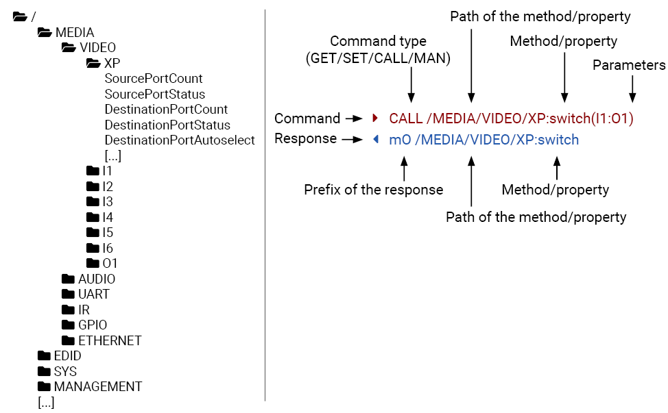
6.3.2. Legend for the Control Commands
Command and Response – Example
»GET•/SYS/MB/GPIO.DipSwitch
«pr•/SYS/MB/GPIO.DipSwitch=<DIP_value>
|
Format |
Description |
|
<in> |
Input port number |
|
<out> |
Output port number |
|
<port> |
Input or output port number |
|
<loc> |
Location number |
|
|
Sent command |
|
|
Received response |
|
• |
Space character |
Further not listed <parameters> are defined at each commands.
6.3.3. General Rules
▪All names and parameters are case-sensitive.
▪The nodes are separated by a slash (‘/’) character.
▪The command lines have to be closed by Carriage return and Line Feed (CrLf)
▪The node name can contain the elements of the English alphabet and numbers.
▪The length of a line (command/response, command type / prefix, path, method/property and parameters together) can be max. 800 bytes.
▪Use the TCP port no. 6107 when using LW3 protocol over Ethernet.
▪When a command is issued by the device, the received response cannot be processed by the CPU.
▪The path of a node has to contain all parent nodes from the root node.
6.3.4. Command Types
GET command
The GET command can be used to get the child nodes, properties and methods of a specific node. It can also be used to get the value of a property. Use the dot character (.) when addressing a property:
»GET /.SerialNumber
«pr /.SerialNumber=87654321
GETALL command
The GETALL command can be used to get all child nodes, properties and methods of a node with one command.
»GETALL /MEDIA/UART
«n- /MEDIA/VIDEO/I1
«n- /MEDIA/VIDEO/O1
«n- /MEDIA/VIDEO/QUALITY
«pr /MEDIA/VIDEO.I1=I1
«pr /MEDIA/VIDEO.O1=O1
«pr /MEDIA/VIDEO.PortCount=2
SET command
The SET command can be used to modify the value of a property. Use the dot character (.) when addressing the property:
»SET /MEDIA/VIDEO/QUALITY.QualityMode=0
«pw /MEDIA/VIDEO/QUALITY.QualityMode=0
CALL command
A method can be invoked by the CALL command. Use the colon character (:) when addressing the method:
»CALL /MEDIA/VIDEO/QUALITY:applySettings(true)
«mO /MEDIA/VIDEO/QUALITY:applySettings
6.3.5. Prefix Summary
DEFINITION:The prefix is a 2-character long code that describes the type of the response.
The following prefixes are defined in the LW3 protocol:
|
Prefix |
Description |
|
n- |
a node |
|
nE |
an error for a node |
|
nm |
a manual of a node |
|
ns |
a child node of a node |
|
pr |
a read-only property |
|
pw |
read-write property |
|
pE |
an error for the property |
|
pm |
a manual for the property |
|
m- |
a method |
|
mO |
a response after a success method execution |
|
mF |
a response after a failed method execution |
|
mE |
an error for a method |
|
mm |
a manual for a method |
6.3.6. Error Messages
There are several error messages defined in the LW3 protocol, all of them have a unique error number.
»SET /MEDIA/UART/P1.Baudrate=9
«pE /MEDIA/UART/P1.Baudrate %E004:Invalid value
6.3.7. Escaping
DEFINITION:An escape sequence is a sequence of characters that does not represent itself when used inside a character or string literal, but is translated into another character or a sequence of characters.
Property values and method parameters can contain characters that are used as control characters in the protocol. They must be escaped. The escape character is the backslash (‘\’) and escaping means injecting a backslash before the character that should be escaped (like in C language).
Control characters are the following: \ { } # % ( ) \r \n \t
The original message:
CALL /MEDIA/UART/P1:sendMessage(Set(01))
The escaped message:
CALL /MEDIA/UART/P1:sendMessage(Set\(01\))
6.3.8. Signature
DEFINITION:The signature is a four-digit-long hexadecimal value that can be optionally placed before every command to keep a command and the corresponding responses together as a group.
Each line is terminated with a carriage return (Cr, ‘\r’) and line feed (Lf, ‘\n’) characters. In several cases, the number of the lines in the response cannot be determined in advance, e.g. the client is intended waiting for the whole response and also wants to be sure that the received lines belong together and to the same command. In these cases, a special feature, the ‘signature’ can be used. In these cases, the response to that particular command will also be preceded by the signature, and the corresponding lines will be between brackets:
»1700#GET /EDID.*
«{1700
«pr /EDID.EdidStatus=F89:E1;D1:E2;D1:E3;D1:E4;F89:E5
«m- /EDID:copy
«m- /EDID:delete
«m- /EDID:reset
«m- /EDID:switch
«m- /EDID:switchAll
«}
INFO:The lines of the signature are also Cr and Lf terminated.
6.3.9. Subscription
DEFINITION:Subscribing to a node means that the user will get a notification if any of the properties of the node is changed.
A user can subscribe to any node. These notifications are asynchronous messages and they are useful to keep the client application up to date, without receiving any unwanted information. When the user does not want to be informed about the changes anymore, he can simply unsubscribe from the node.
ATTENTION!The subscriptions are handled separately for connections. Hence, if the connection is terminated, all registered subscriptions are deleted. After closing a connection, the subscribe command has to be sent in order to get the notifications of the changes on that connection.
Subscribe to a Node
»OPEN /MEDIA/VIDEO
«o- /MEDIA/VIDEO
Get the Active Subscriptions
»OPEN
«o- /MEDIA/VIDEO
«o- /EDID
«o- /DISCOVERY
Subscribe to Multiple Nodes
»OPEN /MEDIA/VIDEO/*
«o- /MEDIA/VIDEO/*
Unsubscribe from a Node
»CLOSE /MEDIA/VIDEO
«c- /MEDIA/VIDEO
Unsubscribe from Multiple Nodes
»CLOSE /MEDIA/VIDEO/*
«c- /MEDIA/VIDEO/*
6.3.10. Notifications about the Changes of the Properties
When the value of a property is changed and the user is subscribed to the node which the property belongs to, an asynchronous notification is generated. This notification is called the ‘change message’. The format of such a message is very similar to the response for the GET command:
«CHG /EDID.EdidStatus=F48:E1
A Short Example of How to Use the Subscription
There are two independent users controlling the device through two independent connections (Connection #1 and Connection #2). The events in the rows occur after each other.
|
»OPEN /MEDIA/VIDEO/QUALITY «o- /MEDIA/VIDEO/QUALITY »GET /MEDIA/VIDEO/Quality.QualityMode «pm /MEDIA/VIDEO/Quality.QualityMode=graphic |
connection #1 |
|
»GET /MEDIA/VIDEO/Quality.QualityMode «pm /MEDIA/VIDEO/QUALITY.QualityMode=graphic «SET /MEDIA/VIDEO/Quality.QualityMode=movie «pw /MEDIA/VIDEO/QUALITY.QualityMode=movie |
connection #2 |
|
«CHG /MEDIA/VIDEO/QUALITY.QualityMode=movie |
connection #1 |
Explanation: The first user (Connection #1) set a subscription to a node. Later the other user (Connection #2) made a change, and thanks to the subscription, the first user got a notification about the change.
6.4. System Commands
6.4.1. Querying the Product Name
Command and Response
»GET•/.ProductName
«pr•/.ProductName=<Product_name>
Parameters
The <Product_name> is the type of the device: it is a read-only parameter and cannot be modified.
Example
»GET /.ProductName
«pr /.ProductName=VINX-120-HDMI-ENC
6.4.2. Setting the Device Label
A unique name can be set that will be visible when the given device is listed in the built-in web page of other VINX devices. Furthermore, the name is listed when browsing the client list of a DHCP server.
ATTENTION!This property is a writable parameter and not the same as the ProductName.
Command and Response #label #devicelabel
»SET•/SYS/MB.DeviceLabel=<Custom_name>
«pw•/SYS/MB.DeviceLabel=<Custom_name>
Parameters
The <Custom_name> may consist of ASCII characters and can be 32 characters long. Longer names are truncated.
Example
»SET /SYS/MB.DeviceLabel=Enc_80
«pw /SYS/MB.DeviceLabel=Enc_80
6.4.3. Querying the Serial Number
Command and Response
»GET•/.SerialNumber
«pr•/.SerialNumber=<serial_nr>
Example
»GET /.SerialNumber
«pr /.SerialNumber=87654321
6.4.4. Querying the Package Version
Command and Response #firmwareversion
»GET•/SYS/MB.PackageVersion
«pr•/SYS/MB.PackageVersion=<package_version>
Example
»GET /SYS/MB.PackageVersion
«pr /SYS/MB.PackageVersion=v1.4.0b7 r90
The extender can be restarted; the current connections (RS-232, USB, etc...) will be terminated.
Command and Response #reboot #restart #reset
»CALL•/SYS:reset()
«mO•/SYS:Reset
Example
»CALL /SYS:reset()
«mO /SYS:reset
6.4.6. Restoring the Factory Default Settings
Command and Response #factory
»CALL•/SYS:factoryDefaults()
«mO•/SYS:factoryDefaults=
Example
»CALL /SYS:factoryDefaults()
«mO /SYS:factoryDefaults=
The device is restarted, the current connections are terminated, the default settings are restored. See the complete list in the Factory Default Settings section.
6.5. Cleartext Login Protection
DIFFERENCE:This feature is available from firmware v3.1.0.
This cleartext login tool allows setting a password for login, thus the device will not accept any command coming from a control interface (LW3, Ethernet, etc…) without login. The device will be visible in the Device Discovery window (as the device type and the serial number can be queried without login) but connection can be established only after successful login. The login is valid until a TCP socket break in case of Ethernet connection. #login
ATTENTION!If the login is enabled, the built-in miniweb will also require the password upon entering.
INFO:The login password is erased and the login is disabled when restoring the factory default values.
The following can be queried without login:
▪ProductName
▪PartNumber
▪SerialNumber
▪FirmwareVersion
▪PackageVersion
▪MacAddress
6.5.1. Setting the Login Password
Command and Response
»CALL·/LOGIN:setPassword(<password>)
«mO·/LOGIN:setPassword
Example
»CALL /LOGIN:setPassword(pr0t3ctED)
«mO /LOGIN:setPassword
The password may contain uppercase (A-Z) and lowercase (a-z) letters of the English alphabet, as well as numbers (0-9). The minimum length of a password is four characters.
6.5.2. Logging into the Device
Command and Response
»CALL·/LOGIN:login(<password>)
«mO·/LOGIN:login
Example
»CALL /LOGIN:login(pr0t3ctED)
«mO /LOGIN:login
After a successful login, the LoggedIn property becomes true and the LW3 tree is available.
6.5.3. Logging out of the Device
Command and Response
»CALL·/LOGIN:logout(<password>)
«mO·/LOGIN:logout
Example
»CALL /LOGIN:logout(pr0t3ctED)
«mO /LOGIN:logout
After a successful logout, the LoggedIn property becomes false and the LW3 tree is protected. Please note the logging out is only possible if the Cleartext login function is enabled.
6.5.4. Enabling/Disabling the Cleartext Login Function
ATTENTION!This property can be changed only, if the LoggedIn property is true.
Command and Response
»SET·/LOGIN:LoginEnable=<login_state>
«pw·/LOGIN.LoginEnable=<login_state>
Parameters
If the <login_state> parameter is true (or 1), the Cleartext login function is enabled, if the parameter is false (or 0), the function is disabled. Please note that the function can be enabled without setting a password by the setPassword method.
Example
»SET /LOGIN.LoginEnable=true
«pw /LOGIN.LoginEnable=true
6.6. Network Configuration
ATTENTION!When you change a network property, the new value is stored, but the applySettings method must be called always to apply the new settings. When two or more serial parameters are changed, the applySettings method is enough to be called once as a final step; it results in the rebooting of the extender.
6.6.1. Querying the IP Address
Command and Response #network #ipsettings #dhcp
»GET•/MANAGEMENT/NETWORK.IpAddress
«pr•/MANAGEMENT/NETWORK.IpAddress=<IP_Address>
Example
»GET /MANAGEMENT/NETWORK.IpAddress
«pr /MANAGEMENT/NETWORK.IpAddress=192.168.0.100
6.6.2. Querying the IP Setup Mode (FW 2.x.x)
DIFFERENCE:The following command is valid with firmware package 2.0.0 or newer.
»GET•/MANAGEMENT/NETWORK.IpSetupMode
«pw•/MANAGEMENT/NETWORK.IpSetupMode=<IP_mode>
Parameters
|
Identifier |
Parameter description |
Parameter values |
|
<IP_mode> |
The currently applied IP setup mode. |
static: using a static IP address, gateway and subnet mask entered by the user. autoip: generating an IP address from the AutoIP range (169.254.x.x), even if a DHCP server is available. dhcponeshot: trying to get the IP address, gateway and subnet mask from a DHCP server. If no answer arrives, fallback to autoIP. dhcpwautoip: (factory default setting) similar to dhcponeshot, but keep on with DHCP discovery queries even after AutoIP fallback. If there is a DHCP response, the IP parameters are set accordingly. dhcpwoautoip: try to get the IP address, gateway and subnet mask from a DHCP server without ever falling back to AutoIP mode. |
Example
»GET /MANAGEMENT/NETWORK.IpSetupMode
«pw /MANAGEMENT/NETWORK.IpSetupMode=static
Explanation
Static IP address (fix IP) setting is valid.
6.6.3. Setting the IP Setup Mode (FW 2.x.x)
DIFFERENCE:The following command is valid with firmware package 2.x.x.
Command and Response
»SET•/MANAGEMENT/NETWORK.IpSetupMode
«pw•/MANAGEMENT/NETWORK.IpSetupMode=<IP_mode>
Parameters
See the previous section.
Example
»SET /MANAGEMENT/NETWORK.IpSetupMode=autoip
«pw /MANAGEMENT/NETWORK.DhcpEnabled=autoip
»CALL /MANAGEMENT/NETWORK:applySettings(1)
«mO /MANAGEMENT/NETWORK:applySettings
INFO:The applySettings method will save and apply the new value, and results in the rebooting of the extender.
Explanation
The IP address is set in the 169.254.x.x range by the extender based on Auto IP (Automatic Private IP Addressing) method.
6.6.4. Querying the DHCP State (FW 1.x.x)
DIFFERENCE:The following command is valid with firmware package 1.x.x.
Command and Response
»GET•/MANAGEMENT/NETWORK.DhcpEnabled
«pw•/MANAGEMENT/NETWORK.DhcpEnabled=<DHCP_state>
Parameters
If the <DHCP_state> parameter is 0 (or false), the device is set to apply a static IP address. If the value is 1 (or true), the device is set to get a dynamic IP address from the DHCP server in the network.
Example
»GET /MANAGEMENT/NETWORK.DhcpEnabled
«pw /MANAGEMENT/NETWORK.DhcpEnabled=true
Explanation
The IP address assignment is dynamic, the device gets the IP address from the DHCP server.
6.6.5. Setting the DHCP State (FW 1.x.x)
DIFFERENCE:The following command is valid with firmware package 1.x.x.
Command and Response
»SET•/MANAGEMENT/NETWORK.DhcpEnabled=<DHCP_state>
«pw•/MANAGEMENT/NETWORK.DhcpEnabled=<DHCP_state>
Parameters
See the previous section.
Example
»SET /MANAGEMENT/NETWORK.DhcpEnabled=0
«pw /MANAGEMENT/NETWORK.DhcpEnabled=false
»CALL /MANAGEMENT/NETWORK:applySettings(1)
«mO /MANAGEMENT/NETWORK:applySettings
INFO:The applySettings method will save and apply the new value, and results in the rebooting of the extender.
Explanation
The IP address assignment is set to static, thus you have to set it manually.
6.6.6. Setting a Static IP Address
DIFFERENCE:Make sure the IP address setting is static:
In case of FW 1.x.x: when the DhcpEnabled property is false, you can set a static IP address.
In case of FW 2.x.x: when the IpSetupMode property is static, you can set a static IP address.
Command and Response
»SET•/MANAGEMENT/NETWORK.StaticIpAddress=<IP_address>
«pw•/MANAGEMENT/NETWORK.StaticIpAddress=<IP_address>
Example
»SET /MANAGEMENT/NETWORK.StaticIpAddress=192.168.0.85
«pw /MANAGEMENT/NETWORK.StaticIpAddress=192.168.0.85
»CALL /MANAGEMENT/NETWORK:applySettings(1)
«mO /MANAGEMENT/NETWORK:applySettings
INFO:The applySettings method will save and apply the new value, and results in the rebooting of the extender.
6.6.7. Querying the Subnet Mask
Command and Response
»GET•/MANAGEMENT/NETWORK.NetworkMask
«pr•/MANAGEMENT/NETWORK.NetworkMask=<subnet_mask>
Example
»GET /MANAGEMENT/NETWORK.NetworkMask
«pr /MANAGEMENT/NETWORK.NetworkMask=255.255.255.0
6.6.8. Setting a Static Subnet Mask
DIFFERENCE:Make sure the IP address setting is static:
In case of FW 1.x.x: when the DhcpEnabled property is false, you can set a static IP address.
In case of FW 2.x.x: when the IpSetupMode property is static, you can set a static IP address.
Command and Response
»SET•/MANAGEMENT/NETWORK.StaticNetworkMask=<subnet_mask>
«pw•/MANAGEMENT/NETWORK.StaticNetworkMask=<subnet_mask>
Example
»SET /MANAGEMENT/NETWORK.StaticNetworkMask=255.255.255.0
«pw /MANAGEMENT/NETWORK.StaticNetworkMask=255.255.255.0
»CALL /MANAGEMENT/NETWORK:applySettings(1)
«mO /MANAGEMENT/NETWORK:applySettings
INFO:The applySettings method will save and apply the new value, and results in the rebooting of the extender.
6.6.9. Querying the Gateway Address
Command and Response
»GET•/MANAGEMENT/NETWORK.GatewayAddress
«pr•/MANAGEMENT/NETWORK.GatewayAddress=<gw_address>
Example
»GET /MANAGEMENT/NETWORK.GatewayAddress
«pr /MANAGEMENT/NETWORK.GatewayAddress=192.168.0.1
6.6.10. Setting a Static Gateway Address
DIFFERENCE:Make sure the IP address setting is static:
In case of FW 1.x.x: when the DhcpEnabled property is false, you can set a static IP address.
In case of FW 2.x.x: when the IpSetupMode property is static, you can set a static IP address.
Command and Response
»SET•/MANAGEMENT/NETWORK.StaticGatewayAddress=<gateway_address>
«pw•/MANAGEMENT/NETWORK.StaticGatewayAddress=<gateway_address>
Example
»SET /MANAGEMENT/NETWORK.StaticGatewayAddress=192.168.0.5
«pw /MANAGEMENT/NETWORK.StaticGatewayAddress=192.168.0.5
»CALL /MANAGEMENT/NETWORK:applySettings(1)
«mO /MANAGEMENT/NETWORK:applySettings
INFO:The applySettings method will save and apply the new value, and results in the rebooting of the extender.
6.6.11. Setting the Host Name
DIFFERENCE:This command is available only with FW package v3.2.2.
The host name is a property that can be used instead of the IP address when connecting to the device. It is also suitable for finding it in the Device Discovery window of the LDC, see more details in the Favorite Devices section. Furthermore, it can be used to open the Built-in Web. If the IP address of the device is changing, the host name can be used as a fix property.
Command and Response
»SET•/MANAGEMENT/NETWORK.HostName=<unique_name>
«pw•/MANAGEMENT/NETWORK.HostName=<unique_name>
Example
»SET /MANAGEMENT/NETWORK.HostName=mydevice
«pw /MANAGEMENT/NETWORK.HostName=mydevice
INFO:The applySettings method will save and apply the new value, and results in the rebooting of the extender.
The host name may contain uppercase (A-Z) and lowercase (a-z) letters of the English alphabet, as well as numbers (0-9) and the hyphen character ( - ).
6.7.1. Querying the Input Video Signal Presence
The input port can be queried if video signal is present.
Command and Response #status
»GET•/MEDIA/VIDEO/<in>.SignalPresent
«pr•/MEDIA/VIDEO/<in>.SignalPresent=<signal_present>
Parameters
If the <signal_present> parameter is 0, then signal is not present at the port. If the value is 1, then signal is present at the input.
Example
»GET /MEDIA/VIDEO/I1.SignalPresent
«pr /MEDIA/VIDEO/I1.SignalPresent=1
6.7.2. Querying the Resolution of the Input Video Signal
The resolution and the refresh rate of the incoming video signal can be queried.
Command and Response #resolution
»GET•/MEDIA/VIDEO/<in>.Resolution
«pr•/MEDIA/VIDEO/<in>.Resolution=<resolution@refresh_rate>
Example
»GET /MEDIA/VIDEO/I1.Resolution
«pr /MEDIA/VIDEO/I1.Resolution=1280x720@60Hz
6.7.3. Querying the Active Input Port
DIFFERENCE:The command below is valid for VINX-210AP-HDMI-ENC device only.
Command and Response
»GET•/MEDIA/VIDEO.InputSource
«pr•/MEDIA/VIDEO.InputSource=<source_ID>
Parameters
|
Identifier |
Parameter description |
Parameter values |
|
<source_ID> |
Identifier of the video input port |
0: unknown 1: HDMI 2: VGA |
Example
»GET /MEDIA/VIDEO.InputSource
«pr /MEDIA/VIDEO.InputSource=1
6.7.4. Querying the Video Input Selection Mode
DIFFERENCE:The command below is valid for VINX-210AP-HDMI-ENC device only.
Command and Response #inputselection
»GET•/MEDIA/VIDEO.SelectionMode
«pw•/MEDIA/VIDEO.SelectionMode=<sel_mode>
Parameters
|
Identifier |
Parameter description |
Parameter values |
|
<sel_mode> |
The currently applied input selection method. |
0: Auto 1: HDMI 2: VGA |
Auto mode: the first connected source shall remain active as long as signal is present on the respective input. If sync is lost for at least 3 seconds, a switch over to the other source shall occur. No automatic switch back to the original input shall occur when the signal is restored.
Example
»GET /MEDIA/VIDEO.SelectionMode
«pw /MEDIA/VIDEO.SelectionMode=0
6.7.5. Setting the Video Input Selection Mode
DIFFERENCE:The command below is valid for VINX-210AP-HDMI-ENC device only.
Command and Response
»SET•/MEDIA/VIDEO.SelectionMode=<sel_mode>
«pw•/MEDIA/VIDEO.SelectionMode=<sel_mode>
Parameters
|
Identifier |
Parameter description |
Parameter values |
|
<sel_mode> |
The currently applied input selection method. |
0: Auto (see the details in previous section) 1: HDMI 2: VGA |
Example
»SET /MEDIA/VIDEO.SelectionMode=1
«pw /MEDIA/VIDEO.SelectionMode=1
6.7.6. Querying the Video Quality Mode
When the network bandwidth is not enough to transmit the video signal, the following modes are available in the Encoder:
▪Movie mode (Lower image quality @ Less bandwidth): The image quality is adjusted to the available bandwidth. If the bandwidth is decreased, the image quality will be lower, but the video streaming is continuous.
▪Graphics mode (Best image quality @ High bandwidth): The image quality is kept at a high level. If the bandwidth is decreased, the image quality does not change, but frame drop may appear.
Command and Response #qualitymode #videoquality
»GET•/MEDIA/VIDEO/QUALITY.QualityMode
«pw•/MEDIA/VIDEO/QUALITY.QualityMode=<quality_mode>
Parameters
The value of the <quality_mode> parameter shows the current mode setting: movie or graphic.
Example
»GET /MEDIA/VIDEO/QUALITY.QualityMode
«pw /MEDIA/VIDEO/QUALITY.QualityMode=movie
6.7.7. Setting the Video Quality Mode
The video quality mode can be set in the Encoder (see the previous section for details about the modes):
Command and Response
»SET•/MEDIA/VIDEO/QUALITY.QualityMode=<quality_mode>
«pw•/MEDIA/VIDEO/QUALITY.QualityMode=<quality_mode>
Parameters
See the previous section.
Example
»SET /MEDIA/VIDEO/QUALITY.QualityMode=graphic
«pw /MEDIA/VIDEO/QUALITY.QualityMode=graphic
6.7.8. Querying the HDCP State
The current state of the HDCP encryption can be queried at the input port; see the HDCP Management section.
»GET•/MEDIA/VIDEO/<in>.HdcpState
«pr•/MEDIA/VIDEO/<in>.HdcpState=<HDCP_state>
Parameters
If the <HDCP_state> parameter is 0, then the HDCP encryption is disabled at the port. If the value is 1, then HDCP encryption is enabled.
Example
»GET /MEDIA/VIDEO/I1.HdcpState
«pr /MEDIA/VIDEO/I1.HdcpState=1
HDCP capability can be enabled/disabled on the input port of the Encoder, thus non-encrypted content can be seen on a non-HDCP compliant display if the content allows it; see the HDCP Management section.
Command and Response
»SET•/MEDIA/VIDEO/<in>.HdcpEnable=<HDCP_state>
«pw•/MEDIA/VIDEO/<in>.HdcpEnable=<HDCP_state>
ATTENTION!When you change this property, the applySettings method must be called always to store the new setting. If the HDCP State is changed, the device is restarted automatically.
Parameters
See the previous section.
Example
»SET /MEDIA/VIDEO/I1.HdcpEnable=0
«pw /MEDIA/VIDEO/I1.HdcpEnable=false
»CALL /MEDIA/VIDEO/I1:applySettings()
«mO /MEDIA/VIDEO/I1:applySettings
ATTENTION!The EDID information cannot be read by the source attached to the HDMI input of an Encoder if HDCP is disabled on the input. That may stop the video transmission in the case of certain source devices.
6.7.10. Force HDCP Version
DIFFERENCE:This command is available from firmware version v3.3.1.
You can set the version of HDCP encryption with this parameter on decoders.
Command and Response
»SET•/MEDIA/VIDEO/<out>.ForceHDCP=<hdcp_version>
«pw•/MEDIA/VIDEO/<out>.ForceHDCP=<hdcp_version>
ATTENTION!When you change this property, the applySettings method must be called always to store the new setting. If the HDCP State is changed, the device is restarted automatically.
Parameters
|
Identifier |
Parameter description |
Parameter values |
|
<hdcp_version> |
The HDCP version to be forced on the output signal. |
1: HDCP 1.4 2: HDCP 2.2 |
Example
»SET /MEDIA/VIDEO/O1.ForceHDCP=2
«pw /MEDIA/VIDEO/O1.ForceHDCP=2
6.8.1. Querying the Resolution of the Output Video Signal
The resolution and the refresh rate of the outgoing video signal can be queried.
Command and Response #resolution
»GET•/MEDIA/VIDEO/<out>.Resolution
«pr•/MEDIA/VIDEO/<out>.Resolution=<resolution@refresh_rate>
Example
»GET /MEDIA/VIDEO/O1.Resolution
«pr /MEDIA/VIDEO/O1.Resolution=1600x1200@60Hz
6.8.2. Querying the Scaling Mode of the Output Video Signal
»GET•/MEDIA/VIDEO/<out>/SCALER.ScalingMode
«pw•/MEDIA/VIDEO/<out>/SCALER.ScalingMode=<sc_mode>
Parameters
|
Identifier |
Parameter description |
Parameter values |
|
<sc_mode> |
Scaling mode |
OFF: Scaling is disabled, the resolution is not changed. EDID: the resolution is set to meet with the preferred timing of the sink device. MANUAL: Scaling is set manually. |
Example
»GET /MEDIA/VIDEO/O1/SCALER.ScalingMode
«pw /MEDIA/VIDEO/O1/SCALER.ScalingMode=MANUAL
See more information about the scaling modes in the Main Settings (Decoder) section.
6.8.3. Setting the Scaling Mode of the Output Video Signal
Command and Response
»SET•/MEDIA/VIDEO/<out>/SCALER.ScalingMode=<sc_mode>
«pw•/MEDIA/VIDEO/<out>/SCALER.ScalingMode=<sc_mode>
Parameters
See the previous section.
Example
»SET /MEDIA/VIDEO/O1/SCALER.ScalingMode=OFF
«pw /MEDIA/VIDEO/O1/SCALER.ScalingMode=OFF
See more information about the scaling modes in the Main Settings (Decoder) section.
6.8.4. Querying the Signal Type of the Output Video Signal
Command and Response #signaltype
»GET•/MEDIA/VIDEO/<out>/SCALER.SignalType
«pw•/MEDIA/VIDEO/<out>/SCALER.SignalType=<sig_type>
Parameters
The <sig_type> can be DVI or HDMI.
Example
»GET /MEDIA/VIDEO/O1/SCALER.SignalType
«pw /MEDIA/VIDEO/O1/SCALER.SignalType=HDMI
6.8.5. Setting the Resolution of the Output Video Signal
The resolution and the refresh rate of the outgoing video signal can be set.
Command and Response
»SET•/MEDIA/VIDEO/<out>/SCALER.OutputResolution
«pw•/MEDIA/VIDEO/<out>/SCALER.OutputResolution=<Resolution_code>
Parameters
The <Resolution_code> is an 8-character long code covering the scaled resolution and refresh rate. The complete list can be found in the Supported Resolutions section.
Example
»SET /MEDIA/VIDEO/O1/SCALER.OutputResolution=81004088
«pw /MEDIA/VIDEO/O1/SCALER.OutputResolution=81004088
Explanation
The new value of the parameter is 81004088, which means the resolution of the output signal is set to 1280x720@60Hz.
ATTENTION!Set the ScalingMode property to MANUAL after changing the Resolution property manually to apply the new settings.
6.8.6. Rotating the screen
The position of the screen on the display can be changed with this command.
Command and Response
»SET•/MEDIA/VIDEO/<out>/VIDEOWALL.Rotation=<value>
«pw•/MEDIA/VIDEO/<out>/VIDEOWALL.Rotation=<value>
Parameters
The <value> can be set to 0 (default, no rotation), 1 (flip vertically), 2 (flip horizontally), 3 (rotate 180 degrees), 5 (rotate 90 degrees) and 6 (rotate 270 degrees). Please note that values 4 and 7 are not supported and break the screen on display.
Example
»SET /MEDIA/VIDEO/O1/VIDEOWALL.Rotation=1
«pw /MEDIA/VIDEO/O1/VIDEOWALL.Rotation=1
INFO:Rotation only applies to the output video signal, it has no effect on the Custom Logo, if one is set.
6.8.7. Setting the No-signal-screen
If there is no video signal, the VINX screen is shown on the output; this can be changed with this command.
Command and Response
»SET•/MEDIA/VIDEO/<out>.EnableVinxGui=<vinx_gui>
«pw•/MEDIA/VIDEO/<out>.EnableVinxGui=<vinx_gui>
ATTENTION!When you change this property, the applySettings method must be called always to store the new setting, which makes the device reboot.
Parameters
If the <vinx_gui> parameter is true or 1, the VINX screen is shown. If the parameter is false or 0, black screen is shown.
Example
»SET /MEDIA/VIDEO/O1.EnableVinxGui=1
«pw /MEDIA/VIDEO/O1.EnableVinxGui=true
»CALL /MEDIA/VIDEO/O1:applySettings(1)
«<reboot>
6.8.8. Setting the State of the Output
This command allows turning off an output either manually or automatically by disabling the +5V sending feature.
Command and Response
»SET•/MEDIA/VIDEO/<out>.OutputEnabled=<output_state>
«pw•/MEDIA/VIDEO/<out>.OutputEnabled=<output_state>
Parameters
|
Identifier |
Parameter description |
Parameter values |
|
<output_state> |
The method of turning off an output.. |
1: auto 2: off |
If the <output_state> is set as auto (or 1), the system will automatically determine whether to send +5V based on the settings of the custom logo function. If the <output_state> is off (or 2), the output will not send +5V towards the connected display.
Example
»SET /MEDIA/VIDEO/O1.OutputEnabled=auto
«pw /MEDIA/VIDEO/O1.OutputEnabled=auto
6.8.9. Setting the Delay of Muting the Audio During Switching
ATTENTION!Please note this command is for debugging purposes, if you encounter switching problems in big systems. Under normal circumstances, leave as default.
INFO:Switch order setting can be applied only if the the Free routing is enabled. See the details about it in the Using of Free Routing section.
This property sets the delay of muting the audio while switching the signal in milliseconds. Default is 3 seconds (3000 milliseconds).
Command and Response
»SET•/SYS/MB/PHY.AudioMuteDelay=<delay_time>
«pw•/SYS/MB/PHY.AudioMuteDelay=<delay_time>
Example
»SET /SYS/MB/PHY.AudioMuteDealy=4000
«pw /SYS/MB/PHY.AudioMuteDelay=4000
ATTENTION!When you change this property, the applySettings method must be called always to store the new setting, which makes the device reboot.
6.8.10. Setting the Switch Order
ATTENTION!Please note this command is for debugging purposes, if you encounter switching problems in big systems. Under normal circumstances, leave as default.
INFO:Switch order setting can be applied only if the the Free routing is enabled. See the details about it in the Using of Free Routing section.
You can determine the order of switching the signal layers. All decoders must have the same value.
Command and Response
»SET•/SYS/MB/PHY.SwitchOrder=<order>
«pw•/SYS/MB/PHY.SwitchOrder=<order>
Parameters
|
Identifier |
Parameter description |
Parameter values |
|
<order> |
The switching order of the signal layers. |
0: all-in-one 1: video, sleep1, audio, sleep1, others 2: audio, sleep1, video, sleep1, others 3: audio, sleep2, video, sleep1, others 4: video, audio, sleep2, others |
Example
»SET /SYS/MB/PHY.SwitchOrder=2
«pw /SYS/MB/PHY.SwitchOrder=2
ATTENTION!When you change this property, the applySettings method must be called always to store the new setting, which makes the device reboot.
ATTENTION!Please note this command is for debugging purposes, if you encounter switching problems in big systems. Under normal circumstances, leave as default.
This command allows to pack the different layers of the signal into different multicast groups before forwarding it. This is a system-wide parameter, every endpoint needs to be set to the same value. It is disabled by default.
Command and Response
»SET•/MANAGEMENT/MULTICAST/FreeRoute=<freeroute_state>
«pw•/MANAGEMENT/MULTICAST/FreeRoute=<freeroute_state>
»SET•/MANAGEMENT/MULTICAST/FreeRouteMap=<freeroute_value>
«pw•/MANAGEMENT/MULTICAST/FreeRouteMap=<freeroute_value>
Parameters
|
Identifier |
Parameter description |
Parameter values |
|
<freeroute_state> |
State of the free route mode |
Enabled Disabled |
|
<freeroute_value> |
The value of the free route |
2: video 3: audio 4: infra 5: serial 6: GPIO 7: USB |
Example
»SET•/MANAGEMENT/MULTICAST/FreeRoute=true
«pw•/MANAGEMENT/MULTICAST/FreeRoute=true
»SET•/MANAGEMENT/MULTICAST/FreeRouteMap=2:3:4:4:4:4
«pw•/MANAGEMENT/MULTICAST/FreeRouteMap=2:3:4:4:4:4
The video and the audio are sent as separate packages, and all other layers are sent to the same multicast group.
6.9. Custom Logo Management
6.9.1. Querying the Storage Size
The storage size available for uploading custom images can be queried.
Command and Response
»GET•/MANAGEMENT/CUSTOMLOGO.StorageSize=
«pr•/MANAGEMENT/CUSTOMLOGO.StorageSize=<storage_size>
Example
»GET /MANAGEMENT/CUSTOMLOGO.StorageSize=
«pr /MANAGEMENT/CUSTOMLOGO.StorageSize=1500
6.9.2. Querying the Free Storage Size
The currently available storage size for uploading custom images can be queried.
Command and Response
»GET•/MANAGEMENT/CUSTOMLOGO/StorageFreeSize=
«pr•/MANAGEMENT/CUSTOMLOGO/StorageFreeSize=<storage_free_size>
Example
»GET /MANAGEMENT/CUSTOMLOGO/StorageFreeSize=
«pr /MANAGEMENT/CUSTOMLOGO/StorageFreeSize=864
6.9.3. Querying the Number of Uploaded Files
The number of custom image files uploaded to the device can be queried.
Command and Response
»GET•/MANAGEMENT/CUSTOMLOGO.FileCount=
«pr•/MANAGEMENT/CUSTOMLOGO.FileCount=<file_count>
Example
»GET /MANAGEMENT/CUSTOMLOGO.FileCount=
«pr /MANAGEMENT/CUSTOMLOGO.FileCount=3
6.9.4. Querying the List of Uploaded Files
The list of the files uploaded to the device can be queried.
Command and Response
»GET•/MANAGEMENT/CUSTOMLOGO.FileList=
«pr•/MANAGEMENT/CUSTOMLOGO.FileList=<file_list>
Example
»GET /MANAGEMENT/CUSTOMLOGO.FileList=
«pr /MANAGEMENT/CUSTOMLOGO.FileList=detroit.jpg, intro_1641507027.jpg, sunset_hd_background_photos_12_scaled.jpg
6.9.5. Deleting a Custom Image
The custom image files on the device can be deleted.
Command and Response
»CALL•/MANAGEMENT/CUSTOMLOGO:DeleteFile(<file_name>)
«mO•/MANAGEMENT/CUSTOMLOGO:DeleteFile
Example
»CALL /MANAGEMENT/CUSTOMLOGO:DeleteFile(detroit.jpg)
«mO /MANAGEMENT/CUSTOMLOGO:DeleteFile
6.9.6. Selecting a Custom Logo - No Connection to the Encoder
The logo to be shown when there is no connection with the encoder can be set here.
Command and Response
»SET•/MEDIA/VIDEO/<out>.NoConnectionLogo=<file_name>
«CHG•/MEDIA/VIDEO/<out>.NoConnectionLogo=<file_name>
Example
»SET /MEDIA/VIDEO/O1.NoConnectionLogo=intro_1641507027.jpg
«pw /MEDIA/VIDEO/O1.NoConnectionLogo=intro_1641507027.jpg
6.9.7. Selecting a Custom Logo - No Active Video Signal
The logo to be shown when there is no incoming video signal can be set here.
Command and Response
»SET•/MEDIA/VIDEO/<out>.NoVideoLogo=<file_name>
«CHG•/MEDIA/VIDEO/<out>.NoVideoLogo=<file_name>
Example
»SET /MEDIA/VIDEO/O1.NoVideoLogo=intro_1641507027.jpg
«pw /MEDIA/VIDEO/O1.NoVideoLogo=intro_1641507027.jpg
6.9.8. Selecting a Custom Logo to Be Forced Over the Active Video
You can set a custom logo to be shown over an active video signal here.
Command and Response
»CALL•/MEDIA/VIDEO/<out>.forceShowCustomLogo=(<file_name>)
«mO•/MEDIA/VIDEO/<out>.forceShowCustomLogo
Example
»CALL /MEDIA/VIDEO/O1.forceShowCustomLogo=detroit.jpg
«mO /MEDIA/VIDEO/O1.forceShowCustomLogo
INFO:In this case the IsLogoForced parameter becomes true and the file name will appear in the ForcedLogo property. If there is no custom logo forced over the video, the IsLogoForced parameter is false and the ForcedLogo property is empty.
6.9.9. Setting the Status of the Information Text
You can change whether to display the information text over the custom logo screen or not.
Command and Response
»SET•/MEDIA/VIDEO/<out>.ShowInfoText=<switch_valid>
«pw•/MEDIA/VIDEO/<out>.ShowInfoText=<switch_valid>
Parameters
If the <switch_valid> parameter is 0 (or false), the information text will not be shown on the custom logo screen. If the value is 1 (or true), the information text will appear at the bottom of the custom logo screen.
Example
»SET /MEDIA/VIDEO/O1.ShowInfoText=true
«pw /MEDIA/VIDEO/O1.ShowInfoText=true
6.9.10. Setting the Signal Type of the Output Video Signal
Command and Response
»SET•/MEDIA/VIDEO/<out>/SCALER.SignalType=<sig_type>
«pw•/MEDIA/VIDEO/<out>/SCALER.SignalType=<sig_type>
Parameters
See the previous section.
Example
»SET /MEDIA/VIDEO/O1/SCALER.SignalType=HDMI
«pw /MEDIA/VIDEO/O1/SCALER.SignalType=HDMI
INFO:The property takes effect only when the ScalingMode property is set to MANUAL setting.
6.9.11. Querying the State of the USB Connection
When the extenders are in Multicast mode, the USB transmission has to be determined by selecting the active Decoder. To query the current state of a given Decoder, use the following command:
Command and Response #usbkvm #kvm
»GET•/MEDIA/KM.Controlling
«pr•/MEDIA/KM.Controlling=<USB_state>
Parameters
If the <USB_state> parameter is 0 (or false), there is no USB data transmission to/from an Encoder. If the value is 1 (or true), the USB data transmission is enabled and the Decoder is connected to an Encoder.
Example
»GET /MEDIA/KM.Controlling
«pr /MEDIA/KM.Controlling=false
See more information about the USB features in the USB Interface section.
6.9.12. Establishing the USB Connection
When the extenders are in Multicast mode, the USB transmission has to be determined by selecting the active Decoder. To establish the connection between the Decoder and the Encoder, use the following command:
Command and Response
»CALL•/MEDIA/KM:acquireControl(true)
«mO•/MEDIA/KM:acquireControl
Example
»CALL /MEDIA/KM:acquireControl(1)
«mO /MEDIA/KM:acquireControl
ATTENTION!Establishing the connection to a Decoder will disconnect the USB transmission of the previously connected Decoder.
6.10. Audio-related Commands
DIFFERENCE:The following commands refer to the AP-series only.
The port numbering is a required parameter in most cases. See the details in the Audio Port Numbering section. #audio
6.10.1. Querying the Audio Input Selection Mode
Command and Response
»GET•/MEDIA/AUDIO.ioSelect
«pw•/MEDIA/AUDIO.ioSelect=<sel_mode>
Parameters
|
Identifier |
Parameter description |
Parameter values |
|
<sel_mode> |
The currently applied audio input selection method. |
0: unknown 1: HDMI 2: analog 3: auto1 4: auto2 |
▪auto1: the analog audio input port is selected when a plug is connected.
▪auto2: the selection follows the video input setting:
=When HDMI is selected as the video source, the audio of the original HDMI stream is transmitted.
=When VGA is selected as the video source, the analog audio is transmitted.
INFO:auto2 mode is available in VINX-210AP-HDMI-ENC device only.
Example
»GET /MEDIA/AUDIO.ioSelect
«pw /MEDIA/AUDIO.ioSelect=1
6.10.2. Setting the Audio Input Selection Mode
Command and Response
»SET•/MEDIA/AUDIO.ioSelect=<sel_mode>
«pw•/MEDIA/AUDIO.ioSelect=<sel_mode>
Parameters
See the previous section.
Example
»SET /MEDIA/AUDIO.ioSelect
«pw /MEDIA/AUDIO.ioSelect=2
6.10.3. Querying the Audio Signal Presence
Command and Response
»GET•/MEDIA/AUDIO/<in>.SignalPresent
«pr•/MEDIA/AUDIO/<in>.SignalPresent=<signal_present>
Parameters
If the <signal_present> parameter is 0 or false, then signal is not present at the port. If the value is 1 or true, then signal is present at the input.
INFO:In the case of analog audio ports, the value of the parameter is 1 when a plug is connected.
Example
»GET /MEDIA/AUDIO/I1.SignalPresent
«pr /MEDIA/AUDIO/I1.SignalPresent=false
6.11. Analog Audio Input/Output Signal Level Settings
6.11.1. Querying the Volume (Exact Value)
Command and Response #analogaudio #volume
»GET•/MEDIA/AUDIO/<port>.AnalogVolumedB
«pw•/MEDIA/AUDIO/<port>.AnalogVolumedB=<value>
Parameters
The response <value> is in dB.
Example
»GET /MEDIA/AUDIO/I2.AnalogVolumedB
«pw /MEDIA/AUDIO/I2.AnalogVolumedB=-20.00
6.11.2. Setting the Volume (Exact Value)
Command and Response
»SET•/MEDIA/AUDIO/<port>.AnalogVolumedB=<value>
«pw•/MEDIA/AUDIO/<port>.AnalogVolumedB=<value>
Parameters
The <value> is in dB and the accepted values are between -44 and 0.
Example
»SET /MEDIA/AUDIO/I2.AnalogVolumedB=-10
«pw /MEDIA/AUDIO/I2.AnalogVolumedB=-10.00
INFO:Changing the value of the property above will also change the AnalogVolume property accordingly.
6.11.3. Setting the Volume (by a Step Value)
Command and Response
»CALL•/MEDIA/AUDIO/<port>:stepVolumeDb(<value>)
«mO•/MEDIA/AUDIO/<port>:stepVolumeDb
Parameters
The <value> is in dB; positive and negative values are accepted.
Example
»CALL /MEDIA/AUDIO/I2:stepVolumeDb(-10.5)
«mO /MEDIA/AUDIO/I2:stepVolumeDb
Explanation
The volume of the audio signal has been decreased by 10.5 dB.
INFO:Calling the method above will change the AnalogVolume and AnalogVolumedB properties accordingly.
6.11.4. Querying the Volume (in Percentage)
Command and Response
»GET•/MEDIA/AUDIO/<port>.AnalogVolume
«pw•/MEDIA/AUDIO/<port>.AnalogVolume=<vol_per>
Parameters
The value of <vol_per> is defined between 0 and 100 (min and max).
Example
»GET /MEDIA/AUDIO/I2.AnalogVolume
«pw /MEDIA/AUDIO/I2.AnalogVolume=80
6.11.5. Setting the Volume (in Percentage)
Command and Response
»SET•/MEDIA/AUDIO/<port>.AnalogVolume=<value>
«pw•/MEDIA/AUDIO/<port>.AnalogVolume=<value>
Parameters
The <value> is defined in percentage. The accepted values are between 0 and 100. Higher/lower values will be rounded up/down.
Example
»SET /MEDIA/AUDIO/I2.AnalogVolume=50
«pw /MEDIA/AUDIO/I2.AnalogVolume=50
INFO:Changing the value of the property above will also change the AnalogVolumedB property accordingly.
6.11.6. Setting the Volume (by a Step Value in Percantage)
Command and Response
»CALL•/MEDIA/AUDIO/<port>:stepVolumePercent(<value>)
«mO•/MEDIA/AUDIO/<port>:stepVolumePercent
Parameters
The <value> is defined in percentage. The accepted values are between 0 and 100. Higher/lower values will be rounded up/down. Please note that the step value is calculated from 100% – see the example below:
Example
»GET /MEDIA/AUDIO/I2.AnalogVolume
«pw /MEDIA/AUDIO/I2.AnalogVolume=80
»CALL /MEDIA/AUDIO/<port>:stepVolumePercent=-10
«mO /MEDIA/AUDIO/<port>:stepVolumePercent
«CHG /MEDIA/AUDIO/O2.AnalogVolume=70
INFO:Changing the value of the property above will also change the AnalogVolumedB property accordingly.
6.11.7. Querying the Mute State
Command and Response #mute #unmute
»GET•/MEDIA/AUDIO/<port>.AnalogMute
«pw•/MEDIA/AUDIO/<port>.AnalogMute=<mute_state>
Parameters
If the <mute_state> parameter is 0 or false, then the port is not muted. If the value is 1 or true, port is muted.
Example
»GET /MEDIA/AUDIO/I2.AnalogMute
«pw /MEDIA/AUDIO/I2.AnalogMute=false
6.11.8. Setting the Mute State
Command and Response
»GET•/MEDIA/AUDIO/<port>.AnalogMute
«pw•/MEDIA/AUDIO/<port>.AnalogMute=<mute_state>
Parameters
See the previous section.
INFO:Changing the value of the property above to 0 or false will also change the AnalogVolume and AnalogVolumedB properties accordingly.
Example
»SET /MEDIA/AUDIO/I2.AnalogVolume=50
«pw /MEDIA/AUDIO/I2.AnalogVolume=50
6.12. Serial Port Settings
ATTENTION!The new port settings are stored, but only applied if the applySettings method is called, which will reboot the device. When two or more serial parameters are changed, the applySettings method is enough to be called once as a final step; it results in the rebooting of the extender.
INFO:The command listed below can be used to set the RS-232 port parameters. To query the current value of a parameter, use the GET command, e.g.: GET /MEDIA/UART/P1.BaudRate.
6.12.1. Setting the Port Availability
ATTENTION!The port must be enabled for the RS-232 data transmission; use this command.
Command and Response #rs232 #rs-232 #serial
»SET•/MEDIA/UART/<port>.Enabled=<port_status>
«pw•/MEDIA/UART/<port>.Enabled=<port_status>
Parameters
If the <port_status> parameter is 0 (or false), there is no RS-232 data transmission to/from another device. If the value is 1 (or true), the RS-232 data transmission is enabled.
Example
»SET /MEDIA/UART/P1.Enabled=true
«pw /MEDIA/UART/P1.Enabled=true
»CALL /MEDIA/UART/P1:applySettings(1)
«mO /MEDIA/UART/P1:applySettings
INFO:The applySettings method will save and apply the new value, and makes the extender reboot.
6.12.2. Setting the Baud Rate of the Port
Command and Response
»SET•/MEDIA/UART/<port>.Baudrate=<Baud_value>
«pw•/MEDIA/UART/<port>.Baudrate=<Baud_value>
Parameters
The <Baud_value> parameter can be set to: 300, 600, 1200, 2400, 4800, 9600, 19200, 38400, 57600, 115200.
Example
»SET /MEDIA/UART/P1.Baudrate=57600
«pw /MEDIA/UART/P1.Baudrate=57600
»CALL /MEDIA/UART/P1:applySettings(1)
«mO /MEDIA/UART/P1:applySettings
INFO:The applySettings method will save and apply the new value, and makes the extender reboot.
6.12.3. Setting the RS-232 Port Mode
The RS-232 port can be set to Pass-through or Command Injection mode. The introduction of these modes can be found in the RS-232 Interface section.
Command and Response
»SET•/MEDIA/UART/<port>.Guest=<port_mode>
«pw•/MEDIA/UART/<port>.Guest=<port_mode>
Parameters
If the <port_mode> parameter is 0 (or false), the mode is Pass-through. If the value is 1 (or true), the port is in Command injection mode; in that case, use the 6752 TCP/IP port number to address the port.
Example
»SET /MEDIA/UART/P1.Guest=false
«pw /MEDIA/UART/P1.Guest=false
»CALL /MEDIA/UART/P1:applySettings(1)
«mO /MEDIA/UART/P1:applySettings
INFO:The applySettings method will save and apply the new value, and makes the extender reboot.
Command and Response
»SET•/MEDIA/UART/<port>.DataBits=<Databits_value>
«pw•/MEDIA/UART/<port>.DataBits=<Databits_value>
Parameters
The <Databits_value> parameter can be set to the following values: 6, 7, 8
Example
»SET /MEDIA/UART/P1.DataBits=8
«pw /MEDIA/UART/P1.DataBits=8
»CALL /MEDIA/UART/P1:applySettings(1)
«mO /MEDIA/UART/P1:applySettings
INFO:The applySettings method will save and apply the new value, and makes the extender reboot.
Command and Response
»SET•/MEDIA/UART/<port>.StopBits=<Stopbits_value>
«pw•/MEDIA/UART/<port>.StopBits=<Stopbits_value>
Parameters
The <Stopbits_value> parameter can be set to the following values: 1, 2.
Example
»SET /MEDIA/UART/P1.StopBits=1
«pw /MEDIA/UART/P1.StopBits=1
»CALL /MEDIA/UART/P1:applySettings(1)
«mO /MEDIA/UART/P1:applySettings
INFO:The applySettings method will save and apply the new value, and makes the extender reboot.
Command and Response
»SET•/MEDIA/UART/<port>.Parity=<parity_setting>
«pw•/MEDIA/UART/<port>.Parity=<parity_setting>
Parameters
|
Identifier |
Parameter description |
Parameter values |
|
<parity_setting> |
Parity (error detection method) |
n: none o: odd e: even |
Example
»SET /MEDIA/UART/P1.Parity=n
«pw /MEDIA/UART/P1.Parity=n
»CALL /MEDIA/UART/P1:applySettings(1)
«mO /MEDIA/UART/P1:applySettings
INFO:The applySettings method will save and apply the new value, and makes the extender reboot.
6.13. Arranging the Extenders to Groups
6.13.1. Querying the Working Mode (Unicast/Multicast)
Command and Response #unicast #multicast
»GET•/MANAGEMENT/MULTICAST.MulticastMode
«pw•/MANAGEMENT/MULTICAST.MulticastMode=<Multicast_mode>
Parameters
If the <Multicast_mode> parameter is 0 (or false), the device is in Unicast mode. If the property value is 1 (or true), the device is in Multicast mode.
Example
»GET /MANAGEMENT/MULTICAST.MulticastMode
«pw /MANAGEMENT/MULTICAST.MulticastMode=false
6.13.2. Setting the Working Mode (Unicast/Multicast)
Command and Response
»SET•/MANAGEMENT/MULTICAST.MulticastMode=<Multicast_mode>
«pw•/MANAGEMENT/MULTICAST.MulticastMode=<Multicast_mode>
Parameters
See the previous section.
Example
»SET /MANAGEMENT/MULTICAST.MulticastMode=1
«pw /MANAGEMENT/MULTICAST.MulticastMode=true
»CALL /MANAGEMENT/MULTICAST:applySettings(1)
ATTENTION!When you change the working mode, the applySettings method must be called always to store the new settings. After that, the device is restarted automatically; response is not sent.
6.13.3. Querying the Video Stream ID Setting Method
The Video stream ID can be set by the front panel DIP switch or by software.
Command and Response #videostreamid #streamid
»GET•/SYS/MB/PHY.ChannelIdSetBySoftware
«pr•/SYS/MB/PHY.ChannelIdSetBySoftware=<sw_setting>
Parameters
If the <sw_setting> parameter is 0 (or false), the Video Stream ID is set by the front panel DIP switch (HW setting). If the property value is 1 (or true), the Video Stream ID can by set by the command described in the Setting the Video Stream ID section (SW setting).
Example
»GET /SYS/MB/PHY.ChannelIdSetBySoftware
«pr /SYS/MB/PHY.ChannelIdSetBySoftware=false
Explanation
The current Video Stream ID is HW setting, the front panel DIP switch is valid. The ID can be changed only by the DIP switch.
ATTENTION!The state of the DIP switch can be ignored, see the DIP Switch Enable section.
6.13.4. Querying the DIP Switch Value
The current value of the DIP switch can be queried as follows:
Command and Response #dipswitch
»GET•/SYS/MB/GPIO.DipSwitch
«pr•/SYS/MB/GPIO.DipSwitch=<DIP_value>
Parameters
The states/values of the <DIP_value> parameter are described in the DIP Switch States section.
Example
»GET /SYS/MB/GPIO.DipSwitch
«pr /SYS/MB/GPIO.DipSwitch=0x8
Explanation
The current value is 0x8: the switch is in '1000' state, the Video Stream ID is '8'.
6.13.5. Querying the Video Stream ID
The response of the command below contains the current Video Stream ID, but contains no information about the setting method (HW setting/SW setting).
Command and Response
»GET•/SYS/MB/PHY.VideoChannelId
«pw•/SYS/MB/PHY.VideoChannelId=<channel_ID>
Parameter
The value of the <channel_ID> can be between 1 and 9999.
Example
»GET /SYS/MB/PHY.VideoChannelId
«pw /SYS/MB/PHY.VideoChannelId=10
The front panel DIP switch can be ignored with the command below. The command can be used to avoid an accidental Video stream ID change caused by a front panel switching.
Command and Response
»SET•/SYS/MB/GPIO.DipSwitchEnable=<switch_valid>
«pw•/SYS/MB/GPIO.DipSwitchEnable=<switch_valid>
Parameters
If the <switch_valid> parameter is 0 (or false), the DIP switch change has no effect on the Video Stream ID. If the property value is 1 (or true), the DIP switch has an effect on the ID (when it is in a state other than '0000').
Example
»SET /SYS/MB/GPIO.DipSwitchEnable=false
«pw /SYS/MB/GPIO.DipSwitchEnable=false
6.13.7. Setting the Video Stream ID
If the front panel DIP switch is in '0000' state or the DIP switch state is ignored, the Video Stream ID can be set by the following command:
Command and Response
»SET•/SYS/MB/PHY.VideoChannelId=<channel_ID>
«pw•/SYS/MB/PHY.VideoChannelId=<channel_ID>
Parameter
The value of the <channel_ID> can be between 1 and 9999.
Example
»SET /SYS/MB/PHY.VideoChannelId=8
«pw /SYS/MB/PHY.VideoChannelId=8
▪One Decoder can be a part of only one video wall.
▪The video wall must have a unique name within a system; the length of the name shall not exceed 24 characters.
▪The video walls are stored in the LW3 protocol tree of the Decoders.
▪All the Decoders and the Encoder must be set one-by-one. The set parameters are applied only in the given device.
Short Instructions
Step 1.All the affected VINX devices must be in Multicast mode. See the Setting the Working Mode (Unicast/Multicast) section to set the mode if necessary.
Step 2.Set the same Video Stream ID in the Encoder and in all desired Decoders. Use the front panel DIP switch and/or the commands as described in the Setting the Video Stream ID section.
Step 3.Send the Video Wall setup command to each Decoder one-by-one as described in the Assigning a Decoder to a Video Wall section.
6.14.1. Setting the Name of the Video Wall
Set the name of the video wall in the Decoder devices as follows:
Command and Response
»SET•/MEDIA/VIDEO/O1/VIDEOWALL.Name=<wall_name>
«pw•/MEDIA/VIDEO/O1/VIDEOWALL.Name=<wall_name>
Parameters
The video wall must have a unique name (<wall_name>) within a system ; the length of the name shall not exceed 24 characters.
Example
»SET /MEDIA/VIDEO/O1/VIDEOWALL.Name=Office_2x2
«pw /MEDIA/VIDEO/O1/VIDEOWALL.Name=Office_2x2
6.14.2. Assigning a Decoder to a Video Wall
ATTENTION!Setting the name of the video wall is highly recommended (see the previous section).
Command and Response
»SET•/MEDIA/VIDEO/O1/VIDEOWALL.Layout=<wall_parameters>
«pw•/MEDIA/VIDEO/O1/VIDEOWALL.Layout=<wall_parameters>
Parameters
The <wall_parameters> include the following order of settings:
<tot_col>;<tot_row>;<col_pos>;<row_pos>;<wid>;<hei>;<Hgap>;<Vgap>;<Btop>;<Bbot>;<Blef><Brig>;
|
Identifier |
Parameter description |
|
<tot_col> |
Total number of columns |
|
<tot_row> |
Total number of rows |
|
<col_pos> |
Column position of the Decoder |
|
<row_pos> |
Row position of the Decoder |
|
<wid> |
The width of the screen (display area) (mm) |
|
<hei> |
The height of the screen (display area) (mm) |
|
<Hgap> |
Horizontal gap between the sinks (mm) |
|
<Vgap> |
Vertical gap between the sinks (mm) |
|
<Btop> |
Top bezel of the given sink (mm) |
|
<Bbot> |
Bottom bezel of the given sink (mm) |
|
<Blef> |
Left bezel of the given sink (mm) |
|
<Brig> |
Right bezel of the given sink (mm) |
Example
»SET /MEDIA/VIDEO/O1/VIDEOWALL.Layout=2;2;1;1;520;320;0;0;0;0;0;0;
«pw /MEDIA/VIDEO/O1/VIDEOWALL.Layout=2;2;1;1;520;320;0;0;0;0;0;0;
Explanation
2x2 sized video wall is defined, the current Decoder is positioned in the first column, in the first row. The size of a display device is 520x320 mm. No bezel and gap are set.
INFO:If the Bezel and Gap values are zero, the dimensions (width and height) do not matter.
6.15. Setting up a Video Wall (Example)
The following list of commands show how a video wall can be created by sending LW3 commands. The specifications are the following:

▪Name: Office_2x2
▪Size: 2x2
▪Video Stream ID: 10
▪IP address: Encoder: 192.168.0.80, Decoders: see the figure
▪Display width: 520x320 mm (each display)
▪Gap: 20 mm
▪Bezel: 10 mm (at all sides)
INFO:The IP address of each device has been set previously, and the DIP switch is in 0000 position.
Commands Sent to the Encoder
»SET /MANAGEMENT/MULTICAST.MulticastMode=true
«pw /MANAGEMENT/MULTICAST.MulticastMode=true
»SET /SYS/MB/PHY.VideoChannelId=10
«pw /SYS/MB/PHY.VideoChannelId=10
Commands Sent to the Decoder (A1)
»SET /MANAGEMENT/MULTICAST.MulticastMode=true
«pw /MANAGEMENT/MULTICAST.MulticastMode=true
»SET /SYS/MB/PHY.VideoChannelId=10
«pw /SYS/MB/PHY.VideoChannelId=10
»SET /MEDIA/VIDEO/O1/VIDEOWALL.Layout=2;2;1;1;520;320;20;20;0;10;0;10;
«pw /MEDIA/VIDEO/O1/VIDEOWALL.Layout=2;2;1;1;520;320;20;20;0;10;0;10;
»SET /MEDIA/VIDEO/O1/VIDEOWALL.Name=Office_2x2
«pw /MEDIA/VIDEO/O1/VIDEOWALL.Name=Office_2x2
Commands Sent to the Decoder (B1)
»SET /MANAGEMENT/MULTICAST.MulticastMode=true
«pw /MANAGEMENT/MULTICAST.MulticastMode=true
»SET /SYS/MB/PHY.VideoChannelId=10
«pw /SYS/MB/PHY.VideoChannelId=10
»SET /MEDIA/VIDEO/O1/VIDEOWALL.Layout=2;2;2;1;520;320;20;20;0;10;10;0;
«pw /MEDIA/VIDEO/O1/VIDEOWALL.Layout=2;2;2;1;520;320;20;20;0;10;10;0;
»SET /MEDIA/VIDEO/O1/VIDEOWALL.Name=Office_2x2
«pw /MEDIA/VIDEO/O1/VIDEOWALL.Name=Office_2x2
Commands Sent to the Decoder (A2)
»SET /MANAGEMENT/MULTICAST.MulticastMode=true
«pw /MANAGEMENT/MULTICAST.MulticastMode=true
»SET /SYS/MB/PHY.VideoChannelId=10
«pw /SYS/MB/PHY.VideoChannelId=10
»SET /MEDIA/VIDEO/O1/VIDEOWALL.Layout=2;2;1;2;520;320;20;20;10;0;0;10;
«pw /MEDIA/VIDEO/O1/VIDEOWALL.Layout=2;2;1;2;520;320;20;20;10;0;0;10;
»SET /MEDIA/VIDEO/O1/VIDEOWALL.Name=Office_2x2
«pw /MEDIA/VIDEO/O1/VIDEOWALL.Name=Office_2x2
Commands Sent to the Decoder (B2)
»SET /MANAGEMENT/MULTICAST.MulticastMode=true
«pw /MANAGEMENT/MULTICAST.MulticastMode=true
»SET /SYS/MB/PHY.VideoChannelId=10
«pw /SYS/MB/PHY.VideoChannelId=10
»SET /MEDIA/VIDEO/O1/VIDEOWALL.Layout=2;2;2;2;520;320;20;20;10;0;10;0;
«pw /MEDIA/VIDEO/O1/VIDEOWALL.Layout=2;2;2;2;520;320;20;20;10;0;10;0;
»SET /MEDIA/VIDEO/O1/VIDEOWALL.Name=Office_2x2
«pw /MEDIA/VIDEO/O1/VIDEOWALL.Name=Office_2x2
6.16. Crosspoint Switching Examples

The VINX devices can be arranged and used as a matrix. The working method of such a system is different from that of a dedicated matrix switcher. Therefore, the approach and the control commands are also different.
Important Notices about System Usage #switch #crosspoint
▪The switching is realized in practice by setting the Video stream ID of the given Decoder to the same ID as the desired Encoder.
▪The commands are addressed to each Decoder separately via LAN.
▪The crosspoint state cannot be queried by a global command.
▪TX means the Encoder, RX means the Decoder in the drawings.
The following example demonstrates a 4x4 matrix layout and crosspoint-related commands, and how they can be used for crosspoint-handling. The initial state in the example is diagonal: I1-O1; I2-O2; I3-O3; I4-O4.
6.16.1. Switching an Input to an Output
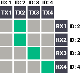
»SET /SYS/MB/PHY.VideoChannelId=2
«pw /SYS/MB/PHY.VideoChannelId=2
The command above is sent to the RX1 Decoder.
6.16.2. Switching an Input to All Outputs

»SET /SYS/MB/PHY.VideoChannelId=2
«pw /SYS/MB/PHY.VideoChannelId=2
The command above is sent to all Decoders separately.
6.16.3. Switching the Source of a Video Wall

The source Encoder of an existing video wall (VW1) can be changed. In this case, the Video stream ID of the affected Decoders must be changed one-by-one.
»SET /SYS/MB/PHY.VideoChannelId=4
«pw /SYS/MB/PHY.VideoChannelId=4
The command above is sent to all Decoders in the Video wall.
INFO:The video wall properties are not changed by switching the Encoder. Each Decoder will show the same area of the (new) image as it had been set previously.
6.16.4. Multiple Switching

The commands have to be sent to the Decoders one-by-one, thus the switching is realized in practice by setting the Video stream ID of the Decoders to the same ID as the desired Encoders.
»SET /SYS/MB/PHY.VideoChannelId=4
«pw /SYS/MB/PHY.VideoChannelId=4
The command above is sent to RX1.
»SET /SYS/MB/PHY.VideoChannelId=3
«pw /SYS/MB/PHY.VideoChannelId=3
The command above is sent to RX2.
»SET /SYS/MB/PHY.VideoChannelId=2
«pw /SYS/MB/PHY.VideoChannelId=2
The command above is sent to RX3.
»SET /SYS/MB/PHY.VideoChannelId=1
«pw /SYS/MB/PHY.VideoChannelId=1
The command above is sent to RX4.
6.17. EDID Management (Encoder)
The Advanced EDID Management is available also by sending LW3 protocol commands. The structure of the EDID memory can be found in the The EDID Memory Structure section.
6.17.1. Querying the Emulated EDID
»GET•/EDID.EdidStatus
«pr•/EDID.EdidStatus=<EDID_mem_loc>:E1
Parameters
|
Identifier |
Parameter description |
Parameter values |
|
<EDID_mem_loc> |
The EDID memory location |
F1-F132: Factory preset EDIDs U1-U5: User presets D1: The EDID of the Display Device at the local output |
E1 means the Emulated EDID memory location (Input port).
INFO:There are empty slots in the Factory EDID range for future developments. See the Factory EDID List section.
Example
»GET /EDID.EdidStatus
«pr /EDID.EdidStatus=F47:E1
Explanation
F47 EDID (Factory #47) is currently emulated on the input port of the Encoder (E1).
6.17.2. Setting the Emulated EDID on the Input Port
Command and Response
»CALL•/EDID:switch(<source>:<destination>)
«mO•/EDID:switch
Parameters
|
Identifier |
Parameter description |
Parameter values |
|
<source> |
Source EDID memory location |
F1-F132: Factory preset EDIDs U1-U5: User presets D1: The EDID of the Display Device at the local output |
|
<destination> |
The emulated EDID memory of the input port |
E1 |
Example
»CALL /EDID:switch(F49:E2)
«mO /EDID:switch
Command and Response
»CALL•/EDID:copy(<source>:<destination>)
«mO•/EDID:copy
Parameters
|
Identifier |
Parameter description |
Parameter values |
|
<source> |
Source EDID memory location |
F1-F132: Factory preset EDIDs U1-U5: User presets D1: The EDID of the Display Device at the local output |
|
<destination> |
The desired User EDID location |
U1-U5 |
Example
»CALL /EDID:copy(D1:U1)
«mO /EDID:copy
Explanation
The EDID of the last connected sink (HDMI output, D1) has been copied to U1 User memory slot.
6.17.4. Querying the Preferred Resolution of an EDID
Command and Response
»GET•/EDID/<EDID_mem>/<EDID_mem_loc>.PreferredResolution
«pr•/EDID/<EDID_mem>/<EDID_mem_loc>.PreferredResolution=<Resolution>
Parameters
|
Identifier |
Parameter description |
Parameter values |
|
<EDID_mem> |
The desired EDID memory type |
F: Factory preset EDIDs U: User presets D: EDID from a connected display device E: Emulated EDID |
|
<EDID_mem_loc> |
The desired EDID memory location |
F1-F132: Factory preset EDIDs U1-U5: User presets D1: The EDID of the Display Device at the local output E1: The emulated EDID at the input |
|
<Resolution> |
The preferred resolution in the indicated format |
<width>x<height><scan_mode><refresh_rate>Hz <scan_mode>: p (progressive), i (interlaced) |
Example
»GET /EDID/U/U2.PreferredResolution
«pr /EDID/U/U2.PreferredResolution=1920x1080p60.00Hz
INFO:Use the Manufacturer property to query the manufacturer, and the MonitorName property to query the name of the monitor.
6.17.5. Deleting an EDID from the User Memory
Command and Response
»CALL•/EDID:delete(<User_loc>)
«mO•/EDID:delete
Parameters
|
Identifier |
Parameter description |
Parameter values |
|
<User_loc> |
User EDID location |
U1-U5 |
Example
»CALL /EDID:delete(U1)
The devices can be updated via the built-in web page, or by the Lightware Device Updater v2 (LDU2) software. The software is available at www.lightware.com. In order to get the firmware pack with the necessary components (*.lfp or *.lfp2 file) for your specific product, please contact support@lightware.com.
7.1. Built-in Web or LDU2
The firmware of the VINX device can be updated via two ways. The following table contains the features of the methods:
|
Function |
Built-in Web |
LDU2 |
|
Platform |
Mozilla Firefox, Google Chrome |
Windows, mac OS |
|
Installation |
Web browser needed only |
Required |
|
LFP file support |
|
- |
|
LFP2 file support |
|
|
|
Log export |
- |
|
7.2. Important Notices – Before Starting the Update
▪Update all VINX devices within a system. Make sure that the same firmware runs on the devices. If the firmwares are different, the seamless operation is not guaranteed.
▪While the firmware is being updated, signal processing is not performed. The normal operation mode is suspended, as the device is switched to bootload mode.
▪Do not interrupt the firmware update. If any problem occurs, reboot the device and restart the process.
▪The settings and parameters (e.g. User EDID memory, video wall settings) will not be lost by updating the firmware.
7.3. About the Firmware Package (LFP/LFP2 File)
The firmware files are packed in an LFP/LFP2 package. You need only this file to do the update in your device.
▪The package contains all the necessary components, binary, and other files; You do not have to get further files.
▪There is a descriptor file in the package that contains each firmware with version number, and a list showing the compatible devices, which is displayed in Lightware Device Updater v2 (LDU2) after loading.
7.4. Option 1. – Updating via the Built-in Web Page
WARNING!Never disconnect the power source from the VINX devices during the update! Interrupting the firmware update may cause the device to become unusable.
This method is available by the built-in web page of the VINX device. We recommend this way of update if you do not have the chance to install a software, or you have just a few devices.
7.4.1. Firmware Updating Steps
Step 1.Get the necessary firmware pack (*.lfp or *.lfp2 file) and save it to the control device (computer/mobile device).
Step 2.Establish the connection from the computer/mobile device to the desired VINX extender as described in the Connecting via the Built-in Web Page.
Step 3.Navigate to the Advanced Settings tab.
Step 4.Locate the Update Firmware section and press the Choose file button. Browse the firmware package file and press OK.


Firmware Update via the Built-in Web Page
Step 5.Press the Update Firmware button. The firmware pack will be uploaded into the device, and the update process is started automatically.
Step 6.The progress bar and a short label will show the current state of the process.
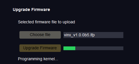
Step 7.When the programming is finished, the device will reboot and the connection will be lost. Powering the device off and on again is recommended.
INFO:LFP and LFP2 packages are also accepted for updating via the built-in web.
7.5. Option 2. – Updating by LDU2
7.5.1. Introduction

Lightware Device Updater v2 (LDU2) software is the second generation of the LFP-based (Lightware Firmware Package) firmware update process.
DIFFERENCE:The software can be used for uploading the packages with LFP2 extension only. LDU2 is not suitable for using LFP files, please use the LDU software for that firmware update.
7.5.2. Preparation
Most Lightware devices can be controlled over several interfaces (e.g. Ethernet, USB, RS-232). But the firmware can usually be updated over one dedicated interface, which is the Ethernet in most cases.
If you want to update the firmware of one or more devices, you need the following:
▪LFP2 file,
▪LDU2 software installed on your PC or Mac.
Both can be downloaded from www.lightware.com/downloads.
Optionally, you can download the release notes file in HTML format.
7.5.3. About the Firmware Package (LFP2 File)
All necessary tools and binary files are packed into the LFP2 package file. You need only this file to do the update on your device.
▪This allows the use of the same LFP2 package for different devices.
▪The package contains all the necessary components, binary, and other files.
▪The release notes is included in the LFP2 file, which is displayed in the window where you select the firmware package file in LDU2.
7.5.4. LDU2 Installation
ATTENTION!Minimum system requirement: 2 GB RAM. The minimum display resolution is 1600x900.
INFO:The Windows and the Mac applications have the same look and functionality.
Download the software from www.lightware.com/downloads.
Installation in case of Windows OS
Run the installer. If the User Account Control displays a pop-up message, click Yes.
Installation Modes
|
Normal install |
Snapshot install |
|
Available for Windows, MacOS and Linux |
Available for Windows |
|
The installer can update only this instance |
Cannot be updated |
|
One updateable instance may exist for all users |
Many different versions can be installed for all users |
ATTENTION!Using the default Normal install is highly recommended.
INFO:If you have a previously installed version, you will be prompted to remove the old version before installing the new one.
Installation in case of macOS
Mount the DMG file by double clicking on it, and drag the LDU2 icon over the Applications icon to copy the program into the Applications folder. If you want to copy LDU2 into another location, just drag the icon over the desired folder.
ATTENTION!Please check the firewall settings on the macOS device. LDC needs to be added to the exeptions of the blocked softwares for the proper operation.
INFO:This type of installer is equal with the Normal install of Windows.
Installation in case of Linux

Step 1.Download the archive file (tar.gz) from www.lightware.com and unpack it to a temp folder.
Step 2.Run the install_ldu2.sh file in the temp folder. The script will install LDU2 into the following folder: HOME/.local/share/lightware/ldu2.
Step 3.The folder above will contain this file: LightwareDeviceUpdaterV2.sh, which can be used to start LDU2.
7.6. Running the Software
You have two options:
▪Starting the LDU2 by double-clicking on the shortcut/program file, or
▪Double-clicking on an LFP2 file.
LDU2 Auto-Update
At startup, the software checks if a newer version is available on the web.

Main Screen

When the software is started by the shortcut, the device discovery screen appears. Press the Discover devices button to start finding the Lightware devices:

Devices may also be added manually by typing the IP address in the box near the bottomof the screen. From LDU2 version v2.16.1, manual addition of devices can also be done using the hostname.
ATTENTION!If the device cannot be added by the hostname, please use the IP address.
If you start the software by double-clicking on the LFP2 file, the firmware will be loaded. Press the Discover devices button; all the devices will be listed that are compatible with the selected firmware pack.
INFO:If you press the Select package file button, the release notes of the LFP2 file will be displayed in the right panel; see the Step 1. Select the Firmware Package. section.
Device List
When the discovery has completed, the devices available on the network are listed in the application.

Legend of the Icons
|
|
IP address editor |
The IP address of the device can be changed in the pop-up window. |
|
|
Identify me |
Clicking on the icon results the front panel LEDs blinking for 10 seconds, which helps identify the device physically. |
|
|
Favorite device |
The device has been marked, thus the IP address is stored. When a device is connected with that IP address, the star will be highlighted in that line. |
|
|
Further information available |
Device is unreachable. Change the IP address using the front panel LCD menu or the IP address editor of the LDU2. |
|
|
Cleartext login enabled |
The password-protection is enabled. You have to enter the password to perform the firmware update in the Update options window, or in the appearing window in the beginning of the update. |
|
|
Service mode |
The device is in bootload mode. Backup and restore cannot be performed in this case. |

7.7. The Updating Steps
ATTENTION!While the firmware is being updated, the normal operation mode is suspended, as the device is switched to bootload mode. Signal processing is not performed. Do not interrupt the firmware update. If any problem occurs, reboot the unit and restart the process.
Keeping the Configuration Settings
By default, device configuration settings are restored when the firmware update is finished. If factory reset has been chosen in the parameters window, all device settings will be erased. In the case of factory reset, you can save the settings of the device in the Lightware Device Controller software and restore it later.
The following flow chart demonstrates how this function works in the background.
Step 1.Create a backup
The current configuration of the device is being saved into a configuration backup file on your computer.
Step 2.Start the Update
The device reboots and starts in bootload mode (firmware update mode).
Step 3.Update
The CPU firmware is changed to the new one.
Step 4.Factory reset
All configuration settings are restored to the factory default values.
Step 5.Conversion / Restore
The firmware package checks the backup data before the restoration procedure, and if it is necessary, a conversion is applied to avoid incompatibility problems between the firmware versions. All configuration settings are restored to the device after the conversion.
If the factory default option is selected in the Parameters window, the conversion / restoration procedure will not be performed!
Step 6.Finish
Once the firmware update procedure is finished, the device reboots and is ready to use.
Step 1. Select the Firmware Package.

Press the Choose Package File button, and navigate to the location where the LFP2 file was saved. When you click on the name of package, the preview of the release notes are displayed in the right panel.

After the package file is loaded, the list is filtered to show the compatible devices only. The current firmware version of the device is highlighted in orange if it is different from the version of the package loaded.

INFO:If you start the update by double-clicking on the LFP file, the screen above will be loaded right away.
Step 2. Select the desired devices for updating.
Select the devices for updating; the selected line will be highlighted in green.

Step 3. Check the update parameters.

DIFFERENCE:The appearing settings are device-dependent and can be different from device to device.
Clicking on the Update options button, special settings will be available, like:
▪Creating a backup about the configuration,
▪Restoring the configuration or reloading the factory default settings after the firmware update,
▪Uploading the default Miniweb (if available)
▪Enter the password for the Cleartext login. #builtinweb #miniweb #web
INFO:The password entered here will be used for all selected devices where the Cleartext login is enabled. If the password is incorrect, a window will appear to ask for the correct one for each device during the update.
Please arrange the settings carefully.
Step 4. Start the update and wait until it is finished.

Click on the Start Update button to start the procedure. The status is shown in percent in the right side of the device line, and the overall process in the bottom progress bar.
INFO:The device might reboot during the firmware update procedure.

When the progress bar reaches 100% (Done is displayed at all devices), the update of all devices are finished successfully and a message appears; you can close the software.

Step 5. Wait until the unit reboots with the new firmware.
Once the firmware update procedure is completed, the device is rebooted with the new firmware. Shutting down and restarting the device is recommended.
7.8. Command Line Interface (CLI)
DIFFERENCE:The Command Line Interface is available from LDU2 v2.9.0b9.
The CLI of the LDU2 software is a simple tool for creating scriptable device updates without the need for human interactions. It allows batch updating with the same features that are available in the case of GUI usage.
7.8.1. How to Run
Running under Windows® OS
The installer of LDU2 puts the following file into the installation folder:
LightwareDeviceUpdaterV2_CLI.cmd
CLI is available via this file, the exe is not suitable for that purpose. Open a command line window to execute or test the features directly.
Step 1.Open an Explorer window where the cmd file is located, the default is:
c:\Program Files (x86)\Lightware\Lightware Device Updater V2\LightwareDeviceUpdaterV2_CLI.cmd.
Step 2.Click on the address line (highlighed in blue in the picture), type cmd.exe and press enter. The command interpreter window of Windows is opened at the path of the LDU2 install folder.

Step 3.Now you can use the LightwareDeviceUpdaterV2_CLI.cmd file with the commands and options that are described in the coming sections:
Running under Linux
The Command Line Interface under Linux Operating Systems can be run by the following:
LightwareDeviceUpdaterV2.sh.
Running an update:
bash LightwareDeviceUpdaterV2.sh update --ip 172.24.5.27 --package ~/Downloads/vinx_v3.1.0b4.lfp2
The commands and options are the same under Windows® and Linux, too. The following sections contain examples with LightwareDeviceUpdaterV2_CLI.cmd.
7.8.2. How to Use
Command Structure
The commands can be run over CLI in the following way:
LightwareDeviceUpdaterV2_CLI.cmd [command] [options]
[Command]: a certain command described in the coming sections; only one command can be run at a time
[Options]: mandatory and/or optional parameters of the command, if any. Optional parameters have a default value, which can be found at each affected command. You only have to define the parameter if you want to apply a different value. The order of the options is arbitrary.
Important Notes
▪CLI is case-sensitive (including commands, options and other parameters).
▪There is no limit regarding the number of the devices to update. At most 20 devices are updated simoultaneously, when one of them is finished, the following (21st) will be started automatically.
▪If an update is failed, the IP address of the affected device(s) are listed at the end.
7.9. CLI Commands
INFO:The commands and options described in the following sections are the same under Windows® and Linux, too. The examples contain LightwareDeviceUpdaterV2_CLI.cmd.
About the Examples
▪Sent command is in blue, response is in grey.
▪If the response in practice is longer than listed in the example, this symbol can be seen: [...].
7.9.1. Help
The defined commands and options can be listed by the help command.
Command
LightwareDeviceUpdaterV2_CLI.cmd help
Example
C:\Program Files (x86)\Lightware\Lightware Device Updater V2>LightwareDeviceUpdaterV2_CLI.cmd help
C:\Program Files (x86)\Lightware\Lightware Device Updater V2>lib\jre\bin\java.exe -jar lib\ldu2.jar help
Command line usage:
Win: LightwareDeviceUpdaterV2_CLI.cmd [command] [options]
Linux: LightwareDeviceUpdaterV2.sh [command] [options]
Commands:
* help
* version
* update
* deviceInfo
* restore
* packageOptions
[...]
7.9.2. LDU2 Version
The response shows the version of the LDU2 and the version of the Script API (the Application Programming Interface that is used by the LDU2 and the script).
Command
LightwareDeviceUpdaterV2_CLI.cmd version
Example
C:\Program Files (x86)\Lightware\Lightware Device Updater V2>LightwareDeviceUpdaterV2_CLI.cmd version
C:\Program Files (x86)\Lightware\Lightware Device Updater V2>lib\jre\bin\java.exe -jar lib\ldu2.jar version
LDU2 version: 2.14.0b5
Script API version: 1.3.13
7.9.3. Check For New LDU2 Version
The following command can be used to check if an update of LDU2 is available. This is just a request, since the CLI is not suitable for handling the complete installation of the software.
Command
LightwareDeviceUpdaterV2_CLI.cmd checkForUpdates
Example 1
C:\Program Files (x86)\Lightware\Lightware Device Updater V2>LightwareDeviceUpdaterV2_CLI.cmd checkForUpdates
C:\Program Files (x86)\Lightware\Lightware Device Updater V2>lib\jre\bin\java.exe -jar lib\ldu2.jar checkForUpdates
Current LDU2 version: 2.14.0b5
LDU2 is up-to-date
Example 2
c:\Program Files (x86)\Lightware\Lightware Device Updater V2>LightwareDeviceUpdaterV2_CLI.cmd checkForUpdates
c:\Program Files (x86)\Lightware\Lightware Device Updater V2>lib\jre\bin\java.exe -jar lib\ldu2.jar checkForUpdates
Current LDU2 version: 2.13.1b4
New version is available online: v2.14.0b5
Download URL: http://update.lightware.hu/ldu2/lwr/v2.14.0b5/install_LDU2_v2.14.0b5.exe
7.9.4. Device Info
The most important information about the selected device is displayed; see the example for more details.
Command
LightwareDeviceUpdaterV2_CLI.cmd deviceInfo [options]
Options
|
Option |
Description |
Required? |
|
-i or --ip |
List of IP addresses of devices to be updated |
one of them is mandatory |
|
-n or --hostName |
List of host names of devices to be updated |
|
|
-v or --packageVersion |
Shows installed package version only |
optional |
Example 1
C:\Program Files (x86)\Lightware\Lightware Device Updater V2>LightwareDeviceUpdaterV2_CLI.cmd deviceInfo --ip 192.168.0.110
C:\Program Files (x86)\Lightware\Lightware Device Updater V2>lib\jre\bin\java.exe -jar lib\ldu2.jar deviceInfo --ip 192.168.0.110
Product name: WP-VINX-110P-HDMI-ENC
IP address: 192.168.0.110
Serial number: 808139
MAC address: 34:1B:22:80:81:39
Part number: 91810012
Device label: VINX-TX-808139
Package version: v3.0.1b8
CPU FW version: v3.0.1b3
HW version:
Operation mode: Application mode
Example 2
C:\Program Files (x86)\Lightware\Lightware Device Updater V2>LightwareDeviceUpdaterV2_CLI.cmd deviceInfo --ip 192.168.0.110 --packageVersion
C:\Program Files (x86)\Lightware\Lightware Device Updater V2>lib\jre\bin\java.exe -jar lib\ldu2.jar deviceInfo --ip 192.168.0.110 --packageVersion
v3.0.1b8
7.9.5. Update
This command can be used to update the firmware of the devices.
Command
LightwareDeviceUpdaterV2_CLI.cmd update [options]
Options
|
Option |
Description |
Required? |
|
-p or --package |
The path of the firmware package file |
yes |
|
-i or --ip |
List of IP addresses of devices to be updated |
one of them is mandatory |
|
-n or --hostName |
List of host names of devices to be updated |
|
|
-r or --reportProgress |
Report update progress in percentage form. Default: false |
optional |
Example
C:\Program Files (x86)\Lightware\Lightware Device Updater V2>LightwareDeviceUpdaterV2_CLI.cmd update --ip 192.168.1.7 --package C:\Firmwares\UMX-HDMI-140_v1.3.0b5.lfp2 --reportProgress
C:\Program Files (x86)\Lightware\Lightware Device Updater V2>lib\jre\bin\java.exe -jar lib\ldu2.jar update --ip 192.168.0.110 --package C:\Firmwares\vinx_v3.1.0b4.lfp2 --reportProgress
[2022-03-24 14:48:17.267] [ INFO] [ main] - Device IPs: [192.168.0.110]
[2022-03-24 14:48:19.400] [ INFO] [ main] - All selected devices are available over the network.
[2022-03-24 14:48:19.779] [ INFO] [ main] - All the selected devices are compatible with the specified package.
[2022-03-24 14:48:20.004] [ INFO] [ 192.168.0.110] - Version of the package: 3.1.0
[2022-03-24 14:48:20.293] [ INFO] [ 192.168.0.110] -
>>> Device IP: 192.168.0.110
>>> Product name: WP-VINX-110P-HDMI-ENC
>>> Part number: 91810012
>>> Serial number: 808139
>>> Device label: VINX-TX-808139
>>> Mac address: 34:1B:22:80:81:39
>>> Core FW version: v3.1.0b3 r2
>>> Package version: v3.1.0b4 r1
[2022-03-24 14:48:20.352] [ INFO] [ 192.168.0.110] - Uploading vinx.zip at: http://192.168.0.110/cgi-bin/astfwup.cgi
[2022-03-24 14:48:24.788] [ INFO] [ProgressReporter] - Progress: 6%
[2022-03-24 14:48:29.796] [ INFO] [ProgressReporter] - Progress: 10%
[2022-03-24 14:48:34.802] [ INFO] [ProgressReporter] - Progress: 12%
[2022-03-24 14:48:39.811] [ INFO] [ProgressReporter] - Progress: 14%
[2022-03-24 14:48:44.814] [ INFO] [ProgressReporter] - Progress: 16%
[2022-03-24 14:49:32.323] [ INFO] [ 192.168.0.110] - The device is starting to update itself...
[2022-03-24 14:49:37.476] [ INFO] [ 192.168.0.110] - Polling update_fw_result.txt...
[2022-03-24 14:54:29.924] [ INFO] [ProgressReporter] - Progress: 27%
[2022-03-24 14:54:54.932] [ INFO] [ProgressReporter] - Progress: 28%
[2022-03-24 14:55:29.946] [ INFO] [ProgressReporter] - Progress: 29%
[2022-03-24 14:55:54.949] [ INFO] [ProgressReporter] - Progress: 30%
[2022-03-24 14:56:24.952] [ INFO] [ProgressReporter] - Progress: 31%
[2022-03-24 14:56:49.955] [ INFO] [ProgressReporter] - Progress: 32%
[2022-03-24 14:57:19.957] [ INFO] [ProgressReporter] - Progress: 33%
[2022-03-24 14:57:49.961] [ INFO] [ProgressReporter] - Progress: 34%
[2022-03-24 14:58:09.633] [ INFO] [ 192.168.0.110] - Self-update process is DONE
[2022-03-24 14:58:09.964] [ INFO] [ProgressReporter] - Progress: 85%
[2022-03-24 14:58:29.095] [ INFO] [ 192.168.0.110] - Rebooting...
[2022-03-24 14:58:29.099] [ INFO] [ 192.168.0.110] - Trying to reconnect after device reset over LW3. #1.0
[2022-03-24 14:58:29.973] [ INFO] [ProgressReporter] - Progress: 90%
[2022-03-24 14:58:43.294] [ INFO] [ 192.168.0.110] - Trying to reconnect after device reset over LW3. #2.0
[2022-03-24 14:58:57.524] [ INFO] [ 192.168.0.110] - Trying to reconnect after device reset over LW3. #3.0
[2022-03-24 14:59:11.756] [ INFO] [ 192.168.0.110] - Trying to reconnect after device reset over LW3. #4.0
[2022-03-24 14:59:25.963] [ INFO] [ 192.168.0.110] - Trying to reconnect after device reset over LW3. #5.0
[2022-03-24 14:59:40.179] [ INFO] [ 192.168.0.110] - Trying to reconnect after device reset over LW3. #6.0
[2022-03-24 14:59:40.222] [ INFO] [ 192.168.0.110] - Reconnected to device. Device uptime: 72.0
[2022-03-24 14:59:40.268] [ INFO] [ 192.168.0.110] - Package version on device is verified.
[2022-03-24 14:59:40.268] [ INFO] [ 192.168.0.110] - Device update complete!
[2022-03-24 14:59:40.269] [ INFO] [ 192.168.0.110] - Done
All 1 update(s) finished successfully.
The lines containing "ProgressReporter" can be enabled optionally. If it is enabled, the current state is displayed for every step in the update procedure..
7.9.6. Exit Codes
There is a return value in all cases when a command run is finished. Currently, three codes are defined:
|
Code |
Displayed text |
Description |
|
0 |
N/A |
The update performed successfully |
|
1 |
Update error (ErrorCode:1) |
The error happened during the update |
|
2 |
CLI error (ErrorCode:2 |
The error happened before starting the update |
The error line contains further information about the error.
Querying the Exit Code under Windows®
c:\Program Files (x86)\Lightware\Lightware Device Updater V2\echo %errorlevel%
0
Querying the Exit Code under Linux
echo $?
0
If this value is queried after the update and it is 0, the update was performed successfully.
7.10. If the Update is not succesful
▪Restart the process and try the update again.
▪If the device cannot be switched to bootload (firmware update) mode, you can do that manually as written in the User's manual of the device. Please note that backup and restore cannot be performed in this case.
▪If the backup cannot be created for some reason, you will get a message to continue the process without backup or stop the update. A root cause can be that the desired device is already in bootload (firmware update) mode, thus the normal operation mode is suspended and backup cannot be made.
▪If an update is not succesful, the Export log button becomes red. If you press the button, you can download the log file as a ZIP package, which can be sent to Lightware Support if needed. The log files contain useful information about the circumstances to find the root cause. #bootload
Usually, if the system seems not to transport the signal as expected, the best strategy for troubleshooting is to check signal integrity through the whole signal chain starting from source side and moving forward to receiver end.
Pictogram Legend

|
Link to the section of connections/cabling. |

|
Link to the section of front panel operation. |

|
Link to the section of the built-in web page. |

|
Link to the section of LW3 protocol commands. |
The following sections are available in the chapter:
8.1. Use Cases
At first, check front panel LEDs and take the necessary steps according to their states. For more information about front and rear panel LEDs of the devices, refer to the VINX-120-HDMI-ENC and VINX-110-HDMI-DEC sections.
|
Symptom |
Root cause |
Action |
Refer to |
|
|
Video issues |
||||
|
No video on the screen |
No video signal on the input. |
Check the source and the cable connections. |
|
|
|
The Video Stream IDs are different. |
Check the settings of the extenders and assign them. |
|
||
|
HDCP is disabled (EDID information cannot be read) |
Enable the HDCP on the input of the Encoder. (In certain cases, the source device cannot read the EDID from the Encoder.) |
|
||
|
HDCP-encrypted content sent to a non-HDCP sink. |
Replace the sink to a HDCP-capable one. |
|||
|
Network issues |
||||
|
Cannot connect to an extender |
The extenders did not get IP address. |
The Ethernet switch needs more time to be ready than the extenders. Reboot the VINX devices. |
||
|
The extender is not connected. |
Check the LEDs and the cable connections. |
|
||
|
The extenders and the PC are not in the same subnet. |
Make sure the devices are located in the same subnet. |
|||
|
USB issues |
||||
|
The video stream cannot be changed by the keyboard shortcut |
The keyboard is connected to an USB 2.0 port. |
Connect the keyboard to the USB 1.1 port. |
|
|
|
Shortcut is not assigned properly. |
Check the settings and set the shortcut(s) again. |
|
||
|
The keyboard is connected to another Decoder. |
Connect it to the desired Decoder. |
|
||
|
USB data transmission does not work |
Another Decoder is selected for USB transmission. |
Check the LEDs or the USB settings in the built in web page. |
|
|
|
|
||||
|
The Encoder and the computer are not connected over USB. |
Connect the supplied USB cable between the computer and the Encoder. |
|
||


8.2. How to Speed Up the Troubleshooting Process

Lightware’s technical support team is always working hard to provide the fastest support possible. Our team’s response time is one of the best in the industry, and in the toughest of cases we can directly consult with the hardware or software engineer who designed the product to get the information from the most reliable source.
However, the troubleshooting process can be even faster… with your help.
There are certain pieces of information that push us in the right direction to find the root cause of the problem. If we receive most of this information in the first e-mail, or it is gathered at the time when you call us, then there is a pretty high chance that we will be able to respond with the final solution right away. This information is the following:
▪Schematic (a pdf version is preferred, but a hand drawing is sufficient).
▪Serial number(s) of the device(s) (it is either printed somewhere on the box or you can query it in the Device Controller software or on the built-in website).
▪Firmware versions of the devices (please note that there may be multiple CPUs or controllers in the device and we need to know all of their firmware versions, a screenshot is the best option).
▪Cable lengths and types (in our experience, it’s usually the cable).
▪Patch panels, gender changers or anything else in the signal path that can affect the transmission.
▪Signal type (resolution, refresh rate, color space, deep color).
▪Emulated EDID(s) (please save them as a file and send it to us).
▪Actions to take in order to re-create the problem (if we cannot reproduce the problem, it is hard for us to find the cause).
▪Photo or video about the problem (‘image noise’ can mean many different things, it’s better if we see it too).
▪Error logs from the Device Controller software.
▪In the case of Event Manager issue, the event file and/or backup file from the Device Controller software.
▪The more of the information above you can give us, the better. Please send this information to the Lightware Support Team (support@lightware.com) to speed up the troubleshooting process.
The following sections contain descriptions and useful technical information on how the devices work in the background. The content is based on experiences and cases we met in the practice. These sections help to understand features and technical standards like the following:
The Extended Display Identification Data (EDID) is the passport of display devices (monitors, TV sets, projectors). It contains information about the capabilities of the display, such as supported resolutions, refresh rates (these are called Detailed Timings), the type and manufacturer of the display device, etc.
After connecting a source to a display (DVI, HDMI, DP), the source reads out the EDID to determine the resolution and refresh rate of the image to be transmitted.
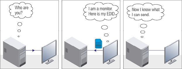
EDID Communication
Most DVI computer displays have a 128-byte-long EDID structure. However, Digital Televisions and HDMI capable displays may have another 128 bytes, which is called E-EDID and defined by CEA (Consumer Electronics Association). This extension contains information about additional Detailed Timings, audio capabilities, speaker allocation and HDMI capabilities. It is important to know that all HDMI capable devices must have CEA extension, but not all devices with CEA extension are HDMI capable.
Common Problems Related to EDID
Problem: “My system consists of the following: a computer, a Lightware device, a WUXGA (1920x1200) LCD monitor, and an SXGA (1280x1024) projector. I would like to see the same image on the monitor and the projector. What EDID should I choose on the Lightware device?”
Solution: If you want to see the image on both displays, you need to select the resolution of the smaller display (in this case SXGA), otherwise the smaller display may not show the higher resolution image.
Problem: “I have changed to a different EDID on an input port of the Lightware device to have a different resolution, but nothing happens.”
Solution: Some graphics cards and video sources read out the EDID only after power-up, and later they do not sense that the EDID has been changed. You need to restart your source to make it read out the EDID again.
9.1.2. Advanced EDID Management
Each DVI sink (e.g. monitors, projectors, plasma displays, etc...) must support the EDID data structure. Source BIOS and operating systems are likely to query the sink using DDC2B protocol to determine what pixel formats and interface are supported. DVI standard uses EDID data structure to identify the monitor type and capabilities. Most DVI sources (VGA cards, set top boxes, etc.) will output DVI signal after accepting the connected sink’s EDID information. In the case of EDID readout failure or missing EDID, the source will not output DVI video signal.
Lightware devices provide the Advanced EDID Management function that helps system integration. The built-in EDID Router can store and emulate factory pre-programmed- and User programmable EDIDs. The EDID of the attached monitors or projectors for each output are stored in a non-volatile memory. This way, the EDID of a monitor is available when the monitor is unplugged or switched off.
Any EDID can be emulated on any input. An emulated EDID can be copied from the EDID router’s memory (static EDID emulation), or from the last attached monitor’s memory (dynamic EDID emulation). For example, the Lightware device can be set up to emulate a sink device, which is connected to one of the outputs. In this case, the EDID automatically changes if the monitor is replaced with another display device (as long as it has a valid EDID).
The EDID is independently programmable for all inputs without affecting each other. All inputs have their own EDID circuit.
INFO:The user is not required to disconnect the video cable to change an EDID as opposed to other manufacturer’s products. The EDID can be changed even if a source is connected to the input and powered ON.
INFO:When the EDID has been changed, the router toggles the HOTPLUG signal for 2 seconds. Some sources do not sense this signal. In such cases, the source device must be restarted or powered OFF and ON again.
9.2. AV Over IP
Basics
Beside the traditional AV matrix switchers and extenders, the video over IP or networked AV system is the biggest leading technology in the AV industry. The spreading of the technology speeds up the general increasing of the use of the IT-related devices and equipment all around the world - from the offices to the homes.
The main difference compared to the traditional AV technologies is the method of the signal transmission: the networked AV transmitter/encoder devices convert the video signal to TCP/IP packets and transfer them to the receivers/decoders. The interface of the transmission can be CATx or fiber optical cable, depending on the signal bandwidth and the distance between the source and sink devices.
What is TCP/IP?
DEFINITION:TCP/IP, or the Transmission Control Protocol/Internet Protocol, is a suite of communication protocols used to interconnect network devices on the Internet or in a private network.
TCP/IP specifies how data is exchanged over the network by providing end-to-end communications that identify how it should be broken into packets, addressed, transmitted, routed and received at the destination. TCP/IP requires little central management, and it is designed to make networks reliable, with the ability to recover automatically from the failure of any device on the network. *
The two main protocols in the Internet protocol suite serve specific functions. TCP defines how applications can create channels of communication across a network. It also manages how a message is assembled into smaller packets before they are then transmitted over the Internet and reassembled in the right order at the destination address. *
IP defines how to address and route each packet to make sure it reaches the right destination. Each gateway computer on the network checks this IP address to determine where to forward the message. *
* Source: https://searchnetworking.techtarget.com/definition/TCP-IP
Lightware Visual Engineering is a legal HDCP adopter. Several functions have been developed, which helps to solve HDCP related problems. Complex AV systems often have both HDCP and non-HDCP components. The matrix allows transmitting HDCP encrypted and unencrypted signals. The devices will be still HDCP compliant, as they will never output an encrypted signal to a non-HDCP compliant display device. If an encrypted signal is switched to a non-compliant output, a red screen alert or muted screen will appear.
9.3.1. Protected and Unprotected Content
Many video sources send HDCP protected signal if they detect that the sink is HDCP capable – even if the content is not copyrighted. This can cause trouble if an HDCP capable device is connected between the source and the display. In this case, the content cannot be viewed on non-HDCP capable displays and interfaces like event controllers. Rental and staging technicians often complain about certain laptops, which are always sending HDCP encrypted signals if the receiver device (display, matrix router, etc.) reports HDCP compliancy. Even though HDCP encryption is not required all the time (e.g. computer desktop image), certain laptops still do that.
To avoid unnecessary HDCP encryption, Lightware introduced the HDCP enabling/disabling function: the HDCP capability can be disabled in the Lightware device. If HDCP is disabled, the connected source will detect that the sink is not HDCP capable, and turn off authentication.
9.3.2. Disable Unnecessary Encryption
HDCP Compliant Sink
All the devices are HDCP-compliant, no manual setting is required, both protected and unprotected contents are transmitted and displayed on the sink.

Not HDCP-compliant Sink 1.
Not-HDCP compliant sink is connected to the matrix. Some sources (e.g. computers) always send HDCP encrypted signals if the receiver device reports HDCP compliancy, however, HDCP encryption is not required all the time (e.g. computer desktop image). If HDCP is enabled in the matrix, the image will not be displayed on the sink.
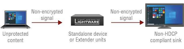
Setting the HDCP parameter to Auto on the output port and disable HDCP on the input port, the transmitted signal will not be encrypted if the content is not protected. Thus, non-HDCP compliant sinks will display non-encrypted signal.
Not HDCP-compliant Sink 2.
The layout is the same as in the previous case: non-HDCP compliant display device is connected to the matrix but the source would send protected content with encryption. If HDCP is enabled on the input port of the matrix, the source will send encrypted signal.

The sink is not HDCP compliant, thus it will not display the video signal, but blank screen is shown. If HDCP is disabled on the input port of the matrix, the source will not send the signal. The solution is to replace the display device with an HDCP-capable one.
9.3.3. HDCP v2.2
HDCP v2.2 is the latest evolution of copy protection. It is designed to create a secure connection between a source and a display. The 2.x version of HDCP is not a continuation of HDCPv1, and is rather a completely different link protection. One of the main differences is the number of the allowed devices within a closed A/V system: HDCP v2.2 allows 32 devices (HDCP v1.4 allows 128 devices). A further limit is that up to four level is allowed, which means the protected signal can be transmitted over at most four repeater/matrix/switcher devices. HDCP content protection is activated only if an active video stream is transmitted from the source to the display. The encryption is not activated without a video signal.
HDCP v2.2 standard allows the application of a previous version of HDCP (e.g. HDCP v1.4) between the source and the display if the source device allows it. According to the standard, if the image content is protected with HDCP, the highest supported content protection level has to be applied. However, if the highest level of protection is not justified by the source content, the level may be decreased to avoid compatibility problems; this case is determined by the source.
HDCP v2.2 Source and HDCP v1.4 Sink
In this case the signal of an HDCP v2.2 compliant source is switched to an HDCP v1.4 compliant sink device. The signal is encrypted with HDCP v2.2 on the input and encrypted with HDCP v1.4 on the output of the Lightware device. A lower level of encryption may be applied only if the source device/content allows it - according to the HDCP standard. In this case, the HDCP setting on the input port has to be set to HDCP 1.4 and Depends on input on the output port.
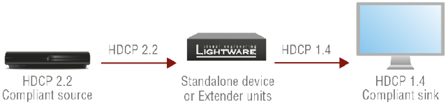
HDCP v1.4 Source and HDCP v2.2 Sink
The example below is the reversal of the previous case. An HDCP v1.4 compliant source sends a signal with HDCP v1.4 encryption. The signal is switched to an HDCP v2.2 compliant sink device. In this case, the outgoing signal has to be encrypted with the highest supported encryption level towards the sink, as the Lightware device and the sink are both HDCP v2.2 compliant. The HDCP v2.2 standard does not allow keeping the original HDCP v1.4 encryption level on the output.

What Kind of Signal Will be on the Output of the Lightware Device?
See the table below that summarizes the possible cases:
|
Incoming Signal |
HDCP v1.4 Compatible Sink |
HDCP v2.2. Compatible Sink |
|
HDCP v1.4 |
HDCP v1.4 |
HDCP v2.2 |
|
HDCP v2.2 (convertable)* |
HDCP v1.4 |
HDCP v2.2 |
|
HDCP v2.2 (not convertable)* |
Red screen |
HDCP v2.2 |
* Stream type 0: the video stream allows the conversion of the signal to apply a lower level of encryption.
** Stream type 1: the video stream does not allow the conversion of the signal.
9.4. RS-232 Signal Management (VINX AP-Series)
9.4.1. General Information
There are two types of devices in general serial communication:
▪Data Terminal Equipment: Data Terminal Equipment (DTE) is an end instrument that converts user information into signals or reconverts received signals. Typical DTE devices: computers, LCD touch panels and control systems.
▪Data Circuit-terminating Equipment: Data Circuit-terminating Equipment (DCE) is a device that sits between the DTE and a data transmission circuit. It is also called data communication equipment and data carrier equipment. Typical DCE devices: projectors, industrial monitors and amplifiers.
Among others, the pin assignment is different between DTE and DCE.
|
DTE |
DCE |
|
|
Pin 2: |
RD |
TD |
|
Pin 3: |
TD |
RD |
RD: Received Data (digital input)
TD: Transmitted Data (digital output)
Different type of serial cables must be used between different serial devices.
|
DTE |
DCE |
|
|
DTE |
Null-modem |
TD |
|
DCE |
Straight |
Null-modem* |
* In general, contact DCE with DCE by tail-circuit serial cable.
9.4.2. Types of Serial Cables
|
Straight Serial Cable |
Null-modem Serial Cable |
|
Straight pin-outs both ends. |
Straight pin-out at the one end and cross pin-out at the other end (interchange lines of TX and RX). |
|
|
|


Devices may have male or female plugs and their type can be straight or null-modem cables.
ATTENTION!The cable type does not depend on the plug type.
9.4.3. Serial Device Types
The types of VINX devices from serial data transmission point of view are the following:
|
VINX model |
Unit type |
|
VINX-120AP-HDMI-ENC, VINX-120AP-HDMI-ENC-DNT, VINX-210AP-HDMI-ENC |
DCE |
|
VINX-110AP-HDMI-DEC |
DTE |
9.4.4. RS-232 Signal Transmission over VINX Devices
The following examples show when source and sink devices are connected over Lightware's DCE- and DTE-type extenders for serial data transmission.
Data Tranmission from a DCE Source to a DCE Sink Device

Data Tranmission from a DCE Source to a DTE Sink Device

Data Tranmission from a DTE Source to a DCE Sink Device

Data Tranmission from a DTE Source to a DTE Sink Device

Tables, drawings, guides, and technical details as follows:
10.1. Specifications
DIFFERENCE:Valid for VINX-120-HDMI-ENC and VINX-110-HDMI-DEC devices.
General
|
Compliance |
CE, UKCA |
|
EMC (emission) |
EN 55032:2015+A1:2020 |
|
EMC (immunity) |
EN 55035:2017+A11:2020 |
|
RoHS |
EN 63000:2018 |
|
Electrical safety |
EN 62368-1:2020 |
|
Warranty |
3 years |
|
Operating temperature |
0° to +50˚C (+32° to +122˚F) |
|
Operating humidity |
10% to 90%, non-condensing |
|
Cooling |
Passive |
Power
|
Power supply option |
Power adaptor (supplied) |
VINX-110-HDMI-DEC
|
Power consumption (max) |
5W |
|
Heat dissipation (max) |
17 BTU/h |
VINX-120-HDMI-ENC
|
Power consumption (max) |
8.5W |
|
Heat dissipation (max) |
29 BTU/h |
Power adaptor
|
Supported power source |
100-240 V AC; 50/60 Hz |
|
Supplied power |
5 V DC, 3A |
|
AC power plug |
Interchangable (EU, UK, JP/US, AUS/NZ) |
|
DC power plug |
Locking DC connector (2.1/5.5 mm pin) |
Enclosure
|
Enclosure material |
1 mm steel |
|
Dimensions in mm |
100.4 W x 115 D x 26 H |
|
Dimensions in inch |
3.95 W x 4.53 D x 1.02 H |
|
Weight |
375 g |
Video Input
HDMI Input Port
|
Connector type |
19-pole HDMI type A receptacle |
|
A/V standard |
DVI 1.0, HDMI 1.4 |
|
HDCP Compliance |
Yes, v2.2 |
|
Color space |
RGB, YCbCr |
|
Supported resolutions at 8 bits/color |
up to 3840x2160@30Hz (4:4:4) or 3840x2160@60Hz (4:2:0); 1920x1080@60Hz (4:4:4) up to 12 bits/color |
|
3D signal support |
'Side-by-side' and 'Top-to-bottom' modes |
|
Audio formats |
Embedded LPCM, Dolby Digital 5.1 ch, Dolby Digital Plus, Dolby Digital Pro-Logic, Dolby TrueHD, DTS:X, Dolby Atmos, DTS 5.1 ch, DTS 96/24, DTS-ES Discrete, DTS-ES Matrix, DTS-HD High Resolution Audio, DTS-HD Master Audio |
Video Output
HDMI Output Port
|
Connector type |
19-pole HDMI type A receptacle |
|
A/V standard |
DVI 1.0, HDMI 1.4 |
|
HDCP Compliance |
v2.2 |
|
Color space |
RGB, YCbCr |
|
Supported resolutions at 8 bits/color |
up to 3840x2160@30Hz (4:4:4) or 3840x2160@60Hz (4:2:0), 1920x1080@60Hz (4:4:4) up to 12 bits/color |
|
3D signal support |
'Side-by-side' and 'Top-to-bottom' modes |
|
Audio formats |
Embedded LPCM, Dolby Digital 5.1 ch,, Dolby Digital Plus, Dolby Digital Pro-Logic, Dolby TrueHD, DTS:X, Dolby Atmos, DTS 5.1 ch, DTS 96/24, DTS-ES Discrete, DTS-ES Matrix, DTS-HD High Resolution Audio, DTS-HD Master Audio |
USB Ports
|
USB Port Type (Encoder) |
mini-B type receptacle |
|
USB Port Type (Decoder) |
type-A receptacle, 4 pcs. |
|
Data Communication Mode |
transparent |
RS-232 Ports
|
Connector type |
RJ12 female receptacle |
|
Baud rates |
300, 600, 1200, 2400, 4800, 9600, 19200, 38400, 57600, 115200 Baud |
|
Data bits |
6, 7, 8 |
|
Parity |
None / Odd / Even |
|
Stop bits |
1 / 2 |
|
Data Communication Mode |
Duplex, transparent |
Infrared Ports
|
Output connector type (Encoder) |
3.5 mm TS (1/8" jack) |
|
Input connector type (Decoder) |
3.5 mm TRS (1/8" jack) |
10.1.2. VINX AP-series
DIFFERENCE:The specification data below refer to the VINX-120AP-HDMI-ENC-DNT, VINX-120AP-HDMI-ENC, VINX-210AP-HDMI-ENC and VINX-110AP-HDMI-DEC devices.
General
|
Compliance |
CE, UKCA |
|
EMC (emission) |
EN 55032:2015+A1:2020 |
|
EMC (immunity) |
EN 55035:2017+A11:2020 |
|
RoHS |
EN 63000:2018 |
|
Electrical safety |
EN 62368-1:2020 |
|
Warranty |
3 years |
|
Operating temperature |
0° to +50˚C (+32° to +122˚F) |
|
Operating humidity |
10% to 90%, non-condensing |
|
Cooling |
Passive |
Power
|
Power supply option |
Power adaptor (supplied) / PoE |
|
Power over Ethernet (PoE) |
via AV in/out (IEEE802.3af) |
VINX-110AP-HDMI-DEC
|
Power consumption (max) |
5.2W |
|
Heat dissipation (max) |
18 BTU/h |
VINX-120AP-HDMI-ENC
|
Power consumption (max) |
7.5W |
|
Heat dissipation (max) |
25 BTU/h |
VINX-120AP-HDMI-ENC-DNT
|
Power consumption (max) |
8.2W |
|
Heat dissipation (max) |
28 BTU/h |
VINX-210AP-HDMI-ENC
|
Power consumption (max) |
8.3W |
|
Heat dissipation (max) |
28 BTU/h |
Power adaptor
|
Supported power source |
100-240 V AC; 50/60 Hz |
|
Supplied power |
12V DC, 1A DC |
|
AC power plug |
Interchangable (EU, UK, JP/US, AUS/NZ) |
|
DC power plug |
Locking DC connector (2.1/5.5 mm pin) |
Enclosure
|
Enclosure Material |
1 mm steel |
|
Dimensions in mm |
221W x 105.3D x 26H |
|
Dimensions in inch |
8.7W x 4.14D x 1.02H |
|
Weight |
665 g |
SFP Module Slot
|
Number of port |
1 |
|
Supported data rate |
1 Gbps |
|
Accepted interfaces |
SFP optical transceiver modules |
Video Input
HDMI Input Port
|
Connector type |
19-pole HDMI type A receptacle |
|
A/V standard |
DVI 1.0, HDMI 1.4 |
|
HDCP Compliance |
v2.2 |
|
Color space |
RGB, YCbCr |
|
Supported resolutions at 8 bits/color |
up to 3840x2160@30Hz (4:4:4) or 3840x2160@60Hz (4:2:0), 1920x1080@60Hz (4:4:4) up to 12 bits/color |
|
3D signal support |
'Side-by-side' and 'Top-to-bottom' modes |
|
Audio formats |
Embedded LPCM, Dolby Digital 5.1 ch, Dolby Digital Plus, Dolby Digital Pro-Logic, Dolby TrueHD, DTS:X, Dolby Atmos, DTS 5.1 ch, DTS 96/24, DTS-ES Discrete, DTS-ES Matrix, DTS-HD High Resolution Audio, DTS-HD Master Audio |
VGA Input Port
|
Connector type |
DE-15F (15-pole D-sub Female) |
|
Supported video signal |
Analog RGB and YPbPr video |
|
Color depth |
Up to 24 bits, 8 bit/color |
|
Max. resolution |
1680x1050@60 Hz |
Video Output
HDMI Output Port
|
Connector type |
19-pole HDMI Type A receptacle |
|
A/V standard |
DVI 1.0, HDMI 1.4 |
|
HDCP compliance |
HDCP 2.2 |
|
Color space |
RGB, YCbCr |
|
Supported resolutions at 8 bits/color |
up to 3840x2160@30Hz (4:4:4) or 3840x2160@60Hz (4:2:0), 1920x1080@60Hz (4:4:4) up to 12 bits/color |
|
Audio formats |
Embedded LPCM, Dolby Digital 5.1 ch, Dolby Digital Plus, Dolby Digital Pro-Logic, Dolby TrueHD, DTS:X, Dolby Atmos, DTS 5.1 ch, DTS 96/24, DTS-ES Discrete, DTS-ES Matrix, DTS-HD High Resolution Audio, DTS-HD Master Audio |
USB Ports
|
USB Port Type (Encoder) |
B type receptacle |
|
USB Port Type (Decoder) |
type-A receptacle, 4 pcs. |
|
Data Communication Mode |
transparent |
|
Data transmission rate (max) |
5 MBit/s |
RS-232 Ports
|
Serial Port Type |
DE-9 (9-pole D-sub) connector |
|
Baud rates |
300, 600, 1200, 2400, 4800, 9600, 19200, 38400, 57600, 115200 Baud |
|
Data bits |
6, 7, 8 |
|
Parity |
None / Odd / Even |
|
Stop bits |
1 / 2 |
|
Data Communication Mode |
Duplex, transparent |
Infrared Ports
|
Output connector type (Encoder) |
3.5 mm TS (1/8" jack) |
|
Input connector type (Decoder) |
3.5 mm TRS (1/8" jack) |
Analog Audio Input (VINX-120AP-HDMI-ENC and VINX-210AP-HDMI-ENC)
|
Connector type |
3.5mm TRS (1/8" jack) |
|
Audio formats |
2-ch PCM |
|
Sampling frequency |
44.1 – 192 kHz |
|
Signal transmission |
unbalanced signal |
|
Volume adjustment |
-44 – 0 dB |
Microphone Input (VINX-110AP-HDMI-DEC only)
|
Gain in the signal path * |
+20dB |
|
Peak level without distortion |
-2.5dBFS (3% THD) |
|
Total Harmonic Distortion (THD) |
0.08% (refl: -12DBFS, 1kHz) |
|
THD+Noise |
0.3% (approx. -60dBFS) |
|
Signal to Noise ratio (SNR) |
62dBFS |
|
Dynamic Range (DR) |
72dBFS |
|
Crosstalk |
100% (mono channel) |
|
Frequency response below 50Hz |
above -3dB |
* compared to the forward audio signal level. If this input is connected to a powered equipment, hum noise issue may occur. In this case an isolation transformer (a passive DI box) can help.
ATTENTION!The microphone input port applies a fixed bias to feed the connected electret (condenser) microphone. Thus, it is not suitable for dynamic microphones that do not contain isolation or an impedance matching transformer. (Danger of damage to the microphone.)
Analog Audio Output
|
Connector type |
3.5mm TRS (approx. 1/8" jack) |
|
Audio formats |
2-ch PCM |
|
Signal transmission |
unbalanced signal |
|
Sampling frequency |
44.1 kHz – 192 kHz |
|
Volume adjustment |
-44 – 0 dB |
|
Connector type |
RJ45 female connector |
|
Signal transmission |
Dante® or AES67 |
|
Supported channels |
2-channel stereo |
|
Sampling rates |
44.1, 48, 96 kHz |
10.1.3. WP/FP series
DIFFERENCE:Valid for WP-VINX-110P-HDMI-ENC and FP-VINX-series models.
General
|
Compliance |
CE, UKCA |
|
EMC (emission) |
EN 55032:2015+A1:2020 |
|
EMC (immunity) |
EN 55035:2017+A11:2020 |
|
RoHS |
EN 63000:2018 |
|
Electrical safety |
EN 62368-1:2020 |
|
Warranty |
3 years |
|
Operating temperature |
0° to +50˚C (+32° to +122˚F) |
|
Operating humidity |
10% to 90%, non-condensing |
|
Cooling |
Passive |
Power
|
Power supply option |
Power adaptor (optional accessory) / PoE |
|
Power over Ethernet (PoE) |
via AV in/out (IEEE802.3af) |
|
Power consumption (max) |
4.6W |
|
Heat dissipation (max) |
16 BTU/h |
Enclosure
|
Enclosure material |
1 mm steel |
|
Dimensions in mm (WP-VINX-110P-HDMI-ENC) |
116.3 W x 43.1 D x 115 H |
|
Dimensions in inch (WP-VINX-110P-HDMI-ENC) |
4.57 W x 1.7 D x 4.53 H |
|
Dimensions in mm (FP-VINX-series) |
116 W x 43 D x 77 H |
|
Dimensions in inch (FP-VINX-series) |
4.57 W x 1.69 D x 3.03 H |
|
Weight (WP-VINX-110P-HDMI-ENC) |
515 g |
|
Weight (FP-VINX-series) |
510 g |
Video Input
HDMI Input Port
|
Connector type |
19-pole HDMI type A receptacle |
|
A/V standard |
DVI 1.0, HDMI 1.4 |
|
HDCP Compliance |
HDCP 2.2 |
|
Color space |
RGB, YCbCr |
|
3D signal support |
'Side-by-side' and 'Top-to-bottom' modes |
|
Supported resolutions at 8 bits/color |
up to 4096x2160@30Hz (4:4:4) or 4096x2160@60Hz (4:2:0), up to 3840x2160@30Hz (4:4:4) or 3840x2160@60Hz (4:2:0), 1920x1080@60Hz (4:4:4) up to 12 bits/color |
|
Audio formats |
Embedded LPCM, Dolby Digital 5.1 ch, Dolby Digital Plus, Dolby Digital Pro-Logic, Dolby TrueHD, DTS:X, Dolby Atmos, DTS 5.1 ch, DTS 96/24, DTS-ES Discrete, DTS-ES Matrix, DTS-HD High Resolution Audio, DTS-HD Master Audio |
Video Output
|
Connector type |
RJ45 connector |
|
Power Over Ethernet |
yes (IEE 802.3af) |
|
HDCP Compliance |
v2.2 |
|
Color space |
RGB, YCbCr |
|
Supported resolutions at 8 bits/color |
up to 4096x2160@30Hz (4:4:4) or 4096x2160@60Hz (4:2:0), up to 3840x2160@30Hz (4:4:4) or 3840x2160@60Hz (4:2:0); 1920x1080@60Hz (4:4:4) up to 12 bits/color |
|
3D signal support |
'Side-by-side' and 'Top-to-bottom' modes |
|
Audio formats |
8 channel PCM, Dolby TrueHD; DTS-HD Master Audio7.1 |
USB Ports
|
USB Port Type |
B type receptacle |
|
Data Communication Mode |
transparent |
|
Data transmission rate (max) |
5 MBit/s |
INFO:Specifications are subject to change without notice.
10.2. Delay in the Video Transmission
Due to the design of the devices, frame delay is in the signal transmission from the Encoder towards the Decoder. The tables below show the cases and the measurable delay.
No Scaling, No Frame Rate Conversion
|
Input resolution |
Output resolution |
Delay |
Frame delay |
|
1080p60 |
1080p60 |
19ms |
1.1 |
|
1080p50 |
1080p50 |
22ms |
1.1 |
|
2160p25 |
2160p25 |
45ms |
1.1 |
|
720p60 |
720p60 |
19ms |
1.1 |
After the receiver got the signal, there is a synchronizing period (approx. 30 sec), then the frame delay stays constant as written above.
Active Scaling, No Frame Rate Conversion
|
Input resolution |
Output resolution |
Delay |
Frame delay |
|
720p60 |
1080p60 |
19ms |
1.1 |
|
1280x960p60 |
1080p60 |
19ms |
1.1 |
|
1080p25 |
2160p25 |
47ms - 100ms |
|
|
720p25 |
2160p25 |
47ms - 100ms |
|
|
1080p60 |
720p60 |
19ms |
1.1 |
|
1080p30 |
2160p30 |
38ms |
1.1 |
After the receiver got the signal, there is a synchronizing period (approx. 30 sec), then the frame delay stays constant as written above.
Active Frame Rate Conversion (Scaling Does Not Matter)
|
Input resolution |
Output resolution |
Delay (min) |
Delay (max) |
|
1080p60 |
1080p50 |
18ms |
50ms |
|
1080p29.97 |
1080p50 |
50ms |
80ms |
|
720p29.97 |
1080p50 |
50ms |
80ms |
|
720p29.97 |
2160p25 |
50ms |
110ms |
|
720p24 |
2160p25 |
70ms |
110ms |
|
1080p50 |
720p60 |
45ms |
55ms |
10.3. Factory Default Settings
|
Parameter |
Setting/Value |
|
IP address |
Dynamic (AutoIP with DHCP fallback) |
|
RS-232 port setting |
115200 BAUD, 8, N, 1 |
|
DIP switch state |
0000 |
|
Video stream ID |
1 |
|
Connecting method |
Multicast mode |
|
Selected video input |
Auto |
|
Selected audio input |
Auto#1 |
|
Emulated EDID (HDMI input) |
F47 (Universal HDMI EDID) |
|
Emulated EDID (VGA input) |
F89 (Universal Analog EDID) |
|
User EDID memory |
Empty (cleared) |
|
Output video mode (Encoder) |
Movie mode |
|
Output scaling (Decoder) |
Pass-through, no rotation |
|
Available video walls |
Empty (cleared) |
|
DIP switch state |
Video Stream ID |
/SYS/MB/GPIO.DipSwitch value |
|
0000 |
SW setting |
0x0 |
|
0001 |
1 |
0x1 |
|
0010 |
2 |
0x2 |
|
0011 |
3 |
0x3 |
|
0100 |
4 |
0x4 |
|
0101 |
5 |
0x5 |
|
0110 |
6 |
0x6 |
|
0111 |
7 |
0x7 |
|
1000 |
8 |
0x8 |
|
1001 |
9 |
0x9 |
|
1010 |
10 |
0xa |
|
1011 |
11 |
0xb |
|
1100 |
12 |
0xc |
|
1101 |
13 |
0xd |
|
1110 |
14 |
0xe |
|
1111 |
15 |
0xf |
10.5. Mechanical Drawings
The dimensions are in mm. Encoder and Decoder devices have the same size of chassis. The basic VINX devices are built into quarter-rack sized chassis, the AP-series have half-rack sized chassis.
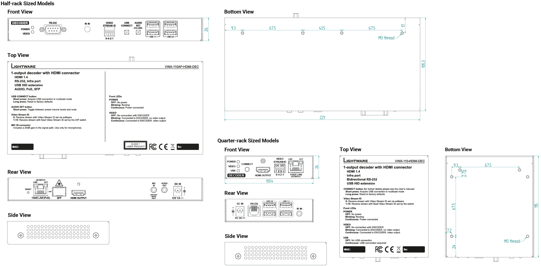
10.6. RS-232 Cable Wiring Guide
The Pinout of a DE-9 Type Serial Connector
The DE-9 type (D-subminiature, or D-sub) male or female connector is also used for RS-232 serial communication. There are two types of devices in general serial communication:
Data Terminal Equipment (DTE): This is an end instrument that converts user information into signals or reconverts received signals. Typical DTE devices: computers, LCD touch panels and control systems.
Data Circuit-terminating Equipment (DCE): This kind of device is placed between the DTE and a data transmission circuit. It is also called data communication equipment and data carrier equipment. Typical DCE devices: projectors, industrial monitors and amplifiers.
The pinout of DTE and DCE devices are different:

|
D-SUB 9 (male) and RJ12 |
D-SUB 9 (female) and RJ12 |

|

|
|
Resolution |
Frame rate |
|
640x350 |
70 |
|
640x350 |
85 |
|
640x400 |
85 |
|
640x480 |
50 |
|
640x480 |
60 |
|
640x480 |
67 |
|
640x480 |
72 |
|
640x480 |
75 |
|
640x480 |
85 |
|
720x240 |
60 |
|
720x240 |
120 |
|
720x240 |
240 |
|
720x288 |
50 |
|
720x288 |
100 |
|
720x288 |
200 |
|
720x400 |
70 |
|
720x400 |
85 |
|
720x480 (480p) |
60 |
|
720x480 |
120 |
|
720x480 |
240 |
|
720x576 (576p) |
50 |
|
720x576 |
100 |
|
720x576 |
200 |
|
768x480 |
50 |
|
768x480 |
60 |
|
768x480 |
75 |
|
768x480 |
85 |
|
800x600 |
50 |
|
800x600 |
56 |
|
800x600 |
60 |
|
800x600 |
72 |
|
800x600 |
75 |
|
800x600 |
85 |
|
832x624 |
75 |
|
834x624 |
75 |
|
848x480 |
50 |
|
848x480 |
60 |
|
848x480 |
75 |
|
848x480 |
85 |
|
852x480 |
60 |
|
960x600 |
50 |
|
960x600 |
60 |
|
960x600 |
75 |
|
960x600 |
85 |
|
1024x384 |
87 |
|
1024x576 |
60 |
|
1024x768 |
50 |
|
1024x768 |
60 |
|
1024x768 |
70 |
|
1024x768 |
75 |
|
1024x768 |
85 |
|
1064x600 |
50 |
|
1064x600 |
60 |
|
1064x600 |
75 |
|
1064x600 |
85 |
|
1152x720 |
50 |
|
1152x720 |
60 |
|
1152x720 |
75 |
|
1152x720 |
85 |
|
1152x864 |
60 |
|
1152x864 |
75 |
|
1152x864 |
85 |
|
1152x864 |
100 |
|
1152x870 |
75 |
|
1224x768 |
50 |
|
1224x768 |
60 |
|
1224x768 |
75 |
|
1224x768 |
85 |
|
1280x720 |
24 |
|
1280x720 |
25 |
|
1280x720 |
30 |
|
1280x720 (720p) |
50 |
|
1280x720 (720p) |
60 |
|
1280x720 (720p) |
75 |
|
1280x720 |
85 |
|
1280x720 |
100 |
|
1280x720 |
120 |
|
1280x768 |
50 |
|
1280x768 |
60 |
|
1280x768 |
75 |
|
1280x768 |
85 |
|
1280x800 |
60 |
|
1280x800 |
75 |
|
1280x800 |
85 |
|
1280x960 |
50 |
|
1280x960 |
60 |
|
1280x960 |
75 |
|
1280x960 |
85 |
|
1280x1024 |
50 |
|
1280x1024 |
60 |
|
1280x1024 |
75 |
|
1280x1024 |
85 |
|
1280x1024 |
96 |
|
1280x1470 |
24 |
|
1280x1470 |
30 |
|
1280x1470 |
50 |
|
1280x1470 |
60 |
|
1360x768 |
50 |
|
1360x768 |
60 |
|
1360x768 |
75 |
|
1360x768 |
85 |
|
1365x1024 |
60 |
|
1365x1024 |
75 |
|
1366x768 |
60 |
|
1400x788 |
60 |
|
1400x1050 |
50 |
|
1400x1050 |
60 |
|
1400x1050 |
75 |
|
1400x1050 |
85 |
|
1440x240 |
60 |
|
1440x288 |
50 |
|
1440x480 |
60 |
|
1440x576 |
50 |
|
1440x900 |
60 |
|
1440x900 |
75 |
|
1440x900 |
85 |
|
1440x960 |
72 |
|
1536x960 |
50 |
|
1536x960 |
60 |
|
1536x960 |
75 |
|
1536x960 |
85 |
|
1600x900 |
60 |
|
1600x1024 |
60 |
|
1600x1200 |
50 |
|
1600x1200 |
60 |
|
1600x1200 |
65 |
|
1600x1200 |
70 |
|
1600x1200 |
75 |
|
1600x1200 |
85 |
|
1600x1200 |
120 |
|
1680x1050 |
50 |
|
1680x1050 |
60 |
|
1680x1050 |
75 |
|
1680x1050 |
85 |
|
1704x960 |
50 |
|
1704x960 |
60 |
|
1704x960 |
75 |
|
1704x960 |
85 |
|
1728x1080 |
50 |
|
1728x1080 |
60 |
|
1728x1080 |
75 |
|
1728x1080 |
85 |
|
1792x1344 |
60 |
|
1792x1344 |
75 |
|
1856x1392 |
60 |
|
1856x1392 |
75 |
|
1860x1050 |
50 |
|
1860x1050 |
60 |
|
1860x1050 |
75 |
|
1860x1050 |
85 |
|
1920x540 |
50 |
|
1920x540 |
120 |
|
1920x540 |
100 |
|
1920x1080 |
24 |
|
1920x1080i |
25 |
|
1920x1080i |
29.97 |
|
1920x1080 |
30 |
|
1920x1080 (1080p) |
50 |
|
1920x1080 (1080p) |
60 |
|
1920x1080 |
75 |
|
1920x1080 |
85 |
|
1920x1200 |
50 |
|
1920x1200 |
60 |
|
1920x1200 |
75 |
|
1920x1200 |
85 |
|
1920x1440 |
50 |
|
1920x1440 |
60 |
|
1920x1440 |
75 |
|
1920x2205 |
24 |
|
1920x2205 |
30 |
|
1920x2205 |
50 |
|
1920x2205 |
60 |
|
2048x1152 |
60 |
|
2048x1280 |
60 |
|
2048x1536 |
50 |
|
2048x1536 |
60 |
|
2128x1200 |
50 |
|
2128x1200 |
60 |
|
2128x1200 |
75 |
|
2304x1440 |
50 |
|
2304x1440 |
60 |
|
2456x1536 |
50 |
|
2560x1080 |
24 |
|
2560x1080 |
25 |
|
2560x1080 |
30 |
|
2560x1080 |
50 |
|
2560x1080 |
60 |
|
2560x1200 |
30 |
|
2560x1200 |
60 |
|
2560x1440 |
50 |
|
2560x1600 |
60 |
|
2728x1536 |
50 |
|
3840x2160 |
24 |
|
3840x2160 |
25 |
|
3840x2160 |
30 |
|
2840x2160 |
50 |
|
3840x2160 |
60 |
|
4096x2160 |
24 |
|
4096x2160 |
25 |
|
4096x2160 |
30 |
|
4096x2160 |
50 |
|
4096x2160 |
60 |
|
Mem |
Resolution |
Type |
EDID features |
|||
|
F1 |
640 x |
480p |
@ 60.00 |
Hz |
D |
|
|
F3 |
800 x |
600p |
@ 60.32 |
Hz |
D |
|
|
F4 |
1024 x |
768p |
@ 60.00 |
Hz |
D |
|
|
F5 |
1280 x |
768p |
@ 50.00 |
Hz |
D |
|
|
F6 |
1280 x |
768p |
@ 59.94 |
Hz |
D |
|
|
F7 |
1280 x |
768p |
@ 75.00 |
Hz |
D |
|
|
F8 |
1360 x |
768p |
@ 60.02 |
Hz |
D |
|
|
F9 |
1280 x |
1024p |
@ 50.00 |
Hz |
D |
|
|
F10 |
1280 x |
1024p |
@ 60.02 |
Hz |
D |
|
|
F11 |
1280 x |
1024p |
@ 75.02 |
Hz |
D |
|
|
F15 |
1680 x |
1050p |
@ 60.00 |
Hz |
D |
|
|
F16 |
1920 x |
1080p |
@ 50.00 |
Hz |
D |
|
|
F17 |
1920 x |
1080p |
@ 60.00 |
Hz |
D |
|
|
F20 |
1600 x |
1200p |
@ 50.00 |
Hz |
D |
|
|
F21 |
1600 x |
1200p |
@ 60.00 |
Hz |
D |
|
|
F22 |
1920 x |
1200p |
@ 50.00 |
Hz |
D |
|
|
F23 |
1920 x |
1200p |
@ 59.56 |
Hz |
D |
|
|
F29 |
1920 x |
1080p |
@ 60.00 |
Hz |
U |
|
|
F32 |
640 x |
480p |
@ 59.95 |
Hz |
H |
2chLPCM |
|
F33 |
720 x |
480p |
@ 59.94 |
Hz |
H |
2chLPCM |
|
F34 |
720 x |
576p |
@ 50.00 |
Hz |
H |
2chLPCM |
|
F35 |
1280 x |
720p |
@ 50.00 |
Hz |
H |
2chLPCM |
|
F36 |
1280 x |
720p |
@ 60.00 |
Hz |
H |
2chLPCM |
|
F37 |
1920 x |
1080i |
@ 50.04 |
Hz |
H |
2chLPCM |
|
F38 |
1920 x |
1080i |
@ 50.00 |
Hz |
H |
2chLPCM |
|
F39 |
1920 x |
1080i |
@ 60.05 |
Hz |
H |
2chLPCM |
|
F40 |
1920 x |
1080i |
@ 60.05 |
Hz |
H |
2chLPCM |
|
F41 |
1920 x |
1080p |
@ 24.00 |
Hz |
H |
2chLPCM |
|
F42 |
1920 x |
1080p |
@ 25.00 |
Hz |
H |
2chLPCM |
|
F43 |
1920 x |
1080p |
@ 30.00 |
Hz |
H |
2chLPCM |
|
F44 |
1920 x |
1080p |
@ 50.00 |
Hz |
H |
2chLPCM |
|
F45 |
1920 x |
1080p |
@ 59.94 |
Hz |
H |
2chLPCM |
|
F46 |
1920 x |
1080p |
@ 60.00 |
Hz |
H |
2chLPCM |
|
F47 |
1920 x |
1080p |
@ 60.00 |
Hz |
U |
2chLPCM |
|
F48 |
1920 x |
1080p |
@ 60.00 |
Hz |
U |
2chLPCM, 8chLPCM, DD, DTS, AAC, DD+, DTS-HD, MLP, DST, WMAP |
|
F49 |
1920 x |
1080p |
@ 60.00 |
Hz |
U |
2chLPCM, 8chLPCM, DD, DTS, AAC, DD+, DTS-HD, MLP, DST, WMAP |
|
F50 |
720 x |
480i |
@ 30.03 |
Hz |
A |
|
|
F51 |
720 x |
576i |
@ 25.04 |
Hz |
A |
|
|
F52 |
640 x |
480p |
@ 60.00 |
Hz |
A |
|
|
F53 |
640 x |
480p |
@ 75.00 |
Hz |
A |
|
|
F54 |
800 x |
600p |
@ 50.00 |
Hz |
A |
|
|
F55 |
800 x |
600p |
@ 60.32 |
Hz |
A |
|
|
F56 |
800 x |
600p |
@ 75.00 |
Hz |
A |
|
|
F57 |
1024 x |
768p |
@ 49.99 |
Hz |
A |
|
|
F58 |
1024 x |
768p |
@ 60.00 |
Hz |
A |
|
|
F59 |
1024 x |
768p |
@ 75.03 |
Hz |
A |
|
|
F60 |
1280 x |
768p |
@ 50.00 |
Hz |
A |
|
|
F61 |
1280 x |
768p |
@ 59.94 |
Hz |
A |
|
|
F62 |
1280 x |
768p |
@ 75.00 |
Hz |
A |
|
|
F63 |
1360 x |
768p |
@ 60.02 |
Hz |
A |
|
|
F64 |
1364 x |
768p |
@ 50.00 |
Hz |
A |
|
|
F65 |
1364 x |
768p |
@ 59.94 |
Hz |
A |
|
|
F66 |
1364 x |
768p |
@ 74.99 |
Hz |
A |
|
|
F67 |
1280 x |
1024p |
@ 50.00 |
Hz |
A |
|
|
F68 |
1280 x |
1024p |
@ 60.02 |
Hz |
A |
|
|
F69 |
1366 x |
1024p |
@ 60.00 |
Hz |
A |
|
|
F70 |
1400 x |
1050p |
@ 50.00 |
Hz |
A |
|
|
F71 |
1400 x |
1050p |
@ 60.00 |
Hz |
A |
|
|
F72 |
1400 x |
1050p |
@ 75.00 |
Hz |
A |
|
|
F73 |
1920 x |
540i |
@ 50.00 |
Hz |
A |
|
|
F74 |
1920 x |
540i |
@ 60.00 |
Hz |
A |
|
|
F75 |
1920 x |
1080p |
@ 50.00 |
Hz |
A |
|
|
F76 |
1920 x |
1080p |
@ 60.00 |
Hz |
A |
|
|
F89 |
1920 x |
1200p |
@ 59.56 |
Hz |
U |
|
|
F96 |
2560 x |
1600p |
@ 59.86 |
Hz |
D |
|
|
F100 |
1024 x |
768p |
@ 60.00 |
Hz |
H |
2chLPCM |
|
F101 |
1280 x |
1024p |
@ 50.00 |
Hz |
H |
2chLPCM |
|
F102 |
1280 x |
1024p |
@ 60.02 |
Hz |
H |
2chLPCM |
|
F103 |
1280 x |
1024p |
@ 75.02 |
Hz |
H |
2chLPCM |
|
F104 |
1600 x |
1200p |
@ 50.00 |
Hz |
H |
2chLPCM |
|
F105 |
1600 x |
1200p |
@ 60.00 |
Hz |
H |
2chLPCM |
|
F106 |
1920 x |
1200p |
@ 59.56 |
Hz |
H |
2chLPCM |
|
F108 |
2560 x |
1600p |
@ 59.86 |
Hz |
H |
2chLPCM |
|
F110 |
3840 x |
2160p |
@ 24.00 |
Hz |
H |
2chLPCM |
|
F111 |
3840 x |
2160p |
@ 25.00 |
Hz |
H |
2chLPCM |
|
F112 |
3840 x |
2160p |
@ 30.00 |
Hz |
H |
2chLPCM |
|
F118 |
3840 x |
2160p |
@ 30.00 |
Hz |
U |
2chLPCM |
|
F119 |
3840 x |
2160p |
@ 30.00 |
Hz |
U |
2chLPCM, 8chLPCM, DD, DTS, AAC, DD+, DTS-HD, MLP, DST, WMAP |
|
F125 |
1366 x |
768p |
@ 60.00 |
Hz |
H |
2chLPCM |
|
F131 |
4096 x |
2160p |
@ 25.00 |
Hz |
H |
2chLPCM |
|
F132 |
4096 x |
2160p |
@ 30.00 |
Hz |
H |
2chLPCM |
Legend
D: DVI EDID
H: HDMI EDID
U: Universal EDID, supporting many standard resolutions:
▪F29: Universal EDID for DVI signals (no audio support).
▪F47: HDMI EDID supporting PCM audio.
▪F48: HDMI EDID supporting all type of audio.
▪F49: HDMI EDID supporting all type of audio and deep color.
▪F89: Universal EDID for analog signals (no audio support).
▪F118: HDMI EDID supporting PCM audio and 4K@30 Hz signals.
▪F119: HDMI EDID supporting all type of audio and 4K@30 Hz signals.
The list below shows the released firmware packages with important notes.
v3.2.5b3
Release date: 2023-08-21
New feature:
▪Fixed HDCP issue for AP encoder with HDCP 2.2 sources.
Bugfix:
▪Fixed the audio bug that appeared in the revoked v3.2.4 firmware. Removed the "Enable HDCP on HDMI" checkbox, because it belonged to a non-working feature and firmware v3.2.5 does not accept the previous LW3 command.
v3.2.4b3
Release date: 2023-08-01
New feature:
▪Fixed HDCP issue for AP encoder with HDCP 2.2 sources.
v3.2.2b3
Release date: 2023-05-12
New feature:
▪Added the custom hostname setting function on VINX devices with firmware v3.2.2
v3.1.1b4
Release date: 2022-05-04
New feature:
▪From this version on, the value of Video stream ID can be as high as 9999. Consequently, the number of encoders in the system can be 9999.
▪From this version on, login to the VINX devices can be made password protected.
▪Improved the update process.
Bugfix:
▪Fixed a bug that caused the VINX splash screen to be overlaid over the video content on the decoder output.
▪Fixed a bug that resulted in a video wall pictogram with the wrong video wall size in the Properties pane of the Crosspoint view.
▪Fixed a bug that caused a change in the Video stream ID on the decoder not to be executed when the encoder was restarted or the connection to the encoder was temporarily lost for some other reason.
▪Fixed a bug that caused the crosspoint not to be rendered correctly if there was a video wall defined somewhere in the subnet.
▪Fixed a bug that prevented the Frame detector data from being copied from the embedded web.
Known issue:
▪When using Apple TV 4k or other Apple product as a video source with the VINX-120AP-HDMI-ENC, VINX_210AP-HDMI-ENC or VINX- 120AP-HDMI-ENC-DNT encoder, the HDCP handshake might not be successful and no video would be transmitted unless a DVI EDID (e.g. from the factory EDIDs) is emulated first towards the video source. After emulation of the DVI EDID, any new EDID emulated towards the video source will result in successful HDCP handshake and proper video transmission until the Apple TV 4k device is restarted.
▪It might happen that the VINX splash screen is briefly shown on the output of the decoder when a previously broken link to the corresponding encoder is restored.
v3.0.1b8
Release date: 2021-12-10
New feature:
▪From this version on, the limit on the number of devices supported in the crosspoint view is lifted. Thus, the crosspoint view can display all devices in the subnet.
▪From this version on, three custom images can be uploaded on the VINX decoders. These images can be used as company logos whenever the connection to the encoder is lost or there is no video from the encoder.
▪From this version on, the WP-VINX-110P-HDMI-ENC (VINX wallplate version) is also supported.
▪From this version on, the crosspoint has a tile view of the inputs and outputs with the respective preview images displayed on the tiles.
Known issue:
▪If the DIP switch is disabled by setting the 'DipSwitchEnable' property to false and the DIP switch setting is other than '0000', the Video Stream Id cannot be set from software through LW3 or the graphical user interface.
▪It might take an unusually long time to display the crosspoint view when there are more than 100 VINX devices in the subnet.
▪The Frame detector data cannot be copied from the embedded web. The same data can be copied from LDC, though.
▪It might happen that the VINX splash screen is overlaid over the company logo.
▪The extension of the image file to be uploaded as company logo is case sensitive. Use lower case extension to avoid the problem.
▪The available space for storing company logos is erroneously reported as 0 (under StorageFreeSize) if no image file for company logo is uploaded.
v2.0.2b4
Release date: 2021-01-12
New feature:
▪From this version on, black screen or the VINX screen can be selected to display when there is no video signal in the decoder.
v2.0.1b3
Release date: 2020-02-19
Bugfix:
▪Fixed a bug that caused popping sound on analog audio output when changing streams
Known issue:
▪On a VINX-110AP-HDMI-DEC, when both USB 2.0 ports are used, the analog audio signal on the output might be jammed during stream change
v2.0.0b27
Release date: 2020-01-16
New feature:
▪Factory defaults button added to Advanced Setup page.
▪From this version on, the firmware supports the VINX-120AP-HDMI-ENC-DNT encoder.
▪From this version on, the device can be set to use static IP address, use dynamic IP address either with or without falling back to AutoIP, or continue with dynamic IP address query even after AutoIP was set.
▪From this version on, the HPD signal on the HDMI input of an encoder can be toggled.
▪Improved switching time considerably. (Switching time is the time elapsed between switching to another source and providing a stable output on the output HDMI port.)
Bugfix:
▪Fixed a bug that resulted in some LW3 requests not to be executed when the sender closed the TCP connection before receiving an answer for the request from the VINX device.
v1.4.1b2
Release date: 2019-07-03
Bugfix:
▪Fixed a bug that caused the IP related settings to be restored to their factory default values (to DHCP) when upgrading to v1.4.0.
v1.4.0b7
Release date: 2019-07-05
New feature:
▪Added support for VINX-210AP-HDMI-ENC, VINX-120AP-HDMI-ENC, and VINX-110AP-HDMI-DEC.
▪From this version on, the exact product name is presented to the user in the header of the built-in web and in LDC.
▪From this version on, both the encoder and the decoder can be set whether or not to use jumbo frames. Note, that this setting is only available from LW3 and the decoder and the corresponding encoder shall be set to the same setting.
Bugfix:
▪Fixed a bug that might have resulted in the Advanced Settings page to be rendered incorrectly at some resolutions.
Known issue:
▪Pressing the front panel key (COMP MODE or USB CONNECT) for less than ten seconds might reset the device to its factory settings.
▪On a VINX-120-HDMI-ENC device, The EDID is not read from the sink connected to the local output of the encoder. Thus, it cannot be used as a dynamic EDID.
▪Some parameters of the EDID emulated on the HDMI input of VINX-210AP-HDMI-ENC and VINX-120AP-HDMI-ENC (other than the preferred timing) might get modified.
▪VINX-210AP-HDMI-ENC might indicate wrong resolution for incoming analog signals with frame rate of 50 Hz.
▪On a VINX-110AP-HDMI-DEC, compressed audio might be output for a brief period of time which results in digital noise on the output.
v1.3.0b5
Release date: 2018-12-18
New feature:
▪Added controls for setting the RS-232 mode to Pass-through or Command injection.
▪Added a Crosspoint tab to the graphical user interface. In the crosspoint tab it is possible to route any input to any output as long as the number of encoders and decoders in the subnet does not exceed 24 and the number of encoders is less or equal to 16.
Bugfix:
▪Fixed a bug that caused the firmware upgrade to stop at 20% when upgrading through LDU2.
▪Fixed a bug that caused the Output scaling radio button group to work hectically when the Output standard is set to DVI.
v1.2.1b1
Release date: 2018-10-24
Bugfix:
▪Fixed a bug that resulted in wrong output format for scaling set to 1920x1080@50Hz.
v1.2.0b9
Release date: 2018-10-18
New feature:
▪From this version on, the video mode related settings (Video quality as referred to in earlier versions) have been given a more descriptive and self explaining name.
▪The Connect button in the Main Settings page has been renamed to Open Device.
▪From this version on VINX devices are supported by the Lightware Device Manager.
▪From this version on, the graphical user interface displays a preview image of the encoder input.
▪Improved response time of the devices. As a result, changes made to the devices are reflected faster on the graphical user interface.
▪The list of available output formats has been consolidated and a few output formats have been added.
▪From this version on, the name of the device appears on the tab of the Programmers' LW3 Terminal window.
Bugfix:
▪Fixed a bug that caused the video not to be transmitted properly in Unicast mode when switching Video Stream ID on the encoder.
▪Fixed a bug that caused the Auto detect from EDID scaler feature not to work properly after a factory reset.
▪Fixed a bug that caused the device to switch to Unicast mode from Multicast mode only at the second click on the corresponding button on the Advanced Settings page.
▪Fixed a bug that let the user select two decoders to receive the same video stream in Unicast mode.
▪Fixed a bug that caused the connection to the device to be lost when changing Video Stream ID on the decoder multiple times in rapid succession.
▪Fixed a bug that caused the USB LED on the decoder not to reflect valid information when pressing the Connect button on several decoders connected to the same encoder in rapid successions multiple times.
▪Added a warning message to state that the device having an Auto IP of 169.254.x.x cannot be detected after firmware upgrade as the IP address will change after a reboot.
▪Fixed a bug that caused the Delete video wall button on the Video Wall Setup page to be active even if there is no video wall selected.
▪Fixed a bug that let the user enter invalid value for stop bit in the LW3 tree view.
▪Fixed a bug that caused the IGMP packets to be disregarded by certain switches due to missing Router Alert option from the IP header. Thus, it is no longer necessary to disable IP header validation on the switches.
▪Fixed a bug that caused connection reset during firmware upgrade by LDU2.
▪Fixed a bug that caused the Programmers' LW3 Terminal window to be rendered incorrectly at certain resolutions.
Known issue:
▪The video wall being edited can lose focus when it is saved.
▪The Output scaling radio button group works hectically when the Output standard is set to DVI.
v1.1.1b2
Release date: 2018-06-07
Bugfix:
▪Fixed a bug that degraded switching speed.
v1.1.0b7
Release date: 2018-05-31
New feature:
▪From this version on, the items in the Emulated EDID on input list reflect the monitor name field of the EDID instead of the format parameters for better identification.
▪New EDIDs have been added to the factory EDID list.
▪From this version on, the OSD messages that appear on the display connected to the VINX decoder are turned off by default. They can be turned on individually or globally, though.
▪From this version on, information like the IP address of a decoder and the position within a video wall can be temporarily displayed on the monitor attached to a VINX decoder. This will ease the setup of video walls.
▪For smooth video playback, the default operation mode has been changed from Graphic Mode to Video Mode.
▪From this version on, VINX encoder and decoder units can be upgraded in batches by LDU2.
▪It is now possible to disable (by an LW3 property) the DIP switch setting of the video stream ID.
▪Version number of several components including package version has been added to the graphical user interface.
▪It is now possible to set bandwidth limit for the encoded video stream generated by the encoder.
▪It is now possible to create a list of favourite channels and associate shortcut keys to cycle through the list up and down. Moreover, shortcut keys can be associated with specific streams. The associated shortcut key, when pressed on a keyboard attached to a decoder, can be used to trigger the corrsponding action.
▪It is now possible to connect to an encoder from a decoder or to a decoder from an encoder by clicking on a Connect button in the list of available devices on the Main Settings page.
Bugfix:
▪Fixed a bug that caused VINX-HDMI-120-ENC and VINX-HDMI-110-DEC not to be accessible via http://lwr-gatewayAABBCCDDEEFF.local or http://lwr-clientAABBCCDDEEFF.local, respectively, where AABBCCDDEEFF is the MAC address without colons of the device to be accessed.
▪Fixed a bug that caused a decoder device to display invalid content when it was removed from a video wall.
▪Fixed a bug that casued the VINX encoder to restart when the corresponding decoder was reading an EDID from the attached device that had a Video Format Preference block in its CEA extension.
▪Fixed a bug that caused the RS-232 symbol rate not to be displayed correctly when a custom value was set via LW3.
Known issue:
▪When defining a shortcut key combination for switching to previous or next stream or for a stream shortcut, and the shortcut key combination has more modifier keys, the box containing the key combination might get truncated.
▪When an encoder is switched to Unicast mode and restarted, it still can receive the USB stream coming from a decoder in Multicast mode and having the same Video Stream ID.
▪The Programmers' LW3 Terminal window might get rendered incorrectly at certain resolutions.
▪When dragged at certain pixel positions it is impossible to move an item from the tile representing a video wall element on the Video Wall Setup page.
▪Switching source or destination through the Device list pane on the Main Settings page of the encoder or decoder might take more time compared to switching directly by modifying the ID in the Video stream ID box.
v1.0.0b11
Release date: 2017-12-14
Known issue:
▪The same Video Stream ID can be set on multiple VINX-120-HDMI-ENC devices that results in an UDP packet collision and erroneous video transmission.
▪Neither VINX-HDMI-120-ENC, nor VINX-HDMI-110-DEC can be accessed via http://lwr-gatewayAABBCCDDEEFF.local or http://lwr-clientAABBCCDDEEFF.local, respectively, where AABBCCDDEEFF is the MAC address without colons of the device to be accessed.
▪EDID information cannot be read by the source attached to the HDMI input of a VINX-120-HDMI-ENC device if HDCP is disabled on the input.
▪Only 225.0.1.x can be selected as a multicast base address.
▪Although changing parameters usually takes effect within an acceptable period of time, it might happen that feedback is not received for up to several seconds. This can result in uncertainty on the graphical user interface. This is the reason why e.g. a video wall seemingly still exists although it has already been deleted.
10.10. Application Note (LW-AN-001)
Gigabit Network Switch Requirements For VINX Devices
Network Properties
Network-based AV products use different network protocols for different operations. The network protocol can be UDP/IP and TCP/IP, the transmission mode can be Broadcast, Unicast, and Multicast.
These network protocols should be familiar to any network engineer. Because our network-based AV solutions bridge the gap between the audio-visual (AV) and information technology (IT) worlds, Lightware suggests involvement of both AV and IT departments in any installation.
Lightware products are designed to be plug-and-play. The figures in the next section illustrate the basic installation of one Decoder and one Encoder. A video source provides the digital video content to the Encoder which converts it to Ethernet packets and sends it to the attached Decoder. The Decoder reconstitutes the video with synchronized audio for presentation to the attached display.
Point-to-point vs Network Connection
VINX Encoders and Decoders have two typical applications:
▪Point-to-point connection
▪Point-to-multi point connection
Point-to-point Connection (Unicast mode)
Unicast transmission mode uses a one-to-one association between the source and the destination: each destination address uniquely identifies a single Decoder endpoint.

Point-to-Multi Point Connection (Multicast mode)
Multicast transmission mode uses a one-to-one or one-to-many association; multicast datagrams are forwarded simultaneously in a single transmission to many recipients through L2 swithed network. There can be multiple encoders in a L2 subnet. The decoders have to be in the same subnet.

Unicast Routing
The packet forwarding requirement of the VINX devices for point-to-point connection is the unicast switching. Please note that the unicast mode is not the default setting of the Encoder and Decoder, users have to set it in the devices.

Hardware Requirement:
▪1 GbE Layer 2 (L2) switch
ATTENTION!VINX devices send certain system commands over multicast packages. If the multicast packet forwarding is disabled on the network, the signal transmission can fail.
Managed Switch for Multicast Routing
In TCP/IP terminology, Layer 2 is the data link layer that is responsible for splitting the information coming from higher layers in the TCP/ IP stack into Ethernet frames. An Ethernet frame includes, among others, labeling information with source and destination physical addresses (called source and destination MAC address). These physical addresses uniquely identify the source and destination physical devices (e.g. a VINX Encoder and a VINX Decoder). Ethernet frames provide error resilience by incorporating a redundancy check field, through which transmission errors can easily be detected. The device that uses only the physical address information found in the Ethernet frame to forward a packet from one of its input ports to one or more of its output ports is an unmanaged switch.
A managed switch, on the other hand, can handle the traffic and forward input packets to output packets by utilizing information from higher layers. This gives the managed switch more flexibility and also allows for more sophisticated functions like multicast forwarding. Since even a simple VINX network, where one VINX Encoder supplies more VINX Decoders, relies on multicasting, a multicast capable switch (i.e. a managed one) is mandatory. If non-managed switches transmit the multicast packages, the multicast traffic is usually broadcasted over all interfaces.

Hardware Requirement:
▪1 GbE Layer 3 (L3) switch or managed L2 switch
Why is it important?
By default, Lightware Video-over-IP Encoders and Decoders use multicast packet forwarding. The switches in the network shall offer the following capabilities:
▪IGMPv2
▪IGMP snooping
▪IGMP fast leave
▪IGMP Querier
▪Multicast filtering
▪9k MTU - Jumbo/Giant frames
Switch Setup for Dante® Audio Signal Transmission
You can configure the QoS settings to ensure good system performance in a busy network. QoS (Quality of Service) refers to technology for prioritizing the transfer of specific data. By configuring the QoS settings recommended by Dante® on a network switch, you can prioritize the transfer of Dante® clock synchronization data and audio data over background data traffic. This will ensure good system performance when you need to transfer non-Dante® data over the same network. QoS is required when using Dante in networks that have 100Mbps devices, and is optional in networks with Gigabit devices. We recommend that QoS be enabled in all Dante® networks in order to ensure proper operation under all possible conditions.
The table below shows how Dante uses various Diffserv Code Points (DSCP) packet priority values: *
|
Priority |
Usage |
DSCP Label |
Hex |
Decimal |
Binary |
|
High |
Time critical PTP events |
CS7 |
0x38 |
56 |
111000 |
|
Medium |
Audio, PTP |
EF |
0x2E |
46 |
101110 |
|
Low |
(reserved) |
CS1 |
0x08 |
8 |
001000 |
|
None |
Other traffic |
BestEffort |
0x00 |
0 |
000000 |
* source: https://www.audinate.com/learning/faqs
Green Ethernet in the Network
EEE (Energy Efficient Ethernet) is a technology that reduces switch power consumption during periods of low network traffic. It is also sometimes known as Green Ethernet and IEEE802.3az.
Although power management should be negotiated automatically in switches that support EEE, it is a relatively new technology, and some switches do not perform the negotiation properly. This may cause EEE to be enabled in Dante networks when it is not appropriate, resulting in poor synchronisation performance and occasional dropouts.
Managed Switch Properties in Details
IGMPv2
IGMPv2 is version 2 of the Internet Group Management Protocol. This protocol is used by end-point devices to signal their interest in receiving a specific multicast content via subscribing to the multicast group corresponding to the content. Using IGMPv2 packets, the end-point devices can send a leave message to indicate that they are no longer interested in receiving the stream of the multicast group. Moreover, a multicast capable router can periodically poll the end-point devices on its interfaces which multicast streams they are interested to receive. The answer to such a query is called a membership report. IGMPv2 must be supported by the managed switch.
IGMP Snooping
IGMP snooping is a feature which allows the switch to monitor IGMP traffic when enabled. The information collected from the IGMP packets is used by the managed switch to determine which interfaces the multicast traffic should be forwarded to. In other words, IGMP snooping is used to conserve bandwidth by allowing the switch to forward multicast traffic to those interfaces where it is really required.
IGMP Fast Leave
IGMP fast leave (or immediate leave), when configured, reduces the amount of time it takes for the managed switch to stop sending multicast traffic (corresponding to a multicast group defined by a multicast address) to an interface, where all end-point devices that used to be interested in a stream have sent a IGMP leave message. Without fast leave being enabled, the managed switch would first send out a query message and then would stop forwarding when no end-points answered within a pre-specified time interval. If fast leave is enabled, the switch stops forwarding the traffic without sending a query message.
IGMP Querier
In order for IGMP snooping to work properly, IGMP messages must traverse in the subnet between managed switches. However, if there is no multicast capable router present, periodically sending out query messages and receiving answers to those queries, IGMP messages are usually not forwarded upstream from one switch to another. By enabling the IGMP querier feature in a managed switch, the managed switch will act like a router, and will periodically query the devices in the subnet (even other managed switches) to send their membership reports. From those reports, all the listening switches with IGMP snooping enabled will be able to determine where multicast traffic should be sent to.
Multicast Filtering
Some control information from VINX devices is transmitted via multicast packets. However, these packets are not registered during certain startup intervals, or not registered at all. In order for all VINX devices in the subnet to receive such control information, multicast filtering must be set up, so that unregistered groups are forwarded to all interfaces on the managed switch.
Jumbo/Giant Frames
Ethernet frames consist of a header and a payload. Since the header has a fixed length (20 or 26 bytes), the bigger the payload, the higher the useful bandwidth is. Similarly, the higher the useful bandwidth, the better the picture quality of the encoded video stream will be. To maximize picture quality, the Ethernet frame size (and consequently, the payload) should be as high as possible. In a normal Ethernet frame, the payload can be at most 1500 bytes. An Ethernet jumbo frame, however, can carry up to 9000 bytes of payload. Since the goal of the transmission is to provide the best possible picture quality in all circumstances, the VINX Encoder device produces Ethernet jumbo frames. Thus, the handling of jumbo frames has to be enabled in the managed switches.
This user's manual contains keywords with hashtag (#) to help you find the relevant information as quick as possible.
The format of the keywords is the following:
#<keyword>
The usage of the keywords: use the Search function (Ctrl+F / Cmd+F) of your PDF reader application, type the # (hashtag) character and the wished keyword.
The #new special keyword indicates a new feature/function that has just appeared in the latest firmware or software version.
Example
#dhcp
This keyword is placed at the DHCP (dynamic IP address) setting in the front panel operation, the Lightware Device Controller (LDC) and the LW3 programmer's reference section.
The following list contains all hashtag keywords placed in the document with a short description belonging to them. The list is in alphabetical order by the hashtag keywords.
|
Hashtag keyword |
Description |
|
#advancedview |
Advanced view window |
|
#analogaudio |
Analog audio related settings |
|
#audio |
Audio related settings |
|
#bandwidth |
Video stream bandwidth settings |
|
#button |
Description of the front panel buttons |
|
#compression |
Video compression settings |
|
#crosspoint |
Crosspoint switch setting |
|
#dante |
Dante® audio related settings |
|
#devicelabel |
Device label |
|
#dhcp |
Dynamic IP address (DHCP) setting |
|
#dipswitch |
Description of the front panel DIP switches |
|
#edid |
EDID related settings |
|
#factory |
Factory default settings |
|
#firmwareversion |
Firmware version query |
|
#flip |
Picture rotation/flip setting |
|
#framedetector |
Frame detector in LDC/built-in web |
|
#hdcp |
HDCP-encryption related setting |
|
#inputselection |
Video input selection for VINX-210AP-HDMI-ENC model |
|
#ipaddress |
IP address related settings |
|
#kvm |
USB KVM related settings |
|
#label |
Device label |
|
#led |
Description of the front panel LEDs |
|
#login |
Cleartext login feature |
|
#multicast |
Multicast mode setting |
|
#mute |
Mute/unmute (for analog audio) setting |
|
#network |
Network (IP address) related settings |
|
#new |
New feature/function of the product |
|
#osd |
OSD settings |
|
#qualitymode |
Video quality mode setting |
|
#reboot |
Restarting the device |
|
#reset |
Restarting the device |
|
#resolution |
Resolution of the video signal query |
|
#restart |
Restarting the device |
|
#rotation |
Picture rotation/flip setting |
|
#rs232 |
RS-232 related settings |
|
#rs-232 |
RS-232 related settings |
|
#scaler |
Scaler related settings |
|
#serial |
RS-232 related settings |
|
#signaltype |
Signal type (HDMI/DVI) setting |
|
#source |
Video source selection |
|
#status |
Status query |
|
#streamid |
Video Stream ID settings |
|
#switch |
Crosspoint switch setting |
|
#terminal |
Advanced view window |
|
#unicast |
Unicast mode setting |
|
#unmute |
Mute/unmute (for analog audio) setting |
|
#usbkvm |
USB KVM related settings |
|
#videoquality |
Video quality mode setting |
|
#videostreamid |
Video Stream ID settings |
|
#videowall |
Videowall related settings |
|
#volume |
Volume (for analog audio) setting |
10.12. Applied Ports (Network Settings)
The following ports are necessary to pass via a network switch/firewall for a proper working between the device and the softwares:
|
Purpose/function |
Affected software |
Protocol |
Port nr. |
|
Firmware update TFTP |
LDU2 |
UDP |
69 |
|
UDP |
49990 |
||
|
UDP |
49995 |
||
|
Device Discovery |
LDC |
UDP |
224.0.0.251:5353 |
|
Remote IP |
LDC |
UDP |
230.76.87.82:37421 |
|
LW3 protocol |
- |
TCP |
6107 |
|
HTTP port |
- |
TCP |
80 |
|
RS-232 command injection |
- |
TCP |
6752 |
VINX-210AP-HDMI-ENC
|
Video port |
Audio port |
|
|
HDMI in |
I1 |
I1 |
|
VGA in |
I2 |
- |
|
Analog in |
- |
I2 |
|
Analog out |
- |
O1 |
VINX-120AP-HDMI-ENC and VINX-120AP-HDMI-ENC-DNT
|
Video port |
Audio port |
|
|
HDMI in |
I1 |
I1 |
|
Analog in |
- |
I2 |
|
Analog out |
- |
O1 |
VINX-110AP-HDMI-DEC
|
Video port |
Audio port |
|
|
HDMI out |
O1 |
O1 |
|
Microphone in |
- |
I2 |
|
Analog out |
- |
O2 |
10.14. Further Information
Limited Warranty Statement
1. Lightware Visual Engineering PLC (Lightware) warrants to all trade and end user customers that any Lightware product purchased will be free from manufacturing defects in both material and workmanship for three (3) years from purchase unless stated otherwise below. The warranty period will begin on the latest possible date where proof of purchase/delivery can be provided by the customer. In the event that no proof can be provided (empty ‘Date of purchase’ field or a copy of invoice), the warranty period will begin from the point of delivery from Lightware.
1.1. 25G and MODEX product series will be subject to a seven (7) year warranty period under the same terms as outlined in this document.
1.2. If during the first three (3) months of purchase, the customer is unhappy with any aspect of a Lightware product, Lightware will accept a return for full credit.
1.3. Any product that fails in the first six (6) months of the warranty period will automatically be eligible for replacement and advanced replacement where available. Any replacements provided will be warranted for the remainder of the original unit’s warranty period.
1.4. Product failures from six (6) months to the end of the warranty period will either be repaired or replaced at the discretion of Lightware. If Lightware chooses to replace the product, then the replacement will be warranted for the remainder of the original unit’s warranty period.
2. The above-stated warranty and procedures will not apply to any product that has been:
2.1. Modified, repaired or altered by anyone other than a certified Lightware engineer unless expressly agreed beforehand.
2.2. Used in any application other than that for which it was intended.
2.3. Subjected to any mechanical or electrical abuse or accidental damage.
2.4. Any costs incurred for repair/replacement of goods that fall into the above categories (2.1., 2.2., 2.3.) will be borne by the customer at a pre-agreed figure.
3. All products to be returned to Lightware require a return material authorization number (RMA) prior to shipment, and this number must be clearly marked on the box. If an RMA number is not obtained or is not clearly marked on the box, Lightware will refuse the shipment.
3.1. The customer will be responsible for in-bound and Lightware will be responsible for out-bound shipping costs.
3.2. Newly repaired or replaced products will be warranted to the end of the originally purchased product's warranty period.
Document Revision History
|
Rev. |
Release date |
Changes |
Editor |
|
1.0 |
21-12-2017 |
Initial release. |
Laszlo Zsedenyi |
|
. . . |
|||
|
2.11 |
26-05-2023 |
Host name setting function added, minor corrections |
Nikolett Keindl |
|
2.12 |
12-12-2023 |
Specifications updated |
Tamas Forgacs |
Contact Us
+36 1 255 3800
+36 1 255 3810
Lightware Visual Engineering PLC.
Peterdy 15, Budapest H-1071, Hungary
©2024 Lightware Visual Engineering. All rights reserved. All trademarks mentioned are the property of their respective owners. Specifications subject to change without notice.