Thank you for choosing Lightware’s Room Automation Panel series device. In the first chapter we would like to introduce the device, highlighting the most important features in the coming sections.
1.1. Description
Room Automation Panel is an integrated control solution for AV systems installed in collaborative spaces. It features a programmable keypad, a volume knob, and a processor running Lightware Event Manager.
The stylish unit is available in different sizes and colors which fit EU, US and UK electrical boxes and tabletop enclosures. Rear panel RS-232, 3xGPIO and 2xRJ-45 ports provide connection to controlled devices. Snap-on front cover and PoE receiver of the first RJ-45 connector make the installation smooth. The additional RJ-45 connector makes cabling flexible and can supply PoE when an AC adapter is plugged in.
Model Denomination

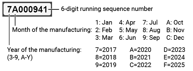
Lightware devices contain a label indicating the unique serial number of the product. The structure is the following:
1.2. Model Comparison
1.2.1. Comparison of RAP and RAC Models
|
RAP-B511 series |
RAC-B501 |
|
|
User interface |
11 configurable buttons & jog dial control knob |
1 configurable button & 1 configurable feedback LED |
|
Wall mountable |
|
|
|
Rack mountable |
|
|
|
Recommended application |
Auditorium; Conference rooms, Office meeting rooms; Operation centers, Residential |
Fixed install venue; Live events, Office meeting rooms |


1.2.2. Comparison of RAP-B511 Series Models
INFO:All models have the same look and functionality, the difference is the size and color of the enclosure.
|
Model name |
Color |
Outlet box type |
|
|
RAP-B511-EU-K |

|
black |
Double EU wall box (65mm) |
|
RAP-B511-EU-W |

|
white |
|
|
RAP-B511-EU-S |

|
brushed steel |
|
|
RAP-B511-UK-K |

|
black |
Double UK wall box |
|
RAP-B511-UK-W |

|
white |
|
|
RAP-B511-UK-S |

|
brushed steel |
|
|
RAP-B511-US-K |
|
black |
Double US wall box |
|
RAP-B511-US-W |
|
white |
|
|
RAP-B511-US-S |
|
brushed steel |
|
1.3. Compatible Devices
Room automation panel has standard RS-232, Ethernet and GPIO ports which are compatible with other Lightware products or third-party devices which have the same signal type.
1.4. Box Contents
1.4.1. Supplied Accessories
The following table describes all supplied accessories of the Room Automation Devices by models
|
Supplied devices |
Supplied accessories |
||||||

|

|

|

|

|

|

|
|
|
RAP-B511 series device |
RAC-B501 device |
Safety and warranty info; QSG |
Phoenix® Combicon 3-pole connector |
Phoenix® Combicon 4-pole connector |
Labels for button caps |
Transparent button caps in a plastic bag * |
|
|
RAP-B511-EU-K |
|
|
|
|
|
|
|
|
RAP-B511-EU-W |
|
|
|
|
|
|
|
|
RAP-B511-EU-S |
|
|
|
|
|
|
|
|
RAP-B511-UK-K |
|
|
|
|
|
|
|
|
RAP-B511-UK-W |
|
|
|
|
|
|
|
|
RAP-B511-UK-S |
|
|
|
|
|
|
|
|
RAP-B511-US-K |
|
|
|
|
|
|
|
|
RAP-B511-US-W |
|
|
|
|
|
|
|
|
RAP-B511-US-S |
|
|
|
|
|
|
|
|
RAC-B501 #new |
|
|
|
|
|
|
|


* The transparent caps are not placed onto the buttons, thus, you can easily insert the desired labels and fix the caps – see the Label and Cap Fixation section.
1.4.2. Optional Accessories
The following table describes all supplied and optional accessories of the Room Automation Devices by models. The optional (not-supplied) accessories can be purchased separately; please contact sales@lightware.com.
|
Optional accessories |
|||||||
.png)
|
.png)
|

|

|

|

|

|
|
|
48V DC adaptor with 2-pole Phoenix® plug |
USB cable (mini-B - USB-A) |
1U high rack shelf |
UD Mounting Plate F110 |
UD Mounting Plate F120 |
UD Mounting Pro P110 |
UD Mounting Pro P140 |
|
|
RAP-B511-EU-K |
|
|
- |
- |
- |
- |
- |
|
RAP-B511-EU-W |
|
|
- |
- |
- |
- |
- |
|
RAP-B511-EU-S |
|
|
- |
- |
- |
- |
- |
|
RAP-B511-UK-K |
|
|
- |
- |
- |
- |
- |
|
RAP-B511-UK-W |
|
|
- |
- |
- |
- |
- |
|
RAP-B511-UK-S |
|
|
- |
- |
- |
- |
- |
|
RAP-B511-US-K |
|
|
- |
- |
- |
- |
- |
|
RAP-B511-US-W |
|
|
- |
- |
- |
- |
- |
|
RAP-B511-US-S |
|
|
- |
- |
- |
- |
- |
|
RAC-B501 #new |
|
- |
|
|
|
|
|
Basic Features

|
Built-in Event Manager |
|
The Event Manager tool takes care of all the necessary control in a smaller configuration by performing predefined actions in response to device status changes. Hence, in a less complex environment, there is no need to invest in additional control solutions, which makes the receiver the best choice for numerous applications. |
|

|
Ethernet Control |
|
Multiple simultaneous TCP/IP connections are available with a simple ASCII-based protocol for controlling, configuring the device or perform a firmware update. |
|

|
Built-in Mini Web |
|
The Miniweb is able to display an adaptive surface of a virtual front panel, advanced web page displays buttons for Event manager Actions. |
|

|
Remote Power |
|
The RAP-B511 is PoE-compatible and can be powered locally by the supplied power adaptor, or remotely via the TPS connection (through the CATx cable) with a compatible power source equipment, e.g. MMX6x2-HT series matrix switchers and TPS2 matrix boards. |
|

|
Bi-directional RS-232 Pass-through |
|
AV systems can also contain serial port controllers and controlled devices. Serial port pass-through supports any unit that works with standard RS-232. |
|

|
RS-232 Recognizer |
|
Support recognizing incoming RS-232 messages to integrate with 3rd party devices or Lightware units. |
|

|
GPIO Control Port |
|
3 GPIO pins operating at TTL digital signal levels and can be controlled with both LW2 and LW3 commands. |
|

|
LDC |
|
The Lightware Device Controller (LDC) application keeps receiving updates, adding new features and tools. The latest edition of LDC has gotten more intuitive, user friendly, smarter and has a modern user interface. The LDC is available for both Windows and macOS operating systems. |
|
|
|
Real-time clock |
|
Real-time clock with network time protocol and automatic daylight saving adjustment for Event Manager scheduling. |
Only for RAP-B511 series

|
Front Panel Buttons and Rotary Knob |
|
Integrated keypad with 11 programmable backlight buttons. Volume rotary knob to control Lightware devices, TVs or Power Amplifiers volume. |
|

|
Infra |
|
Infrared (IR) is a wireless technology used for device communication over short ranges. Third party control systems may send IR control commands to endpoints turning them on and off or switching their inputs. |
Advanced Control Pack v3
DIFFERENCE:The following features are available from firmware package v1.1.0b3.

|
Basic IT-security |
|
These entry-level network security improvements help to prevent unauthorized access to the Lightware device: cleartext login, TCP port blocking and MAC address filtering. |
|

|
Batch Commands |
|
A batch of LW3 commands (salvo) can be run by the Lightware device either by a previously stored macro or by sending a file to the device with the desired commands. |
|

|
Event Manager + |
|
Triggering a condition, defining variables and checking four conditions for an action – these features are available by the improved Event Manager. |
|

|
TCP Recognizer |
|
Support recognizing the incoming TCP messages to integrate with 3rd party devices like the video conference codec devices. |
1.6. Typical Applications
VINX Application Example


Meeting Room Application Example


Conference Room Application Example


Classroom Application Exampe

The following sections are about the physical structure of the device, input/output ports and connectors, buttons and status LEDs.
2.1.1. Front View
INFO:All the models have the same look and controls on the front panel, the only difference is the size and the color of the enclosure.
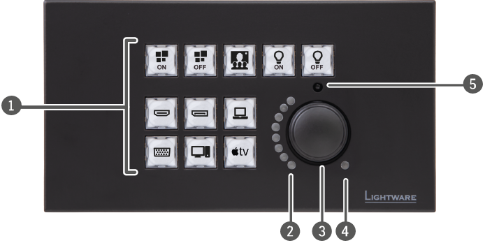
INFO:The labels of the buttons are just for illustration since the button caps are empty by default. The user can insert the desired label from the attached sheet.
|
|
Buttons |
11 configurable buttons with short and long press detection. Each button has a programmable background light. They can be configured for immediate feedback of pushing the buttons or can be set to five different modes: |
||
|
|
Rotary LEDs |
Eight green-colored LEDs for giving feedback about the current position of the jog dial knob. |
||

|
full bright |
As the jog dial is rotated right (and the volume increases), the LEDs turn on one-by-one. One level means half brightness. The picture on the left shows that the volume is set 11. |
||

|
half bright |
|||

|
off |
|||
|
|
Rotary knob |
Jog dial for volume control on a 16-level scale or it can be programmed for other controlling purposes by turning and clicking the knob. |
||
|
|
Mute LED |
It gives feedback about the mute status of the volume. It can be toggled on and off by pushing the rotary knob. |
||

|
on |
The volume is muted. |
||
|
|
off |
The volume is unmuted. |
||

|
blinking |
The device is in bootload mode. Press the rotary knob for 5 sec for changing to the normal operation mode. |
||
|
|
IR detector |
Built-in IR eye to receive infra signal. |
||


|
|
GPIO |
4-pole Phoenix® connector for configurable general purpose. |
|
|
RS-232 port |
3-pole Phoenix® connector for bi-directional serial communication. |
|
|
DC Input |
The device can be powered by a local adaptor. Connect the output to the 2-pole Phoenix® connector. For more information about the powering, see Powering Options section. |
|
|
Ethernet ports |
Two RJ45 connectors for Ethernet communication. Both of them are PoE-compatible, one is a PoE receiver, the other can send PoE (PoE sending is available when the device is locally powered). |
2.2. RAC-B501
2.2.1. Front View

|
|
Power LED |
The LED gives immediate feedback about the current power status of the device. |
||

|
off |
The device is not powered. |
||

|
blinking (green) |
The device is powered on. |
||
|
|
User LED |
Configurable user LED for action feedback purpose. |
||
|
|
Function button |
Special functions are available with the button (DHCP settings, restore factory default settings, condition launching in Event Manager). |
||
2.2.2. Rear View

|
|
GPIO port |
4-pole Phoenix® connector for configurable general purpose. |
|
|
RS-232 port |
3-pole Phoenix® connector for bi-directional serial communication. |
|
|
DC input |
The device can be powered by a local adaptor. For more information see the Powering Options section. |
|
|
Ethernet port with PoE input support |
RJ45 connector for Ethernet communication. The port is PoE-compatible to receive power from a remote device |
|
|
Ethernet port with PoE output support |
RJ45 connector for Ethernet communication. The port is PoE-compatible to send power to a remote device. |
2.3. Special Functions for RAP-B511 Series
2.3.1. Behind the Front Panel


After removing the front plate (no special tool needed, just pull apart by hand), a USB connector, a reset button, and a live led can be seen.
|
|
USB Port |
USB mini-B connector can be used for LDC access or firmware update. |
||
|
|
Reset Button |
Hidden button to restart the device. |
||
|
|
Factory defeault |
Hidden button to reload the Factory Default Settings. |
||
|
|
Live LED |

|
blinking |
The unit is powered and ready to use. |

|
on |
The device is powered, but the CPU is not running. |
||

|
off |
The unit is NOT powered or out of operation. |
||
DIFFERENCE:The hidden button for reloading the factory default settings is available from HW v1.1.
2.3.2. Restarting the Device

Step 1.Keep the 5th and the 9th button pressed for 10 seconds.
Step 2.Release the buttons. The mute LED lights up when the device restarts.
2.3.3. Entering Bootload Mode

It may happen that the firmware update process is unsuccessful and the device cannot be switched to bootload mode automatically. In this case, the device can be forced into bootload mode as follows:
Step 1.Make sure the device is powered off.
Step 2.Press and keep pressed the Rotary knob.
Step 3.Power on the RAP-B511 while the Rotary knob is being pressed. If the device is switched to bootload mode the Mute LED is blinking quickly. Release the knob.
The other LEDs are off. The procedure of firmware update can be found in the Firmware Update chapter.
INFO:Press the rotary for 5 sec to switch the normal operation mode.
2.4. Special Functions for RAC-B501
2.4.1. Programmable Function Button

Action or an operation can be assigned to the Function button as this button press is a condition that can be selected in the Event Manager. See more details in the Event Manager section.
2.4.2. Programmable User LED

Action or an operation can be assigned to the User LED as a condition is fulfilled and the LED responds on that. See more details in the Event Manager section.
2.4.3. Dynamic IP (DHCP) Settings

The device has a static IP address as a factory default setting. If this setting does not fit to the circumstances during install or usage, DHCP can be enabled from the front panel:
Step 1.Make sure the device is powered on and operational.
Step 2.Press and keep pressed the Function button for 5 seconds.
Step 3.After 5 seconds front panel LEDs start blinking; release the button and press it 3 times again quickly (within 3 seconds).
Step 4.The LEDs get dark, DHCP gets enabled. #network #dhcp
2.4.4. Recalling Factory Default Settings

To restore factory default values, do the following steps: #factory
Step 1.Make sure the device is powered on and operational.
Step 2.Press, and keep pressing the Function button for 10 seconds. After 5 seconds the front panel LEDs start blinking, but keep on pressing the button.
Step 3.After 10 seconds the LEDs start blinking faster; release the button and press it 3 times again quickly (within 3 seconds).
Step 4.The LEDs get dark, the device restores the Factory Default Settings and reboots.
#new
The chapter is about the installation of the device and connecting to other appliances, presenting also the mounting options and further assembly steps.
3.1. Mounting Options for RAP-B511 Series

The caps of the buttons are supplied separately with the product in a plastic bag. The list of supplied labels can be seen in the Supplied Button Labels for RAP-B511 series section. Select the desired label and insert it as shown in attached figure:
Step 1.Insert the label.
Step 2.Place the cap and pay attention to the nut; the direction of the buttons are different, thus, certain caps must be rotated by 90°.
3.1.2. Compatible Outlet Box Types
The room automation panel can be easily mounted into an industrial standard switch/outlet box. See more details about the exact sizes of the device in the Mechanical Drawings section.
Model name refers to the box type, see the recommended box types for the models in the table below:
|
Model |
Outlet box type |
|
RAP-B511-EU |
Double EU wall box (65mm) (e.g. Legrand: 0 801 22, 0 800 52, 2x0 801 51, 2x0 801 61, 0 819 42) |
|
RAP-B511-UK |
Double UK wall box (e.g. Appleby SB628 Galvanised Steel Knockout boxes 2G 47mm) |
|
RAP-B511-US |
Double US wall box (e.g. Carlon B225R-UPC Switch/Outlet Box, 2-Gang, Depth: 2-3/4”) |
INFO:The outlet box is not supplied with the product, it can be purchased from the local hardware store.
3.1.3. Dimensions
|
Model |
Dimensions (mm) |
|||
|
a |
b |
c1 |
c2 |
|
|
RAP-B511-EU |
152 |
82 |
40.5 |
17.6 |
|
RAP-B511-UK |
140 |
80 |
40.5 |
17.6 |
|
RAP-B511-US |
115.9 |
115.9 |
40.5 |
17.6 |

3.1.4. Mounting RAP-B511-EU into the Outlet Box
Step 1.Pull apart the Front plate from the RAP-B511-EU by hand (no special tool needed).

Step 2.Place two screws (marked with red color) OR four screws (marked with yellow color) in the holes.
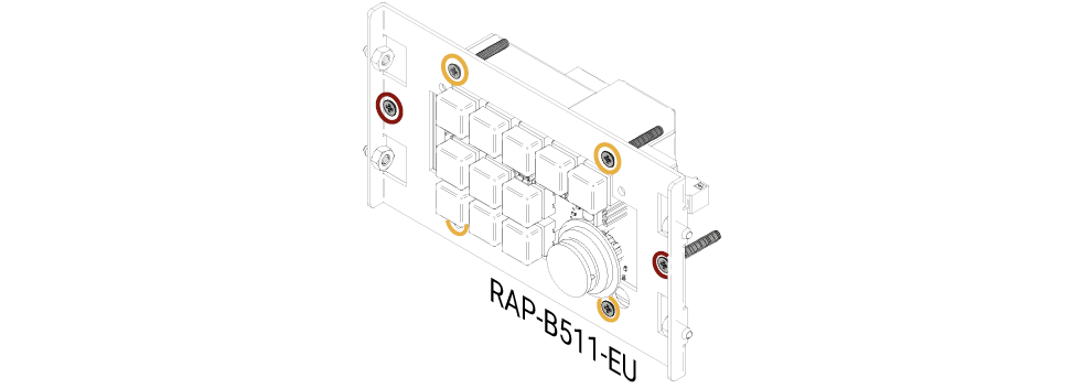
Step 3.Insert the RAP-B511-EU into the Outlet box and position it to get the holes aligned.
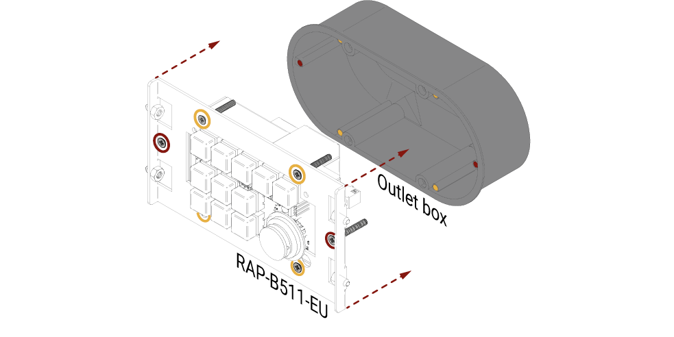
Step 4.Fasten the front side of the device to the Outlet box by fitting all the screws.
Step 5.Place back the Front plate to the Button panel.

See more details about the exact sizes of the RAP-B511-EU in the Mechanical Drawings section.
3.1.5. Mounting RAP-B511-UK into the Outlet Box
Step 1.Pull apart the Front plate from the RAP-B511-UK by hand (no special tool needed).

Step 2.Place the screws (marked with yellow) in the holes.

Step 3.Insert the RAP-B511-UK into the Outlet box and position it to get the holes aligned.

Step 4.Fasten the front side of the device to the Outlet box by fitting all the screws.
Step 5.Place back the Front plate to the RAP-B511-UK
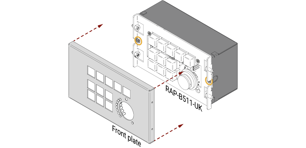
See more details about the exact sizes of the RAP-B511-UK in the Mechanical Drawings section.
3.1.6. Mounting RAP-B511-US into the Outlet Box
Step 1.Pull apart the Front plate from the RAP-B511-US by hand (no special tool needed).

Step 2.Place four screws (marked with yellow) in the holes.

Step 3.Insert the RAP-B511-US into the Outlet box and position it to get the holes aligned.
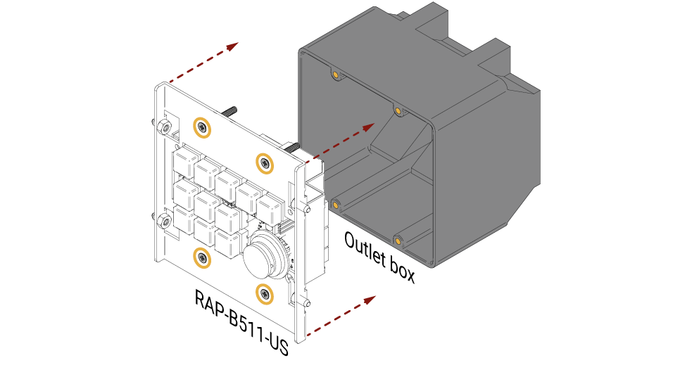
Step 4.Fasten the front side of the device to the Outlet box by fitting all the screws.
Step 5.Place back the Front plate to the RAP-B511-US

See more details about the exact sizes of the RAP-B511-US in the Mechanical Drawings section.
3.2. Mounting Options for RAC-B501
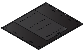
3.2.1. Rack Shelf Mounting

DIFFERENCE:Only RAC-B501 model can be installed to a rack shelf.
Allows rack mounting for half-rack, quarter-rack and pocket sized units.
1U high rack shelf provides mounting holes for fastening two half-rack or four quarter-rack sized units. Pocket sized devices can also be fastened on the self.

WARNING!Always use M3x4 screws for fastening the device to the rack shelf. Using different (e.g. longer) ones may cause damage to the device.
INFO:The screws for the rack frame are not supplied to the device.
3.2.2. Under-Desk Mounting
DIFFERENCE:Only RAC-B501 model can be installed under a desk or furniture.
|
Accessory |
Number of mountable devices |
Features |
|
|
UD Mounting Plate F110 |

|
1 quarter-rack sized |
Lightweight design |
|
UD Mounting Plate F120 |

|
2 quarter-rack sized |
Lightweight design |
|
UD Mounting Pro P110 |

|
1 quarter-rack sized |
Easy to change the mounted device |
|
UD Mounting Pro P140 |
|
2 quarter-rack sized |
Easy to change the mounted devices |
INFO:For more details about the options of the applications and the assembly steps, please download the Mounting Accessory Guide from our website: https://lightware.com/pub/media/lightware/filedownloader/file/Assembly-Guide/Mounting_AG.pdf
#new
3.3. Electrical Connections
3.3.1. 48V DC Connection
RAP-B511 series is built with 2-pole Phoenix connector for 48V DC 1A power connection.

2-pole Phoenix connector and plug pin assignments
3.3.2. GPIO - General Purpose Input/Output Ports
RAP-B511 series contains a 4-pole Phoenix connector with three GPIO pins, which operates at TTL digital signal levels and can be set to high or low level (Push-Pull). The direction of the pins can be input or output (adjustable). Voltage ranges for GPIO inputs are the following:
|
Input voltage [V] |
Output voltage [V] |
Max. output current [mA] |
|
|
Logical low level |
0 - 0.8 |
0 - 0.5V |
30 |
|
Logical high level |
2 - 5 |
4.5 - 5V |
18 |

GPIO connector and plug pin assignments
INFO:The maximum total current for the three GPIO pins is 180 mA.
Compatible plug type
Phoenix® Combicon series (3.5mm pitch 4-pole), type: MC 1.5/8-ST-3.5.
3.3.3. USB Connector
Behind the front panel there is a standard USB mini-B receptacle.
The device contains a 3-pole Phoenix connector which is designed for RS-232 serial connection.

RS-232 connector pin assignments
RS-232 Output Voltage Levels
▪Logic low level: 3V .. 15V
▪Logic high level: -15V .. -3V
Compatible Plug Type
Phoenix® Combicon series (3.5mm pitch, 3-pole), type: MC 1.5/3-ST-3.5.
You can find more information about RS-232 in Settings for Control Interfaces section.
INFO:The RAP-B511 series operates as a DCE unit according to its pin-out.
The room automation panel is supplied an RJ-45 connector for Ethernet/LAN connection for local control functions.
Wiring of LAN Cables
Lightware recommends the termination of LAN cables on the basis of TIA/EIA T 568 A or TIA/EIA T 568 B standards.

RAP-B511 series and RAC-B501 automation panels are compatible with IEEE 802.3af standard - Power over Ethernet (PoE) - and one Ethernet port can receive and the other one can send power over the Ethernet line.
The room automation panel can be powered by any of the following ways:
Local adaptor and remote power (PoE OUT)
When it is locally supplied with 48V DC adaptor, the room automation panel is able to send remote power via POE OUT RJ45 connector to other PoE-compatible device.
Remote power injector (PoE IN)
The devices can be powered remotely by a PoE-compatible power injector, like a PoE-compatible switch. Connect it to the POE IN labeled RJ45 connector.
Standalone Matrix or Matrix board (PoE IN)
Powering by a matrix board* over the CATx (TPS) cable. The output board needs to be powered by an external PSU. Connect it to the POE IN labeled RJ45 connector.
* TPS2 I/O board with PoE extension (-P)
INFO:Over the CATx cable, the Ethernet communication is transmitted.
|
Local adaptor and |
Remote power injector (PoE in) |
Matrix board (PoE in) |

|
||
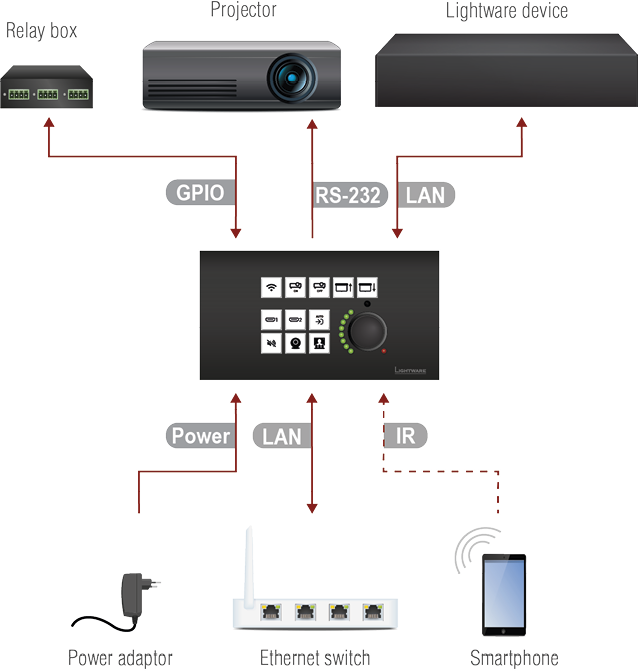
3.5. Connecting Steps
|
|
Connect a controller/controlled device (e.g. relay box) to the GPIO port. |
|
|
For RS-232 extension: connect a controller/controlled device (e.g. Projector) to the RS-232 port. |
|
|
▪Connect the device to a LAN network in order to control the device. ▪Connect a PoE-compatible device for remote powering and control to the PoE out LAN port. |
|
|
Built-in infra detector is ready to receive any IR signal without user intervention. |
|
|
Powering on the devices is recommended to do as the final step during the installation. Please check the Powering Options section for the details. |
DIFFERENCE:Infrared connection is only available for RAP-B511 series panels. RAC-B501 is not built with IR detector.
The following chapter describes the features of the device with a few real-life examples.
4.1. General Concept
Room automation panel is designed for advanced control functions. Industrial standard communication interfaces (RS-232, Ethernet, GPIO, IR) ensure the compatibility with third-party units or Lightware products. They make automating the whole AV system in a huddle room possible.
Customizing the control functions can be done by making connections between the proper inputs (triggers or conditions) and the desired outputs (actions). These settings can be done from a computer using the Software Control - Lightware Device Controller (LDC) software or via LW3 protocol commands (for more details see LW3 Programmers’ Reference section).
Inputs may come from:
▪The Room Automation Panel by pushing (or releasing) the button, turning or pushing the rotary switch. *
▪Real-Time Clock (e.g. when the local time is equal 12:00 the action is executed).
▪Other incoming signals: detected IR codes, recognized RS-232 messages, GPIO level changes.
Outputs can be the followings:
▪Button LEDs of the Room Automation Panel. *
▪Send messages (or signals) to the other device: RS-232 message sending, TPC/UDP message sending, GPIO output state changing.
* Only for RAP-B511 series models.

4.2. Inputs 1. - User Interactions
DIFFERENCE:This section relates to RAP-B511 series models only. RAC-B501 model is not built with buttons and rotary switch.
The operation of the RAP-B511 series is based on user interactions such as button press, or turn the rotary. These are the main triggers (or inputs) of the control functions. They can be quickly and easily customize in UI Config Menu of the Software Control - Lightware Device Controller (LDC) software.

The RAP-B511 has 11 configurable buttons, and two main button states are defined: Pressed and Released.
Operation mode is an attribution of the button, which declares the button behavior when it is pressed or released. Three different operation modes are available: momentary, toggle and radio group (1-5).
The chosen operation mode defines how the interaction state changes when the button is pressed or released (see the details about it in the table on the right). The true or false value of the interaction state triggers the button LED function and the desired action.
Momentary operation mode
Simple button function, when the button is pressed, the action will be executed.
Example: Roll down the shades with keeping the button pressed. When the button is released, the shades stop.
Explanation: When the button is pressed, the interaction state changes true, when the button is released, the interaction state changes false.
Toggle operation mode
This button type toggles between two states.
Example: Turn on and off the light with one button.
Explanation: When the button is pressed, the interaction state changes true, when the button is released, the interaction state does not change. When the button is pressed once again, the interaction state changes false.
Radio group operation mode
It defines the assigned radio group of the button. One button can belong to one group at the same time. Five groups are available, one group may contain max. 11 buttons.
Example: Select video input on a crosspoint or switcher. One input can be active at the same time.
Explanation: When the button is pressed, the interaction state changes true and the interaction state of the other group members are false. When the button is released, the interaction state does not change.
Summary of the button operation modes
|
Momentary Operation Mode |
||||
|
PRESS |
RELEASE |
PRESS |
RELEASE |
|

|

|

|

|
|
|
interaction state |
||||
|
true |
false |
true |
false |
|
|
Toggle Operation Mode |
||||
|
PRESS |
RELEASE |
PRESS |
RELEASE |
|
|
|

|

|
|
|
|
interaction state |
||||
|
true |
true |
false |
false |
|
|
Radio Group Operation Mode |
||||
|
PRESS |
RELEASE |
PRESS |
RELEASE |
|

|

|

|

|
|
|
interaction state |
||||
|
true false false |
true false false |
false true false |
false true false |
|
Flowchart of the button configuration process

INFO:All settings of the button functions are available in the Lightware Device Contoller software (see the details in Buttons section) or via LW3 protocol commands (for more details see Button Configuration section).
4.2.2. Rotary
The jog dial knob is designed for volume control (in a 16-level scale), but it can be used for other controlling purposes, too.
Turning left and right the rotary changes the volume value from 0 to 16. The volume values are the conditions, which are assigned to the control commands (e.g. SET /MEDIA/PORTS/VIDEO/O2/ANALOGAUDIO.VolumedB=-96\x0d\x0a). When the rotary reaches the proper position, the action will be executed.
The control command can be sent over RS-232 or Ethernet (in this case, the IP address of the target device is needed).
LWR Volume Control Schema supports to load the LW3 command list automatically for controlling the volume (and the mute/unmute state) of the Lightware devices. Choose the proper schema (see more details about the compatibility table in Configurations of the Rotary section) and fill the audio port number.
Custom Volume Control Schema makes it possible to configure any command for controlling a third-party device.
Knob press toggles between the muted and the unmuted states. When the Custom schema is loaded, press and release event can be configure for any purpose.
Flowchart of the rotary configuration process

INFO:Customizing the rotary functions is possible with Lightware Device Contoller software (the details can be found in Configurations of the Rotary section) or with LW3 protocol commands (for more details see Volume Control Configuration section).
4.3. Inputs 2. - Automation Options
The below-listed features give an opportunity to "automate" the control system, and the Room Automation Panel reacts to the inputs automatically, user intervention is not necessary.
These inputs can be set as a condition in the Event Manager in the Software Control - Lightware Device Controller (LDC) software. They trigger the desired actions.
The real-time clock feature supports the storage of the exact time in the device. The time can be programmed as a condition in the event manager: single and weekly repetitive events may be configured with this function. Local time elements (years, months, days, etc.) help customize the proper timing of the actions.
A BR1632A battery is supplied with the product, it ensures the fluent operation of the built-in timer while the device is not powered.
The battery is designed for life-long usage in a fixed installation, so it cannot be replaced!
Real-Time Clock Settings
The flowchart below displays the correlation of the time properties. The red colored settings can be defined by the user, the others generated automatically.

Flowchart of the real-time clock configuration process
INFO:All settings of the Real-time clock is possible using the Lightware Device Contoller software (see the details in Time Settings section) or via LW3 protocol commands (in the Time Settings section).
This tool is able to recognize and store the incoming RS-232 message until the previously defined string (delimiter) has arrived or the timeout has elapsed after the last data. The last incoming serial data is stored and it can trigger an action in Event Manager.
ATTENTION!The recognizer function works when the operation mode of the RS-232 port is control or command injection (in this case, one of the Ethernet socket have to be opened). For more details about the operation modes, see the Serial Interface section.
The lamp can be turned on and off both with the light switch and the RAP-B511. When the lamp is turned off by the switch, the relay box sends an RS-232 status message to the RAP-B511 to inform it that the lamp was turned off. When the lamp is controlled with the RAP-B511 the next time, the device sends the 'turn on' command to the relay box of the lamp. This example shows how to syncronize the same control function in the RAP with another device.
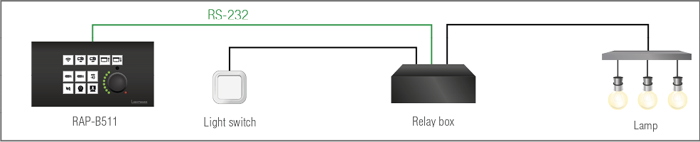
At first, configure the recognizer for the serial communication, after that, configure the Button1.
Step 1.Enable the operation of the recognizer, set an optimal timeout (e.g. 30 ms). Set the RS-232 operation mode to Control.
The flowcharts below show the process of the system. The blue highlight boxes display the settings connected to the RS-232 recognizer.
Turn on the lamp

Turn off the lamp

Do the following setting on the UI Config page:
Step 2.Select the Button1 and set the operation mode to Toggle. The first button press changes the interaction state to true. It happens automatically.
Step 3.Choose the TRUE feedbacks tab and click on the RS-232 message recognized condition. Write the serial message that is sent by the relay box about the lamp status in the entry field of the pop-up window (e.g. 'the lamp is turned on'). Click on Ok to save.
Step 4.Choose the FALSE feedbacks tab and click on the RS-232 message recognized condition. Write the serial message that is sent by the relay box about the lamp status in the entry field of the pop-up window (e.g. 'the lamp is turned off'). Click on Ok to save.
The RS-232 recognizer settings need to be done with Lightware Device Controller Software (see details in the RS-232 Message Recognizer section) or with LW3 protocol commands (see more information in the RS-232 Message Recognizer section).
For more information about the button configuration, see the UI Config Menu section.
DIFFERENCE:The features mentioned below are available from FW package v1.1.0b3.
The feature is almost the same as in case of the RS-232, but for the network interface: the incoming TCP messages can be processed, which may trigger actions. The combination of the TCP recognizer and the Event Manager gives numerous opportunities for creating automatic room solutions.
TCP Recognizer Example
When the Projector switches off, the button light (2) of the RAP-B511 is turned off automatically.

When the power-off process is started in the projector, it will send a message over Ethernet. That message will be recognized by the RAP-B511 and will be used as a Condition in Event Manager.
How to set up the RAP?
Step 1.Configure the recognizer for the communication by the LDC, (see the Ethernet section) or by LW3 protocol commands (see the TCP Message Recognizer section). Define the desired device as a TCP client. (The Projector is saved as 'C1' in this example.)
Step 2.Create the following event in the Event manager:
E1. When the (PWR!001 "On") message is recognized from the C1 client, the Background light of Button LED2 is set to Off state.
For more information about setting the events in LDC, see the Event Manager section.
DIFFERENCE:This section relates to RAP-B511 series models only. RAC-B501 model has no built-in Infrared detector.
The RAP-B511 has a built-in IR eye with IR recognizer function. The incoming signal is stored in hash (fingerprint), and it can trigger actions in Event Manager.
INFO:All settings are available in the LDC software, more details can be found in the Infra section.
IR Recognizer Example
IR signals are sent by the Remote controller, the projector is connected to the Ethernet port of the RAP-B511.

The projector can be powered on via the RAP-B511 by using the remote controller with the following way:
▪Set an action in Event Manager: if the power button is pressed on the Remote controller, the RAP-B511 sends a control command ('Power on') to the projector via Ethernet. In this case you can control the device via the RAP-B511 remotely. See the details about the Event Manager settings in the Event Manager section.
4.3.5. GPIO Input Level Change
The GPIO (General Purpose Input/Output) port is a multifunctional input/output interface to control the RAP-B511 / RAC-B501 or third-party devices and peripherals. You can establish connection between the controller/controllable device and the RAP-B511 / RAC-B501 by the 4-pole Phoenix connector. Three pin's direction is configurable independently based on needs of the application.
When the GPIO pin is used as an input, it is able to receive feedbacks from the other device by changing the input level. The configuration is available in UI Config Menu and the Event Manager.
Outputs of the Room Automation Panel can be a feedback about the executed event (e.g. after the button press the button LED lights) or a control signal to the other device. Outputs can be set in the UI Config Menu (and in the Event Manager) in the Software Control - Lightware Device Controller (LDC) software.
4.4.1. Button LED Configuration
DIFFERENCE:This section relates to RAP-B511 series models only. RAC-B501 model is not built with buttons.
Button LEDs are customizable feedback of the user interaction or any input that is set as a condition. The LED behavior takes into consideration of the status of the interaction states. For more details about it, see the Buttons section. The button LEDs can be configured separately.
LED states
Six different LED behaviors are available:
Off / Low brightness / High brightness / Blinking / Slow blinking /Sine pulse
Default LED intensity
Low brightness and High brightness intensity can be customized in 0-5 level scale where 0 means no light, 5 means maximum intensity.
The factory default value of the low brightness: 2
The factory default value of the high brightness: 5
This setting is available in the LDC in the Front Panel Settings section or with LW3 protocol commands (for more details, see the Configure Button section).
Default LED function
The button LED can get a default function where two cases are defined:
▪LED function for true state (when the interaction state is true)
Example: Button1 is in Momentary operation mode, so when it is pressed, the interaction state changes true. If the LED function for true state is on, the button LED will turn on while it is pressed.
▪LED function for false state (when the interaction state is false)
Example: Button2 Button3, Button4 are in the same radio group. When Button2 is pressed, its interaction state changes to true and the other's interaction states change to false. If the LED function for false state is off (of all buttons in the group), the LEDs of Button3 and Button4 will turn off.
Momentarily LED function
The Button LED can get a momentarily function. This overwrites the default function for a while. Duration time has to be set if the LEDs momentarily function is off / low bright /high bright. Blinking number is required when the LEDs momentarily function is blinking.

LED function settings has to be done with Software Control - Lightware Device Controller software (in UI Config Menu section) or with LW3 protocol commands (for more details see Button LED Configuration section).
4.4.2. Rotary LEDs
DIFFERENCE:This section relates to RAP-B511 series models only. RAC-B501 model is not built with rotary switch.
Rotary LEDs always display the actual position of the rotary. For more details about it, see the RAP-B511 Series section.
4.4.3. Serial Message Sending
The Room Automation Devices can send serial messages via RS-232 port in order to control the other devices. This function can be set as an action which executed after the trigger condition (e.g. buttonpress).
Preparations and Settings
▪The RS-232 port settings (baud rate, data bits, parity, stop bits) of the connected serial devices must be the same.
▪The RS-232 port of the RAP-B511 must be in Disconnect mode. (If the target device is also Lightware unit, take care of the its operation mode, too)
▪Pay attention to the correct serial cabling (connector pinout). For more details about the cabling, see Factory Default Settings section.
The configuration is available in the UI Config Menu and the Event Manager. The details about serial message sending are available in the RS-232 Message Sending section or in the Message Sending Application Note.
4.4.4. Ethernet Message Sending
The RAP-B511 and RAC-501 devices can send TCP or UDP messages via Ethernet port in order to control the other devices. This function can be set as an action which executed after the trigger condition (e.g. buttonpress).
Preparations and Settings
▪Pay attention to the TCP/IP port no. (and have it opened) settings in the connected devices. (The Ethernet has to be enabled at the TPS and Ethernet ports.)
▪The Ethernet devices must be in the same subnet.
▪If you have problems with accessing a device over Ethernet, try to check the connection e.g. by pinging the IP address.
All settings are available in UI Config Menu and the Event Manager. The details about Ethernet message sending is available in the Ethernet Message Sending section or in the Message Sending Application Note.
4.4.5. HTTP Post and Put Message Sending
ATTENTION!This feature means posting or putting HTTP messages from the Lightware device to another device. Encrypted transmission (HTTPS) is not supported.
This feature allows sending HTTP post and put messages to the desired server IP:port no. Control commands can be set to the target device, but it is not suitable for processing the response (e.g. querying a parameter/status).
The feature is available in the LDC, see the HTTP Clients (HTTP Post and Put Message Sending) section, and by LW3 commands, see the HTTP Messaging section.
4.4.6. GPIO Output Level Change
The GPIO (General Purpose Input/Output) port is a multifunctional input/output interface to control the RAP-B511 or third-party devices and peripherals. You can establish connection between the controller/controllable device and the RAP-B511 by the 4-pole Phoenix connector. Three pin's direction is configurable independently based on needs of the application.
When the GPIO pin is used as an output, it is able to send a TTL signal the other device by changing the output level. GPIO output level change can be set as an action.
The configuration is available in UI Config Menu and the Event Manager.
GPIO Example
The projection screen is moved up and down by Relay box when the Button2 or the Button3 is pushed. Relay box is controlled by the GPIO port.

Step 1.Select the Button2 and Button3 set their operation mode to Radio Group1.
Step 2.When the Button2 is pressed, it triggers the P1 pin of the GPIO to high level (it closes the Relay and the projection screen is rolled down). Select the Button2 and choose the Turn ON actions tab. Click on the Set output state to 'High' action and set the P1 output port. Click OK to save.
Step 3.When the Button3 is pressed, it triggers the P1 pin of the GPIO to low level (it opens the Relay and the projection screen is rolled up). Select the Button3 and choose the Turn ON actions tab. Click on the Set output state to 'Low' action and set the P1 output port. Click OK to save.
ATTENTION!Please always check the electrical parameters of the devices what you want to control. The maximum current of one GPIO pin is 30 mA, the maximum total current for the three pins is 180 mA.
See the LDC settings for GPIO port in the GPIO section. See also the details about the button configuration, in the UI Config Menu section.
4.5. Settings for Control Interfaces
Technical Background
Serial data communication can be established via the local RS-232 port (Phoenix connector). Three different RS-232 modes can be set for the serial port: Disconnect, Control mode, or Command Injection; see the figure below.

Serial port diagram of Room Automation Panels
The following settings are defined:
|
|
The serial port is in Disconnect mode. |
|
|
The serial port is in Control mode. |
|
|
The serial port is in Command Injection mode. |
INFO:All settings are available in the LDC software, see details in the RS-232 section.
Only one mode can be used at a time: Disconnect, Control mode, or Command Injection mode.
Disconnect Mode
This mode is for sending control commands to a third-party (or a Lightware) device from the RAP-B511. ASCII characters and binary data in hexadecimal format can be used in this case.
Control Mode
The incoming data from the given port is processed and interpreted by the CPU. The mode allows to control the device directly. LW2 or LW3 protocol commands are accepted – depending on the current port setting.
INFO:Serial message sending is available in control mode.
Command Injection Mode
In this mode, the device works as a TCP/IP <-> RS-232 bidirectional converter. The TCP/IP data is converted to RS-232 data and vice versa. For this operation separated TCP/IP port number is defined (independent of the basic ones which are used for device control over TCP/IP).
4.5.2. Ethernet Interface
The device can be controlled via Ethernet (standard RJ45 connector). This interface supports:
▪Configure the device with Lightware Device Controller. For more information about the LDC, see Software Control - Lightware Device Controller section.
▪Control Lightware devices with LW2 and LW3 command protocols. See more details about the Lightware protocols in LW2 Programmer's Reference and LW3 Programmers’ Reference sections.
▪Establish the connection to Lightware Device Updater v2 software and perform a Firmware Update.
▪Create local network, passthrough the Ethernet data traffic.
About PoE
The Ethernet ports of the RAP-B511 are in accordance with IEEE 802.3af (PoE) standard. One Ethernet port can receive and the other one can send power over the Ethernet line. For more information about the PoE function, see Powering Options section.
INFO:PoE-compatible and not compatible devices can be connected simultaneously as the feature can be set individually on each port.
Example

The Room Automation Panel sends PoE via Ethernet to the PoE-compatible display outside the meeting room, which shows the availability of the room.
4.5.3. USB Control Interface
The device can be controlled over front panel USB mini B-type connector. The interface can be used to establish a connection to Lightware Device Controller. For more information about the LDC, see Software Control - Lightware Device Controller section.
This interface only supports LW3 protocol. See more details about the Lightware protocols in LW3 Programmers’ Reference sections.
Establish the connection via USB to Lightware Device Updater v2 software and perform Firmware Update.
DIFFERENCE:This section relates to RAP-B511 series models only. RAC-B501 model is not built with Infrared detector.
Technical background
RAP-B511 contains dedicated IR in connection and is able to receive IR signal via the built-in IR detector units. The signal is stored in hash (fingerprint)format.
With the help of the device's IR recognizer functionality you can assign actions in Event manager (for more details, see IR Recognizer section). The second option is the command injection mode (like at Serial Interface in the previous section) where you can send IR commands over LAN. Command injection mode can be turned on and off on the input port.

Port diagram of the IR interface
INFO:All settings are available in the LDC software, see settings in the Infra section.
4.6. The Event Manager Feature
The Event Manager feature means that the device can sense changes on its ports and is able to react according to the pre-defined settings. Lightware Device Controller contains a user-friendly software tool and allows creating Events by defining a Condition and an Action.

Event Manager Example
See more information about the settings in the Event Manager section in LDC.
Event Manager +
DIFFERENCE:Below mentioned features are available from FW package v1.1.0b3.
The AND Operator
The practical experience has shown that there is a need to examine more conditions (up to four) as follows: if one of the set conditions becomes true (while the other conditions are fulfilled), then the set Action is launched. For example, in a meeting room we have the following situation:
▪Signal is present on an input port,
▪A GPIO pin state becomes ’low’ (by an external device).
If the two Conditions are present at the same time, the Action is launched. Just create the two Conditions into separate Events, then create a third Event, select the two Conditions and define the Action.
See the Combine Links section for the settings in LDC.
Event Manager Variables
A brand new area is opened by implementing the variables. You can create custom variables (max. 30 pcs.) in number or text format which can be used in the Event Manager. The variables can have the following properties/methods:
▪Numeric (integer) type with min/max value setting, or string-type (the type is set automatically)
▪Increment/step the numeric value,
▪Value-dependent case operations,
▪Reading and storing the value of an LW3 property into a string or a numeric variable.
The defined variables are stored in a non-volatile memory and the value is kept in case of a reboot. The new opportunities allow creating a monitoring/controlling system without connecting an additional control processor.
See the Variables section for the settings in LDC.
Condition Trigger
This improvement in the Event Manager works as if a condition is detected. When a complex control system is built, a Condition may trigger numerous Actions. A typical example is when a system is powered on and the ’ready-to-use’ state has to be loaded. In this case, there could be many actions which are based on the same condition. In order to reduce the number of the commands, you can trigger one ’key’ condition, which could start the whole process. See the Condition Triggering section for the settings in LDC.
4.7. Basic IT Security
DIFFERENCE:Below mentioned features are available from FW package v1.1.0b3.
These entry-level network security improvements help to prevent unauthorized access to the Lightware device:
▪Cleartext login
▪IP Port Block
▪MAC Filtering
The Cleartext Login tool allows setting a password for login, thus, the device will not accept any command coming from an interface (RS-232, Ethernet, etc…), only the device type and the serial number can be queried without login. You can set all affected TCP/IP ports individually to enable or disable.
The IP Port Block feature is an additional protection for the Cleartext login. There are TCP/IP ports in Lightware devices which are not protected by the login, so you can disable them if necessary. Example: due to the working method of the LW2 communication, the Cleartext login does not provide protection when LW2 command is sent to the device, that is why the TCP port no.10001 shall be blocked manually.
Another level of security is the MAC Filtering tool. You can create an ’allowlist’ of network devices based on the MAC address which are allowed:
▪Controlling the device (Send option), or
▪Querying parameters (Receive option) to/from the Lightware device.
Below table shows the protection levels of these features.
|
IP Port |
Function |
MAC Filter |
Cleartext Login |
IP Port Block |
|
80 |
HTTP Post&Get |
|
- |
|
|
81 |
LW3 control (miniweb) |
|
|
- |
|
6107 |
LW3 protocol |
|
|
- |
|
800x |
Command injection (RS-232) |
|
- |
|
|
900x |
Command injection (IR) |
|
- |
|
|
10001 |
LW2 protocol |
|
- |
|

ATTENTION!Be careful when combining these functions; improper settings may cause malfunction.
Most of these feature are available in LDC, see the Settings Menu section.
4.8. Batch Commands
DIFFERENCE:Below mentioned features are available from FW package v1.1.0b3.
These features can be used to process a group of pre-defined commands. The commands can be stored in the device as macros or you can save the commands in a plain text file and send the device by an HTTP message.
LW3 over HTTP (Command Salvo)
This feature allows the LW device to be controlled over HTTP. In this case, a batch of commands is sent over HTTP to the Lightware device for processing. Save the LW3 commands into a file, post it to the <IP_address>/protocol.lw3 file and the commands are processed immediately.
Running Macros
In this case, the command sequences (macros) are stored in the device. You can create your custom macros in a file, upload into the device and run at any time. The number of the macros depends on the device type, at most 50 macros can be saved in the device. See more information about the feature in the Macros section.
5. Software Control - Lightware Device Controller
The device can be controlled by a computer through the Ethernet and RS-232 port using Lightware Device Controller (LDC). The software can be installed on a Windows PC or macOS. The application and the User’s manual can be downloaded from www.lightware.com.
5.1. Install and Update
Installation for Windows OS
ATTENTION!The minimum display resolution shall be 1280x720.
Step 1.Run the installer. If the User Account Control drops a pop-up message click Yes.
Step 2.During the installation you will be prompted to select the type of the installation: normal and the snapshot install:
|
Normal install |
Snapshot install |
|
Available for Windows and macOS |
Available for Windows |
|
The installer can update only this instance |
Cannot be updated |
|
Only one updateable instance can exist for all users |
Different versions can be installed for all users |
Comparison of the Installation Types
ATTENTION!Using the Normal install as the default value is highly recommended.
Installation for macOS
INFO:After the installation, the Windows and the Mac application has the same look and functionality. This type of the installer is equal with the Normal install in the case of Windows and results an updateable version with the same attributes.
Mount the DMG file with double clicking on it and drag the LDC icon over the Applications icon to copy the program into the Applications folder. If you want to copy the LDC into another location just drag the icon over the desired folder.
ATTENTION!Please check the firewall settings on the macOS device. LDC needs to be added to the exceptions of the blocked software for the proper operation.
The Updating of the LDC
Step 1.Run the application.
The Device Discovery window appears automatically and the program checks the available updates on Lightware’s website and opens the update window if LDC updates are found. The current and the update version number can be seen at the top of the window and they are shown in this window even with the snapshot install. The Update window can also be opened by clicking the About icon and the Update button.
Step 2.Set the desired update setting in the Options section.
▪If you do not want to check for the updates automatically, uncheck the circle, which contains the green tick.
▪If you want to postpone the update, a reminder can be set with different delays from the drop down list.
▪If the proxy settings traverse the update process, set the proper values then click the OK button.
Step 3.Click the Download update button to start the updating.
The updates can be checked manually by clicking the Check now button.
5.2. Running the LDC

The common way to start the software is double-click on the LDC icon. But the LDC can be run by command line parameters as follows:
Connecting to a Device with Static IP Address
The LDC is connected to a device with the indicated static IP address directly; the Device Discovery window is not displayed. When the port number is not set, the default port is used: 10001 (LW2 protocol). For LW3 devices use the 6107 port number.
Format: LightwareDeviceController -i <IP_address>:<port>
Example: LightwareDeviceController -i 192.168.0.20:6107
Connecting to a Device via a Serial Port
The LDC is connected to a device with the indicated COM port directly; the Device Discovery window is not displayed. If no Baud rate is set the application will detect it automatically.
Format: LightwareDeviceController -c <COM_port>:<Baud>
Example: LightwareDeviceController -c COM1:57600
Adjusting the Zoom
The window can be zoomed to a specific value to fit to the resolution of the desktop (higher/lower). '1' is the default value (100%).
Format: LightwareDeviceController -z <magnifying_value>
Example: LightwareDeviceController -z 1.2
ATTENTION!The last set value is stored and applied when LDC is started without a parameter.
5.3. Establishing the Connection
Step 1.Connect the device to a computer via Ethernet (RS-232 or USB).
Step 2.Run the controller software; device discovery window appears automatically.
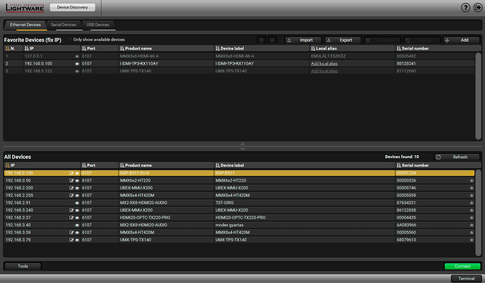
Device Discovery Window in LDC
Changing the IP Address 

To modify IP address settings quickly it is not necessary to enter the device's settings/network menu, you can set them by clicking the pencil icon beside the IP address. In this window you can see only the new settings.
Identifying the Device 
Clicking on the icon results the blinking of the LEDs for 10 seconds. The feature helps to identify the device itself.
The Ethernet tab consists of two lists:
▪Favorite Devices: You can add any Lightware device that is connected via Ethernet and no need to browse all the available devices. Devices can be added by pressing the Add button or marking the desired device by the  symbol in the All Devices list.
▪All Devices: The Lightware devices are listed which are available in the connected network.
Step 3.Select the unit from the discovered Ethernet devices or under Serial devices; when the device is connected through RS-232 click on the Query button next to the desired serial port to display the device’s name and serial number. Double click on the RAP-B511 or select the device and click on the Connect button.
ATTENTION!When the device is connected via the local RS-232 port, make sure that Control mode and LW3 protocol are set on the serial port.
Import/Export the List of Favorite Devices
DIFFERENCE:This feature is available only from LDC version v2.5.5.
The list of favorite devices can be exported/imported by the dedicated buttons (saved as *.JSON file). The list can be imported later (in another computer, too), but please note that the current list will be overwritten by the imported list.
Favorite Devices (fix IP) 
Clicking on the grey star icon next to of the discovered devices the most used units can be saved to the Favorite devices.
ATTENTION!Only the devices set with static (fix) IP address can be saved as favorite device.
Once the device is set as favorite, the star icon will be highlighted with yellow and the device will be displayed between the Favorite Devices (fix IP) window section.

|
|
Information ribbon |
The label shows the device label which can be edited in the Settings menu - Status tab. Device discovery window can be displayed by clicking on this ribbon. Hover the mouse cursor to the information ribbon; the device label and the IP address of the device will appear as a tooltip text. |
|
|
Main menu |
The available menu items are displayed. The active one is showed with dark grey background color. |
|
|
Button Properties |
Basic button settings (e.g. button name, operation mode) can be done in this section. See more details in Button Properties section. |
|
|
Summary of the Button Interactions |
This section contains all the defined events of the selected button. For more details about it, see Button Interactions section. |
|
|
Advanced View button |
Displaying Advanced View Window, showing the Terminal window and the LW3 protocol tree. |
|
|
Configure button section |
The tabs consist of actions and conditions which can be set to the selected button. The tab denomination depends on the button operation mode. The wireframe view of the buttons can be customized by icons and text on the Style tab. For more details about it, see Configure Button section. |
|
|
Wireframe view |
Wireframe view shows the configurable button (or the rotary) with highlight color and shows the buttons in the same radio group, too. Click one to select and adjust it. |


Legend of the Wireframe View

Click the button icon on the wireframe view to display and modify the related configuration.
ATTENTION!Clicking the button icon on the wireframe view does not simulate the button click. Test Button Press button is for that purpose.

The following settings are available in the Button Properties section:
▪Button enabled: The buttons can be enabled or disabled independently of each other (when the button is disabled, pressing it will have no effect).
▪Button name: The button name can be 32 character-long, ASCII characters are allowed. Longer names are not accepted.
▪Operation mode: Three modes are available: momentary, toggle, or radio group (1-5). For more details about the operation modes, see the Buttons section.
▪Interaction state: Displays the current state of the selected button. For more information about the interaction states, see the Buttons section.
▪Test Button Press: Press the Test Button Press button to test the buttonpress (indicates a virtual button press).
▪LED enabled: LED function of the selected button can be turn on and off.
▪LED function for TRUE/FALSE state: Six default button LED state can be set: off / low bright / high bright/ blink /slow blink / sine pulse.
The LED behavior change depends on the interaction state. For more information, see the Button LED Configuration section.
INFO:The intensity of the LED brightness can be customized in the Settings menu, on the Front panel tab. For more details see Front Panel Settings section.
This section provides a layout where button functions can be set quick and easy.
The first two configuration tabs are for setting the Actions (outputs) of the chosen button. In this case, the trigger condition is always the same. The second two tabs are for setting the Feedbacks (conditions or inputs) and the action is fix.
The tab denomination depends on the button operation mode. A short description gives a hint to choose the proper condition or action for the selected button.
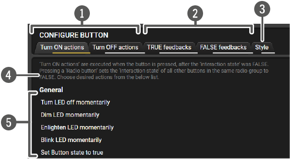
|
|
Tabs to set the action |
|
|
Tabs to set the feedback |
|
|
Tab to set the button Style |
|
|
Short description |
|
|
Action or condition list |
Summary of the actions and feedbacks tabs
|
Button operation mode |
Tab name |
Action |
Feedback (condition) |
|
Momentary |
Press actions |
Choose the desired action from the list |
Interaction state is true |
|
Release actions |
Choose the desired action from the list |
Interaction state is false |
|
|
TRUE feedbacks |
Interaction state is true |
Choose the desired condition from the list |
|
|
FALSE feedbacks |
Interaction state is false |
Choose the desired condition from the list |
|
|
Toggle |
Toggle ON actions |
Choose the desired action from the list |
Interaction state is true |
|
Toggle OFF actions |
Choose the desired action from the list |
Interaction state is false |
|
|
TRUE feedbacks |
Interaction state is true |
Choose the desired condition from the list |
|
|
FALSE feedbacks |
Interaction state is false |
Choose the desired condition from the list |
|
|
Radio group 1-5 |
Turn ON action |
Choose the desired action from the list |
Interaction state is true |
|
Turn OFF action |
Choose the desired action from the list |
Interaction state is false |
|
|
TRUE feedbacks |
Interaction state is true |
Choose the desired condition from the list |
|
|
FALSE feedbacks |
Interaction state is false |
Choose the desired condition from the list |
Button configuration steps:

Step 1.Choose the tab and click on the desired action or condition in the thematic list.
Step 2.Type the missing parameters (and the delay, if it is necessary) in the pop up window (on the right).
Step 3.Click OK to save. The configuration is saved as an Event in the Event Manager. It can be seen in the event list, numbered backwards.
Stylize the Buttons
When the button has a function, the last step is to add a text or icon to the wireframe view. This layout will appear on the Built-in Miniweb and supports the identification of the virtual buttons with the front panel.

|
|
Tab of Style config. |
|
|
Button icons (same with the device label stickers ). Click one to set for the currently selected button. |
|
|
Selected icon (highlighted with amber frame) |
|
|
Button text entry field. Maximum three rows can be displayed for one button. 30 ASCII characters are allowed for all rows. |
|
|
Click to clear the button style. |
|
|
Click to open the Miniweb page in the web browser. For more details, see the Built-in Miniweb section. |
|
|
This QR code contains the web address of the Miniweb page. It can be saved in png. |

TIPS AND TRICKS:Using the same appearance of the button with the label on the physical device helps identify them easily.

This section provides an overview of all defined events of the selected button. One line represents one event. It displays the delay time between the action and the condition, the condition or the action with the parameters, the event number, where the current setting is saved.
The  icon shows that the event was not created from the UI config page. It means that an event was set in the Event Manager, where the interaction state of the selected button was defined as an action or condition (e.g. /EVENTS/E3.Condition=/MANAGEMENT/UI/BUTTONS/BUTTON11.State=true )
Click on the icon to Show advanced expression. It displays the LW3 path of the event.
TIPS AND TRICKS:If the Show advanced expression mode is not active, keep the cursor on the event line for a second, and the whole expression appears in the hint box.
The following settings are available in this section:
▪The existing events can be edited by clicking on the event line (when it is highlighted with amber). Modifying the event properties is possible in the pop-up window.
▪Click on the icon beside the event to delete it.
▪All events of the button can be copied to another button. Choose a target button by clicking on the drop-down menu and select the Copy to option.
▪All events of the button can be swapped with another button. Choose a target button by clicking on the drop-down menu and select the Swap with option.
▪Clear All button is for deleting all events of the selected button.
5.4.3. Configurations of the Rotary
Click the rotary icon on the wireframe view to display and modify the related configuration.
The jog dial knob can be configured for volume control (or other controlling purposes). Turning left and right the rotary triggers the command sending via RS-232 or Ethernet.
Mute and unmute commands are assigned to the knob press, level 0-16 commands belong to the volume setting on a 16-level scale.

Follow the instructions to set the rotary:
Step 1.Choose an interface for the (volume) command sending (via RS-232 port or via Ethernet port). When the Ethernet is selected, IP address and port number are also required.
Step 2.Choose a volume control schema: Custom or Lightware.
a)Custom schema makes it possible to send serial or Ethernet messages to the third-party (or Lightware) device depending on the rotary state. Type the desired commands into the proper entry fields.
b)Lightware schema is for controlling the volume of the analog audio levels of the chosen audio port in any Lightware device. The entry fields are inactive, because the command schema is loaded automatically after setting the parameters:
▪The target device can be selected by typing the device type or chosen from the device list/generic schema list in a drop-down menu. For more details about the generic schema see Volume Control Schema Table
▪Write the audio port number (e.g. I2 or O8)
▪Click Set to confirm. Commands are loaded into the list.
▪The Send unmute when volume changed option allows setting the volume while the controlled device is in muted state. If the option is enabled, the unmute command is sent, the LED is switched off and the volume setting command is sent. If the option is unchecked, only the volume setting is processed.
▪Save the Schema by clicking Save Configuration to Device button. The configuration is saved to Events in the Event Manager (one event for one level settings). It can be seen in the event list, numbered backwards.
Step 3.Rotary LEDs give feedback about the current position of the jog dial knob. As it is rotated right (and the volume increases), the LEDs turn on one-by-one. One level means half brightness.
Generic schemes collects the Lightware devices by the same audio setting commands.
|
Schema ID |
Device Type |
|
Generic LWR-A |
DP-TPS-TX220 DVI-HDCP-TPS-TX220 FP-UMX-TPS-TX120, TX130 HDMI-3D-OPT-RX150RA HDMI-3D-OPT-TX220 HDMI-TPS-RX110AY HDMI-TPS-TX220 MMX4x2-HDMI MMX4x2-HT200 SW4-OPT-TX240 SW4-TPS-TX240 UMX-TPS-TX120, -TX130, -TX140 WP-UMX-TPS-TX120, -TX130 |
|
Generic LWR-B |
MX2-16x16-DH-8DPi-A-R, MX2-24x24-DH-12DPi-A-R MX2-24x24-DH-24DPio-A-R, MX2-24x24-HDMI20-Audio MX2-24x24-HDMI20-Audio-R, MX2-32x32-DH-16DPi-A-R MX2-32x32-HDMI20-A-R, MX2-48x48-DH-24DPio-A-R MX2-48x48-DH-48DPio-A-R, MX2-48x48-HDMI20-A-R MX2-8x4-HDMI20-CA, MX2-8x8-DH-4DPi-A MX2-8x8-DH-8DPi-A, MX2-8x8-DH-8DPio-A MX2-8x8-HDMI20-Audio, MX2-8x8-HDMI20-Audio-L MX2-8x8-HDMI20-CA |
|
Generic LWR-C |
MMX8x4-HT420M (mixer addon) MMX8x4-HT400MC (mixer addon) |
|
Generic LWR-D |
MMX6X2-HT200 MMX6X2-HT210 MMX6X2-HT220 |
|
Generic LWR-E |
MX-FR (IB/OB-A) UMX-OPT-TX150R UMX-TP-TX100 |
|
Generic LWR-F |
UBEX-PRO20-HDMI-F110, -F120 |
|
Generic LWR-G |
VINX-120AP-HDMI-ENC VINX-120AP-HDMI-ENC-DNT VINX-210AP-HDMI-ENC VINX-110AP-HDMI-DEC |
5.5. Control Menu

RS-232 Tab in Control Menu
The following settings and functions are available (both on local and TPS serial ports):
▪Operation mode: Control, Command Injection, or Disconnected (for more details about serial interface modes see the Serial Interface section);
▪Baud rate: 4800, 7200, 9600, 14400, 19200, 38400, 57600, 115200;
▪Data bits: 8 or 9;
▪Parity: None, Odd, or Even;
▪Stop bits: 1, 1.5, or 2;
▪Command injection: enable or disable; port number; #commandinjection
▪Control protocol: LW2 or LW3; #protocol #rs232 #rs-232 #serial
▪Message sending via serial port; #message
▪Reloading factory defaults (see factory default settings in the Factory Default Settings section).
RS-232 Message Sending

The message in the field can be sent out via the current RS-232 port. Response cannot be seen in the surface.
ATTENTION!The escaping is done automatically when sending a message via this surface. When the message is an LW3 command, it has to be closed by Carriage return and Line feed, e.g.: CALL /MEDIA/VIDEO/XP:switch(I1:O1)\x0d\x0a.

This tool can be used to recognize messages coming from the RS-232 port. The message can be used as a Condition in Event manager and define an Action for it.
Definitions #message
Delimiter sequence (hex): Each message is closed by this separator (if defined).
Accept timeout (ms): When the set time is elapsed after the last received message and delimiter was not detected, the device saves the data into the Text, Hex, and Hash properties. The timeout setting is useful if there is no special or easily defined delimiter in the incoming data, but there is a time gap between the messages.
Text: The recognized message in ASCII-format.
Hex: The recognized message in hex format.
Hash: Binary data that is mapped from the original message. The length of the hash is shorter, and the same message results the same hash.
Working Method
A message got recognized from the incoming data, if one of the following occurs:
▪The set DelimiterHex is detected in the message, or
▪The set TimeOut has been elapsed since receiving the last data bit.

GPIO tab in Control menu
The GPIO port has 3 pins, which operate at TTL digital signal levels and can be controlled by LDC or protocol commands. Select a GPIO pin and under the Port settings section; the settings (pin direction and input level) are displayed on the port tiles as well:

* Highlighted with black means the current setting.
INFO:Output level can be set only in case of setting the pin direction to Output. In case of input direction the output level setting and the Toggle button is not available.
Ethernet Ports
Two ports are displayed in the Ethernet settings: PoE in Eth and PoE out Eth. You can check the status of the Ethernet line by each ports: the speed and the duplexity of the connection.
The following settings are available for each ports:
▪Enable / disable the port,
▪Reload the factory defaults.
The PoE feature can be enabled/disabled on PoE out Ethernet port.

Ports tab in the Control/Ethernet menu
HTTP Clients (HTTP Post and Put Message Sending)
ATTENTION!This feature means posting or putting HTTP messages from the Lightware device to another device. Encrypted transmission (HTTPS) is not supported.
The HTTP Clients tab allows sending HTTP post and put messages to the desired server IP:port no. Control commands can be set to the target device, but it is not suitable for processing the response (e.g. querying a parameter/status. #http
The feature is available also by LW3 commands, see the HTTP Messaging section.

HTTP Clients tab in the Control/Ethernet men
When you press the enter in the Http header or Http body text box, the \r\n is added automatically.
TCP Clients (TCP Message Recognizer)
This tab is for the preparation and monitoring interface for the TCP recognizer feature. The incoming TCP messages can be detected which may trigger Event Manager Actions. A simple example can be seen in the TCP Recognizer section. #tcprecognizer #message

TCP Clients tab in the Control/Ethernet menu
The target device has to be set as a TCP client (three clients can be set):
Step 1.Type and set the Target IP address.
Step 2.Type and set the TCP port number.
Step 3.Make sure the same TCP port is opened and Enabled in the target device.
Step 4.Press the Connect to target button.
Step 5.Make the target device send a message and check it in the Detected messages list.
▪Auto reconnect: Numeric value; sets the time (seconds) between the automatic reconnections.
▪Delimiter: When the delimiter hex string is detected in the incoming data, the message is saved from the first bit until the delimiter (or the data between the two delimiters).
▪Timeout: If there is no response within the set time interval (milliseconds), the data will be accepted, that is received from the last delimiter.
▪Trigger Action: If data is received that is closed with the recognized delimiter, an Action can be run. Type the number of the Event (without letter 'E').
SalvoHttp Status Page (Receiving HTTP Message)
ATTENTION!This feature means sending HTTP messages from an external device to the Lightware device. Encrypted transmission (HTTPS) is not supported.
In this case, a batch of commands can be sent over HTTP to the Lightware device for processing. Post the commands to the <IP_address>/protocol.lw3 address and the commands are processed immediately and sequentially. #http
Control commands can be sent to the Lightware device, but it is not suitable for querying a parameter/status since the LW3 responses are not sent back to the sender.
ATTENTION!If the Cleartext Login (Login Settings) is enabled in the device, the login has to be the first command. No commands will be processed without a successful login. See the syntax in the Login the Device section.

SalvoHttp tab in the Control/Ethernet menu
Infra-Red (IR) receiver options can be found on this tab. There are three submenus are available under it:
IR codes, Ports, and Clear all IR codes.
IR Codes
The user can set the name of the IR code, the fingerprint (hash), and the repeat timeout in ms, actions can be ordered to each IR code as well.
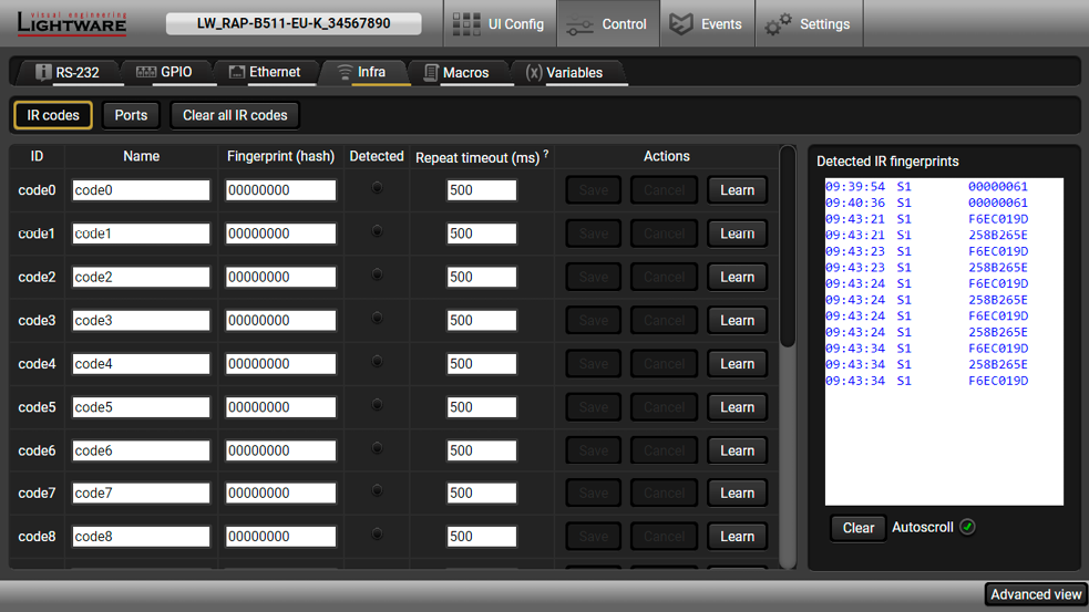
IR Codes Window in the Control Menu
|
Description |
Function |
|
ID |
Code number. |
|
Name |
You can give an unique name for the desired code. |
|
Fingerprint (hash) |
Fingerprint code in pronto hexa format. |
|
Detected |
Indicator gives feedback about the given IR code is detected currently. |
|
Repeat timeout (ms) |
You can set a timeout to avoid the involuntary code recurrence. |
|
Actions |
Save: saving the fingerprint and/or the name of the IR code. |
|
Detected IR fingerprints |
The IR fingerprints are displayed in the box that can be emptied by the Clear button. |
20 fingerprints can be stored in the device at the same time. Each of them can be ordered to an action in Event Manager.
Step 1.Click on the Learn button.
Step 2.Turn the remote controller to the IR detector. A pop-up window appears in LDC - press your remote button to learn.
Step 3.Once the code is received, a new window pops up in LDC - learning completed. Click OK to continue.
Step 4.Optionally type a unique name for the code in the Name text box. The default name is code#, e.g. code0.
Clear all IR codes
Clicking on the button results deleting all stored IR fingerprints.
Ports Tab
User can set the name and command injection port to each sources and destinations. For more details about IR interface see the Infra Interface section.

Infra Tab - Ports Window
DEFINITION:Macro is a batch of pre-defined commands stored in the device. #macro
You can create your custom macros in a file, upload to the device and run at any time. This device can handle up to 50 macros.
Important Notes about Macros
▪The macros are stored in device presets.
▪The commands of a macro are executed sequentially (even if error happens at a command).
▪Macros allow long commands that is suitable for e.g. infra code sending.
▪Macros cannot be edited in the device.
▪Macros are not saved when backup is created. See the Saving the Macros section.
;<preset_name>
;Begin <macro1_name>
<LW3_commands>
;End <macro1_name>
;Begin <macro2_name>
<LW3_commands>
;End <macro2_name>
Format:
;myDeviceMacros
;Begin myMacro1
CALL /MEDIA/VIDEO/XP:unmuteSource(I3)
CALL /MEDIA/VIDEO/XP:switch(I3:O1;I3:O2)
;End myMacro1
;Begin myMacro2
CALL /MEDIA/VIDEO/XP:unmuteSource(I4)
CALL /MEDIA/VIDEO/XP:switch(I4:O1;I4:O2)
;End myMacro2
Example:
<preset_name>: it will be displayed in the Settings/Backup submenu (device configurations list).
<macro_name>: each macro must have a unique name.
<LW3_commands>: LW3 SET and CALL commands. Syntax is not checked, error is not reported.
ATTENTION!If you use the same name for a new macro, the existing one will be deleted.
Open a simple text editor and save the file with 'LW3' extension.
Uploading New Macros into a New Preset
The recommended way for macros is to use a Device configuration preset for this purpose exclusively. When you have to add new macros or change any of them, use the dedicated preset. The uploading steps are the following:
Step 1.Create the file with macros according to the macro file structure and save it.
Step 2.Navigate to the Settings/Backup submenu.
Step 3.Select a device configuration preset at the bottom of the page.
Step 4.Press the Upload button, browse the LW3 file and press Open.
ATTENTION!The preset and the macros of the selected slot will be erased. If there is a macro with the same name already in the device, it will be removed and the new one will be available.

Discovered Macros in the device shown under Control/Macros submenu
Adding Macros to an Existing Preset
Step 1.Navigate to the Settings/Backup submenu.
Step 2.Select a device configuration preset at the bottom of the page.
Step 3.Press the Download button and click Save in the pop-up window.
Step 4.Open the file with a simple text editor and add the desired macros to the bottom of the commands between the ;Begin <macro_name> and ;End <macro_name> labels.
Step 5.Save the file and navigate to the Settings/Backup submenu.
Step 6.Select the same device configuration preset as selected in Step 2.
Step 7.Press the Upload button, browse the LW3 file and press Open.
If you follow above steps, the existing macros of the selected preset will be preserved. But if there is a macro with the same name already in the device, it will be removed and the new will be available.
When you make a backup of the device, the macros are not saved in that file. Sometimes, it is necessary to save the macros into a file and for example apply them in another (same type of) device. Follow these steps:
Step 1.Navigate to the Settings/Backup submenu.
Step 2.Select the device configuration preset that is used for the macros at the bottom of the page.
Step 3.Press the Download button and click Save in the pop-up window.
A brand new area is opened by implementing the variables. You can create custom variables in number or text format which can be used in the Event Manager. The variables can have the following properties/methods: #variables
▪Numeric (integer) type with min/max value setting, or string-type (determined automatically)
▪Increment/step the numeric value,
▪Value-dependent case operations,
▪Reading and storing the values of LW3 properties into string or numeric variables.
▪The max length of a string variable can be 15 characters. Numeric variable is defined between -2147483648 and 2147483647.
The defined variables are stored in a non-volatile memory and the value is kept in case of a reboot.

Variables tab in the Control menu
Value Section
You can set the value of the variable by the field. The type of the variable is determined automatically based on its value (numeric/string).
Add / Cycle Section
This section can be used for numeric types.
▪Operand: the increment, the number that will be added to the current value (negative value is accepted).
▪Min (optional): the lowest allowed value.
▪Max (optional): the highest allowed value.
▪Add button: the operand will be added to the current value. If the result would be higher than the max setting, the max will be valid; if the result would be lower than the min setting, the min will be valid.
▪Cycle button: the operand will be added to the current value. If the result would be beyond the limit (min/max), the value will be stepped to the other end of the interval.
Examples
The following shows the difference between the Add and the Cycle options. The input values are the same in both cases:


▪Min: 1
▪Max: 5
▪Operand: 1
In Add case: when the value hits the limit (max), the operand will not increase the value any more.
In Cycle case: when the value hits the limit (max), the value will be stepped to the other end of the interval.
Similar case happens vice versa: when the operand is a negative number and the value hits the min value.
TIPS AND TRICKS:Set min=1, max=2, operand=1 and use the cycle method. Thus, the value of the variable can be toggled which can be linked to a property with two states (e.g. low/high level) in Event manager.
Case Convert
This tool can be used to change the value of a variable if it fits in any of the defined intervals. The check and the change will be performed only if you press the Convert button. A typical example when two different ranges of values have to meet:
Incoming values: between 0 and 255 (e.g. the slider of a controller can have these values).
Outgoing values: between 0 and 100 (e.g. the controlled device accepts these values).
Defined cases:
|
Min |
Max |
New value |
|
|
Case 1 |
1 |
25 |
10 |
|
Case 2 |
26 |
50 |
20 |
|
Case 3 |
51 |
75 |
30 |
|
Case 4 |
76 |
100 |
40 |
|
Case 5 |
101 |
125 |
50 |
|
Case 6 |
126 |
150 |
60 |
|
Case 7 |
151 |
175 |
70 |
|
Case 8 |
176 |
200 |
80 |
|
Case 9 |
201 |
225 |
90 |
|
Case 10 |
226 |
255 |
100 |
Scan and Store
This tool can be used to get the value (or a part) of an LW3 property. The defined path will be checked according to the pattern and the result will be saved into the variable (number or string type). Press the ? button to open the pattern options:
|
Pattern |
Pattern description |
|
%s |
String of characters stopping at the first whitespace character |
|
%<number>s |
The next <number> of characters (string) stopping at the first whitespace |
|
%c |
One character |
|
%<number>c |
The next <number> of characters |
|
%[<characters>] |
Defined character set, specified between brackets |
|
%[^<characters>] |
Negated character set, specified between brackets which will be skipped |
|
%* |
Ignored part |
|
<custom_text> |
User-defined text |
Examples
Scanned property: /MANAGEMENT/STATUS.CpuTemperature=46 C; 0;75; 0;79; 3;48;
|
<pattern> |
Scan result |
Variable type |
Comment |
|
%s |
46 |
Number |
Scanned from the first character till the first whitespace character |
|
%5c |
46 C; |
String |
The first 5 characters scanned |
|
%*18c%4c |
3;48 |
String |
The first 18 characters skipped then 4 characters scanned |
|
%*s %c |
C |
String |
The first part till the first whitespace character (and the space) are skipped then 1 character scanned |
|
%*[^;]; %4c |
0;75 |
String |
From the first character till the first semicolon and a space are skipped, then 4 characters scanned |
|
%*[^;]; %*[^;]; %*[^;]; %4c |
0;79 |
String |
Three groups ended with semicolon and space are skipped then 4 characters scanned |
Reformat
The value of the variable can be changed by adding text as prefix and/or postfix. Type %s to indicate where to insert the original value.
Example
▪Original value: 3
▪Pattern: input%s
▪Modified value: input3
The feature means that the device can sense changes on its ports and able to react according to the pre-defined settings. The development idea of the Event manager is based on users’ feedbacks. In many cases internal events are necessary to display but it is not easy when the device is hard to access (e.g. built under the desk).
The Event manager can be configured to perform an action if a condition has been detected. E.g. the desired setup is that after a certain type of IR signal has been detected on S1 port, the device send an RS-232 message. The settings can be done via the LDC in the main menu, or by LW3 protocol commands. Configurable events number depends on the device what you are using actually.
Numerous new ideas and requests have been received in connection with the features and settings of the Event manager since the first release. Therefore, the user interface has been re-designed and many new functions implemented. The Event editor can be opened by pressing the Edit button at each Event.
There is a grey bar on the left of the Event panel in each line. If a condition and an action are set and the Event is enabled, the bar is displayed in green.
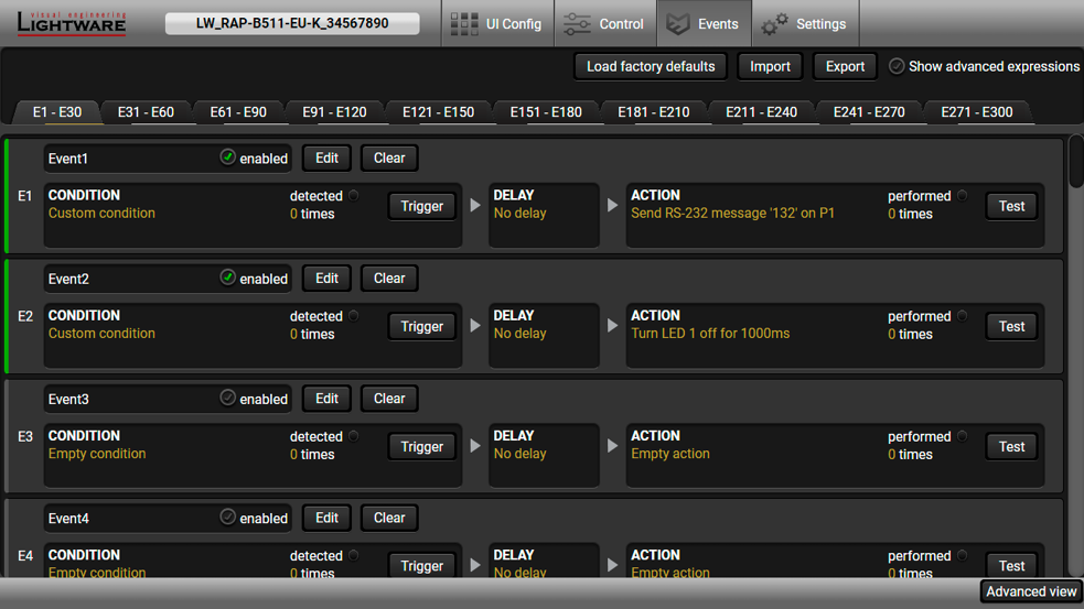
Control menu, Event Manager tab
#eventmanager
5.6.1. Event Manager in the RAP-B511 series
The functionality of the Room Automation Panel is based on the Event Manager. UI config page provides an interface where the events can be set easily and they are saved in the Event Manager. Events from the UI config page are listed backwards (e.g. first event is saved to the E300 slot).
These events are identified by the event name property, which refers to the button (e.g. UIConfig_B11_1) or the rotary position (e.g. UIConfig_ROT_13).
ATTENTION!Rename the Events from the UI Config page is highly not recommended!
When one of these events is opened to Edit in the Event Manager, the warning message appears:

The tables below summarize the availablility of the conditions and actions of the RAP-B511.
Conditions
|
Launch configuration from... |
...UI config menu |
...Event Manager |
|
Button press /button release |
|
|
|
Rotary turn / rotary press |
|
|
|
Real-time clock |
|
|
|
Infra detector |
|
|
|
RS-232 recognizer |
|
|
|
GPIO input level change |
|
|
Actions
|
Launch configuration from... |
...UI config menu |
...Event Manager |
|
Button LEDs |
|
|
|
Button Interaction State |
read-only |
|
|
Ethernet |
|
|
|
RS-232 |
|
|
|
GPIO |
|
|
The setting is available and recommended to do the configuration from this menu.
The setting is not available in that menu.
Only for advanced users! The setting is available in the Event Manager, but doing the configuration is highly recommended from the UI config menu.
5.6.2. The Event Editor
Press the Edit button in the desired Event line to open the Event editor window.

|
|
Event header |
The name of the Event is displayed. Type the desired name and press the Set name button. The Event can be cleared by the Clear button. Use the tick mark to enable/disable the Event. |
|
|
Condition header |
If the condition is set, the description (white colored text) and the exact LW3 protocol expression (yellow colored text) can be seen. If the advanced mode was used the description is Custom condition. |
|
|
Condition panel |
The Wizard, the Advanced or the Link tool is available to set the condition. The parameters and settings are displayed below the buttons. |
|
|
Condition test |
The set condition can be tested to see the working method in the practice. |
|
|
Delay settings |
The action can be scheduled to follow the condition after the set time value. |
|
|
Action header |
If the action is set, the description (white colored text) and the exact LW3 protocol expression (yellow colored text) can be seen. If the advanced mode was used the description is Custom action. |
|
|
Action panel |
The Wizard, the Advanced or the Link tool is available to set the action. The parameters and settings are displayed below the buttons. |
|
|
Action test |
The set action can be tested to see the working method in the practice. |


5.6.3. Create or Modify an Event
Wizard Mode

The wizard mode lists the most common conditions and actions, so the user does not have to look for LW3 nodes and properties.
Step 1.Click on the Edit button of the desired Event; the Event editor is displayed.
Step 2.The wizard mode is displayed as default. Select the desired Category first (e.g. Audio or Video).
Step 3.Select the desired Expression from the drop-down menu. If any other parameter is necessary to set, it is going to be displayed.
Step 4.Press the Apply button to store the settings of the Condition.
INFO:This mode is also available for setting the Action.
Advanced Mode
The goal of this mode is the same as of the wizard: set the properties and methods for conditions and actions. The difference is the number of the available and usable properties and methods of the LW3 protocol. Advanced mode allows almost all of it.

Step 1.Click on the Edit button of the desired Event; the Event editor is displayed.
Step 2.The wizard mode is the default, press the Advanced button. The LW3 protocol tree is displayed showing the list of the properties in the drop-down menu. Navigate to the desired node.
Step 3.Select the desired Property from the menu. The manual of the property is displayed below to help to select the necessary property and to set the value.
Step 4.Set the desired value and operator, then press the Apply button to store settings.
INFO:This mode is also available for setting the Action.
The Link Tool

The new interface allows creating more actions for the same condition. In that case, a condition can trigger more actions. To set such an Event, the Link tool has been introduced.
Step 1.Click on the Edit button of the desired Event; the Event editor is displayed.
Step 2.The wizard mode is displayed as default, press the Link button.
Step 3.All the saved Events are analyzed and the conditions are listed (it takes some seconds to finish). The Show advanced expressions option allows showing the exact path and set the value of the given property.
Step 4.Select the desired Condition and press the Apply button to store the settings.
INFO:This mode is also available for setting the Action.

DIFFERENCE:This feature is available from FW package v1.1.0b3.
The first generation of the Event Manager is able to sense a change (one condition) but in some cases that is not enough. The practical experience has shown there is a need to examine more conditions as follows: if one of the set conditions becomes true (while the other conditions are fulfilled), then the set Action is launched. The Combine Links tool allows setting these Conditions. Follow the steps below:
Step 1.Create individual Conditions in separate Events.
Step 2.Create a new Event and navigate to the Combine Links tab in the Editor.
Step 3.Select up to four Conditions in the left panel.
Step 4.Set the desired Action (and do not forget to enable the Events).
INFO:This mode is available for setting the Condition only.
Linking a Macro (Action)

DIFFERENCE:This feature is available from FW package v1.1.0b3.
Macros stored in the device can be run as Actions. Thus, a lot of commands can be run by using only one Event. The commands will be processed one-by-one after each other. #macro
Step 1.Click on the Edit button of the desired Event; the Event editor is displayed.
Step 2.The wizard mode is the default, press the Macros button in the Action panel.
Step 3.Select the desired Macro from the list then press the Apply button to store settings.
If the Use variables option is enabled, you can link a variable by the $ character. If you do so (e.g. $1), the device will handle it as the V1 variable. You can send the value of the variable e.g. as a TCP message.
See more information about the Macro settings in the Macros section.
5.6.4. Special Tools and Accessories
The Name of the Event
The name of a port can be changed by typing the new name and clicking the Set button. The following characters are allowed when naming:
Letters (A-Z) and (a-z), numbers (0-9), special characters: hyphen ( - ), underscore ( _ ), and space ( ).
Enable or Disable an Event
The set Event can be enabled or disabled in the Event list, or directly in the Event editor window by setting the tick mark beside the name.
Testing the Condition
When the desired Condition is arranged, the setting can be tested. The Event list and the Event editor contains a small panel that shows if the set condition is detected and how many times. The Counter can be reset by the button in Event editor. If the Condition is true, the detected mark turns green for two seconds and the Counter is increased.
Testing the Action
The method is the same as testing the Condition, but in this case, the Action can be triggered manually by pressing the Test button.
TIPS AND TRICKS:The Test button is also placed on the Action panel in the Event list. Thus, you can check the Actions without opening the Event editor.
Delay the Action
In most cases the Action is performed immediately after the Condition is detected. But sometimes a delay is necessary between the Condition and the Action. Therefore, the new Event manager contains the Delay panel which allows that feature with below settings:
▪No delay: when the Condition is detected, the Action is launched.
▪Simple delay: when the Condition is detected, the Action is launched after the set time interval.
▪Still true after: when the Condition is detected, the Action is launched after the set time interval only if the Condition still exists.
▪Continuously true: when the Condition is detected, the Action is launched after the set time interval only if the Condition has been existing continuously.

The available delay settings of an Event
TIPS AND TRICKS:Show advanced expressions option is a useful tool when you look for the path or value of a property but just the expression is displayed. The option is available in the Event list window or when Link tool is used.
Variables
DIFFERENCE:This feature is available from FW package v1.1.0b3.
The variables and the tools (shown in the Control/Variables tab) can be used in the Event Manager.
Condition Wizard #variables
The desired variable can be checked if its value is changed to a specific value.
Action Wizard
The value of a variable can be set/changed by the same methods as in the Control/Variables tab:
▪Setting the exact value
▪Increasing the value with/without limits
▪Converting the value (e.g. interval change)
▪Scanning and storing, or reformatting a property/parameter
If the Use variables option is enabled, you can link a variable by the $ character. If you do so (e.g. $1), the device will handle it as the V1 variable. You can send the value of the variable e.g. as a TCP message.


DIFFERENCE:This feature is avail-able from FW package v1.1.0b3.
This improvement works as if a condition is detected. When a complex control system is built, a Condition may trigger numerous Actions. A typical example is when a system is powered on and the ’ready-to-use’ state has to be loaded. In this case, there could be many actions which are based on the same condition. In order to reduce the number of the commands, you can trigger one ’key’ condition, which could start the whole process.
5.6.5. Clear One or More Event(s)
Clear an Event
Press the Clear button in the Event list or in the header section in the Event editor.
Clear all Events
When all the Events must be cleared press the Load factory defaults button above the Event list. You will be prompted to confirm the process.
WARNING!Clicking on Load factory defaults button means, the configuration of the buttons are also deleted, because the conditions and the actions of the buttons are saved as events.
5.6.6. Export and Import Events
The feature allows saving all the Events. The backup file can be uploaded to another RAP-B511 series device.
Export all the Events
Step 1.Press the Export button above the Event list.
Step 2.The Save as dialog box will appear. Set the desired folder and file name, then press the Save button.
The generated file is a simple text file which contains LW3 protocol commands. The file can be viewed by a simple text editor, e.g. Notepad.
ATTENTION!Editing the file is recommended only for expert users.
Import all the Events
Step 1.Press the Import button above the Event list.
Step 2.The Open dialog box will appear. Select the desired folder and file, then press the Open button.

Status Tab in Settings Menu
The most important hardware and software related information can be found on this tab: hardware and firmware version, serial numbers, temperatures, operation time, and voltage information. Device label can be changed to unique description by the Set button.
Enable Lock buttons disables the whole functionality of the front panel (buttons and the rotary). Blinking of the button and rotary LEDs three times means, that the front panel functionality is locked. Unlocking is also possible via LW3 protocol commands (for more details see LW3 Programmers’ Reference section).
For more details about the Miniweb see Built-in Miniweb section.
#devicelabel #label #producttype #firmwareversion #identifyme #status #serialnumber
5.7.2. Network
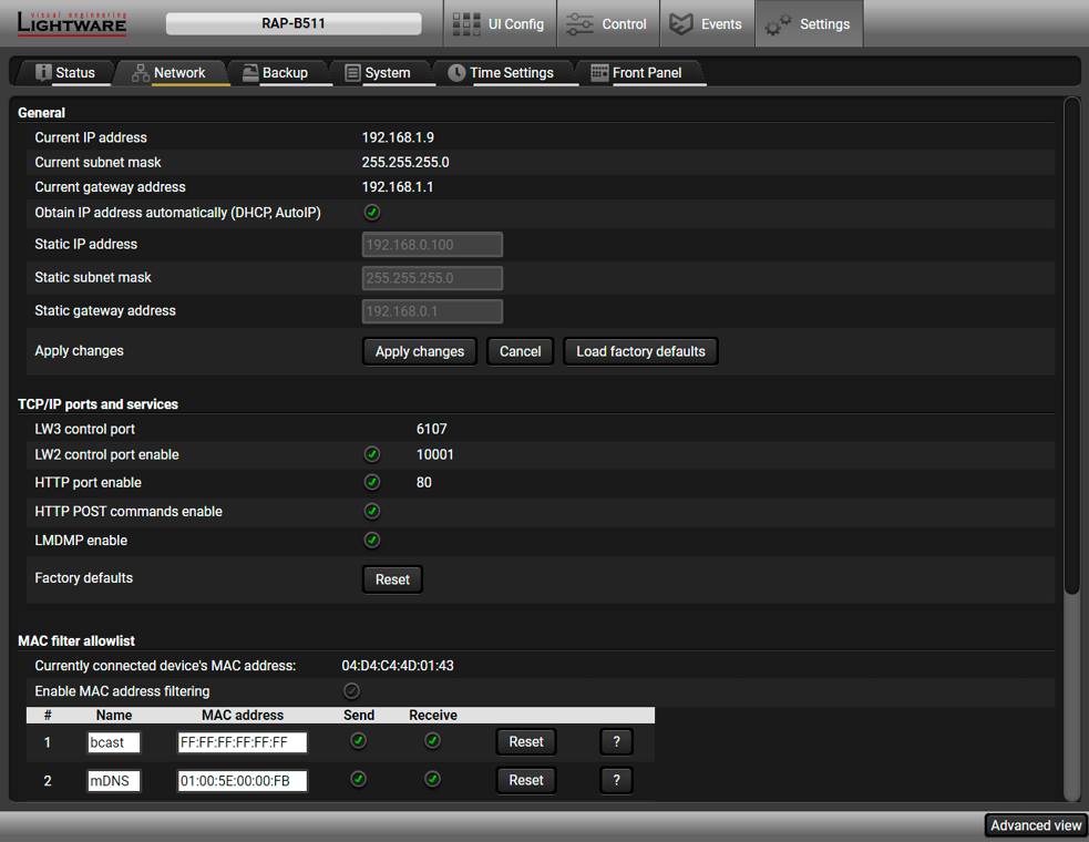
Network tab in Settings menu
General
IP address and DHCP settings can be set on this tab. Always press the Apply settings button to save changes. Factory Default Settings can be recalled with a dedicated button.
TCP/IP Ports and Services
DIFFERENCE:This feature is available from FW package v1.1.0b3.
The IP Port Block option is an additional protection for the Cleartext Login (Login Settings) feature. There are TCP/IP ports in Lightware devices which are not protected by the login, so you can disable them if necessary. For example, due to the working method of the LW2 communication, the Cleartext login does not provide protection when LW2 command is sent to the device, that is why the TCP port no.10001 shall be blocked manually. #dhcp #ipaddress #network #portblock
DIFFERENCE:This feature is available from FW package v1.1.0b3.
Another level of the security is the MAC Filtering tool. You can create a list of network devices based on the MAC address which are allowed: #macfilter
▪Controlling the device (Send option), or
▪Querying parameters (Receive option) to/from the Lightware device.
Do not forget to press the Apply changes button to store the new settings.
ATTENTION!The first three lines are factory default values and they are necessary for the proper working.
5.7.3. Backup
Details about this function can be found in the Configuration Cloning (Backup Tab) section.
5.7.4. System

System tab in Settings menu
Cleartext Login (Login Settings)
DIFFERENCE:This feature is available from FW package v1.1.0b3.
This cleartext login tool allows setting a password for login, thus, the device will not accept any command coming from a control interface (RS-232, Ethernet, etc…) without login. The device will be visible in the Device Discovery window (as the device type and the serial number can be queried without login) but connection can be established only after successful login. The login is valid until a TCP socket break in case of Ethernet connection. #login
ATTENTION!If the login is enabled, the password will be asked when the Built-in Miniweb is opened.
INFO:The login password is erased and the login is disabled when restoring the factory default values.
Further functions
▪Download system log - saving the file of the device.
▪Load factory defaults - recalling factory defaults settings and values. All factory default settings are listed in the Factory Default Settings section.
▪Reboot - rebooting the system. #factory #log #systemlog #reboot #restart
Real-Time settings can be managed from Time settings tab. For more details about the dependency of the time properties, see the Flowchart of the real-time clock configuration process.

Real time clock setting
In this section the current RTC (Real-time clock) time is displayed and can be modified manually. Click to Set button to save the new setting.
Set time zone setting
▪Time zone can be selected from the drop-down menu.
▪Check Enable the daylight saving if it is needed, and set the start and end date. These setting will added to the UTC (Universal Time Coordinated) and the NTP (Network Time Protocol) time.
INFO:If the RTC time is set manually, these settings will be ignored.
Set NTP (Network Time Protocol) settings
▪Enable NTP makes it possible to query time information from an NTP server. It means, that the RAP-B511 is permitted to get time information from an NTP server. The device time synchronized repeatedly and automatically. In this case, the NTP server address entry field is active, where the IP address or URL of the NTP server can be typed manually. Click to set to save the address. The current setting is also displayed.
▪Enable GET NTP from DHCP server means, when that DHCP server assigns an IP address to the device, its own IP address or URL can be queried, and this address may be saved as an NTP server. In this case, the user does not have to give the IP address or URL manually.
INFO:If the RAP/RAC device receives an answer including a DHCP option (e.g. Option 42, which is listed the addresses of the NTP servers), the saved NTP server will be the address based on the option, otherwise the NTP server from the device will be set.
▪Clicking on the Synchronize now button queries the time information from the NTP server. Time is updated, when the device is restarted, powered off and on again and in certain time periods.
▪For more information about the time properties, the see the Real-Time Clock in the Device Concept chapter.
All settings are available with LW3 protocol commands, see the details in Time Settings section in LW3 programmers reference chapter.
The following settings are available on the Front Panel tab:

▪Default low brightness and default high brightness intensity can be customized in 0-5 level scale where 0 means the no light, 5 means the maximum intensity.
The factory default value of the low brightness: 2
The factory default value of the high brightness: 5
▪You can disable the functionality of the front panel buttons and the rotary knob with marking the Lock buttons option.
▪Clicking on Identify the device button results the front panel LEDs blink for 10 seconds which helps to identify the device physically.
Built-in Miniweb feature supports to reach certain functions of the RAP-B511 in the web browser.
The RAP-B511 has three different type miniweb pages for different purposes: #miniweb #builtinweb
▪Default miniweb page: This interface provides similar functionality to the front panel.
▪Advanced Miniweb Page: Action trigger buttons of the selected events are displayed on this page.
▪Custom Miniweb page: Any .html site with custom content can be upload to the device.
▪General system requirements
▪System requirements for operating systems: Microsoft Windows XP, Windows Vista, Windows 7, Windows 10, macOS, Linux.
▪Compatible web browsers: Mozilla Firefox, Google Chrome, Apple Safari.
Lightware system requirements
▪Firmware package: the Miniweb is available from firmware package v1.0.3. The default control page can be installed in the device during the first firmware update process if the necessary parameter is enabled. See The Updating Steps section.
▪Lightware Device Controller software supports the Miniweb feature above v1.33.
▪Please be sure that the computer is in the same network as the RAP-B511. If the computer has multiple Ethernet connections (for example Wi-Fi and LAN connections are used simultaneously) you will have to know the IP address for the one that is used for controlling the automation panel.

This interface provides similar functionality to the front panel. Clicking on the button icon has the same effect as the buttonpress (or clicking on the Test Button Press button in the LDC). The volume control is available with the scrollbar. Button styles help to identify the buttons.
INFO:Button configuration settings of the RAP-B511 are not available in the Built-in miniweb page, because it is designed for common usage.
To activate the Default Miniweb page click on the Upload default button in the Settings menu/ Status tab.
The website can be easily reached:

▪Write the IP address of the device in the search bar of the web browser.
▪Launch the LDC, connecting to the device, navigate to Settings/Status or UI Config/Style and pressing the View miniweb button.
▪In the UI Config/Style tab, the QR code of the web address of the miniweb page is available and it can be download in .png format and print or display where the RAP-B511 is needed to control.
To delete the Default Miniweb page click on the Clear button.
ATTENTION!If the Cleartext Login (Login Settings) function is enabled, the login password will be necessary to access the miniweb.
The Advanced Miniweb is available by opening the web browser with this address:
http://<device_IP_address>/index.html?admin
The action trigger buttons can be used to perform a configured Event Action without waiting for the condition to occur. This can be done remotely by a mobile device, too. The buttons of Action triggers section are linked to Actions of certain Events in the Event Manager.
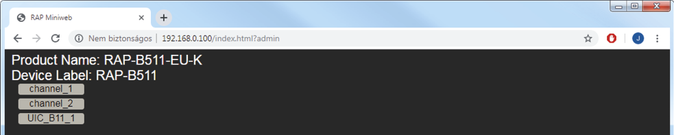
Advanced Miniweb Page
These buttons are displayed only for specific events:
▪Any Event which does not have the @W suffix in its name will not be displayed as a trigger button.
▪The displayed trigger buttons will get a text label with the event name except the suffix.
To add the desired Action as a button, append the name of the desired Event with the @W characters - see below (type uppercase for 'W' as it is case-sensitive):

The control page can be replaced in the LDC; navigate to the Settings/Status page. A custom HTML file can be uploaded by pressing the Choose file button. Pay attention to the size of the HTML file. Only one file is allowed and the maximum file size is 1024 KB. The default control page can be restored during a firmware update process, see The Updating Steps section.
Press the Clear button to remove the control page. In this case, status information becomes available about the device.

Miniweb Status Page
INFO:Status information is always available at http://<device_IP_address>/status.html page.
5.9. Configuration Cloning (Backup Tab)
The configuration cloning of Lightware LW3 devices is a simple method that eliminates the need to repeatedly configure certain devices to have identical (non-factory) settings. If the devices are installed in the same type of system multiple times then it is enough to set up only one device to fit the user’s needs and then copy those settings to the others, thus saving time and resources.
ATTENTION!Macros cannot be saved into the backup file. If you have macros stored in a Configuration slot, download it separately and upload it in the target device.
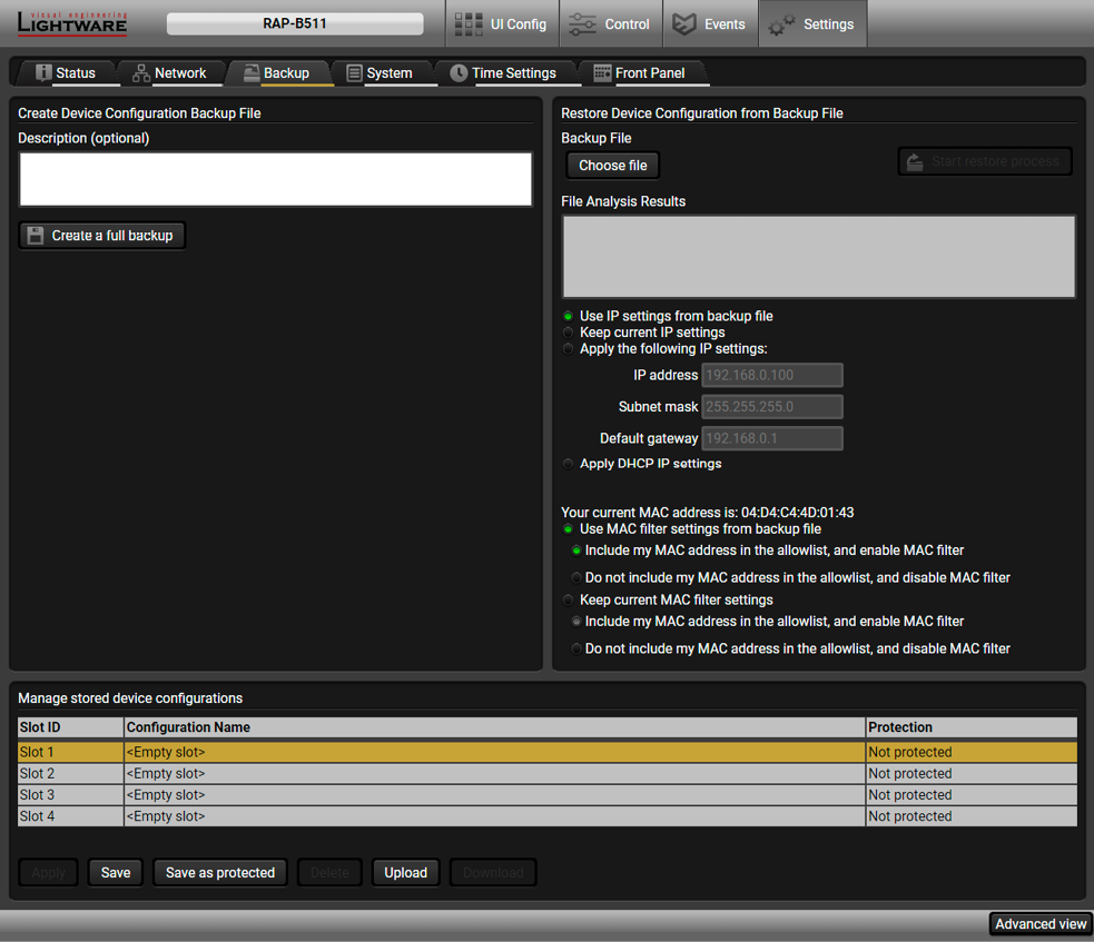
Backup tab in Settings menu
5.9.1. Cloning Steps in a Nutshell
Installing multiple devices with the same customized configuration settings can be done in a few easy steps:
Step 1.Configure one device with all your desired settings with the LDC software.
Step 2.Backup the full configuration file to your computer.
Step 3.If needed, make some modifications to the configuration file using a text editor (e.g. Notepad). E.g. modifying the static IP address is needed when DHCP is not used.
Step 4.Connect to the other device which has to be configured and upload (restore) your configuration file.
Step 5.Done! You can have as many totally identical, customized devices as you like.
5.9.2. Save the Settings of the Device (Backup)
ATTENTION!The Macros stored in the device will not be saved to the backup file.
Step 1.Apply the desired settings in the RAP-B511 (events, serial settings, etc.)
Step 2.Select the Settings / Backup tab from the menu.
Step 3.Write a short description in the text box on the left (optional).
Step 4.Press the Create a full backup button. You will be prompted to save the file to the computer. The default file name is the following:
backup_<DEVICE LABEL>_SN<SERIAL NUMBER>.LW3
Step 5.Set the desired file name, select the folder and save the file.
TIPS AND TRICKS:Using the exact product type in the filename is recommended since it makes the file usage more comfortable.
About the Backup File
The backup file is a simple text file which contains LW3 protocol commands. The first line is the description, and the further lines are the commands which will be executed during the restore process. The file can be viewed (and/or edited) by a simple text editor, e.g. Notepad.
ATTENTION!Editing the command lines is only recommended for expert users.
See the entire list of saved data in the Content of Backup File section.
5.9.3. Upload the Settings to a Device (Restore)
WARNING!Please note that the settings will be permanently overwritten with the restored parameters in the device. Withdrawal is not possible.
ATTENTION!The cloning is successful when the backup file is downloaded from the same type of source device as the destination device.
The Restoring Process
Step 1.Select the Settings / Backup tab from the menu.
Step 2.Click on the Choose file button on the right panel and browse the desired file.
Step 3.The file is checked and the result will be displayed in the textbox below. If the file is correct, the settings can be restored.
Step 4.Choose IP settings what you want to use after backup. You can apply settings from the backup file, keep actual settings, set it manually in a dialog box or apply DHCP.
Step 5.Select the desired MAC filter settings to be applied in the device. See more information about this feature in the MAC Filter Allowlist section.
Step 6.Press the Start restore process button and click on the Yes button when asked.
Step 7.Reboot the device to apply the network settings after finishing.
5.9.4. Create and Restore Backups from the Device Memory
The device can store configurations in its own memory, four slots are available for this purpose.

You can save the configuration to the desired slot:
▪without protection: it can be easily applied/deleted, or
▪with protection: it can be protected by a password to apply or delete the configuration.

|
Loading the selected configuration |

|
Deleting the selected configuration |

|
Saving the current configuration to the selected slot without protection |

|
Loading a configuration from a file to the selected slot |

|
Saving the current configuration to the selected slot with a password |

|
Saving the selected configuration as a file |
The presets can be used for the macros as well, please see the Macros section.
WARNING!Loading factory default settings will erase all presets in the device memory.

|
|
LW3 protocol help |
Pushing the button results a help window opening which describes the most important information about LW3 protocol commands in HTML format. |
|
|
|
Edit mode |
The default appearance is the read-only mode. If you want to modify the values or parameters, tick the option. You will be prompted to confirm your selection. |
|
|
|
Warning mode |
If this is checked, a warning window pops up when you enable Edit mode. |
|
|
|
Terminal window |
Commands and responses with time and date are listed in this window. Sent command starts with ‘>’ character, received response starts with ‘<’ character. The color of each item depends on the type of the command and response. The content of the window can be emptied by the Clear button. If the Autoscroll option is ticked, the list is scrolled automatically when a new line is added. |
|
|
|
Command line |
Type the desired command and execute it by the Send button. Clear all current commands and responses in the Terminal window by the Clear button. The commands typed in this line are not escaped automatically. See more information in the Escaping section. |
|
|
|
Protocol tree |
LW3 protocol tree; select an item to see its content. |
|
|
|
Node list |
Correspondent parameters and nodes are shown which are connected to the selected item in the protocol tree. The commands typed in these fields are escaped automatically. |
|
|
Manual button: |
Manual (short description) of the node can be called and displayed in the terminal window. |
||
|
Set button: |
Saves the value/parameter typed in the textbox. |
||
|
Call button: |
Calls the method, e.g. reloads factory default settings. |
||
The device can be controlled through a reduced command set of LW2 protocol commands to ensure the compatibility with other Lightware products. The supported LW2 commands are described in this chapter.
6.1. Protocol Description
The protocol description hereinafter stands for Lightware protocol. The commands can be sent to the device in RAW format via the TCP/IP port no. 10001.
The receiver accepts commands surrounded by curly brackets - { } - and responds data surrounded by round brackets - ( ) - only if a command was successfully executed. All input commands are converted to uppercase, but respond commands can contain upper and lower case letters as well.
Legend for Control Commands
|
Format |
Explanation |
|
<in> |
Input number in 1 or 2 digit ASCII format (01, 5, 07, 16, etc.) |
|
<out> |
Output number in 1 or 2 digit ASCII format |
|
<in/out> |
input or output port number in 1 or 2 digit ASCII format * |
|
<in2> |
Input number in 2 digit ASCII format (01, 02, 10, 12 etc.) |
|
<out2> |
Output number in 2 digit ASCII format (01, 02, 10, 12 etc.) |
|
<in2/out2> |
input or output number in 2 digit ASCII format* |
|
<loc> |
Location number in 1, 2 or 3 digit ASCII format |
|
<id> |
id number in 1 or 2 digit ASCII format |
|
<id2> |
id number in 2 digit ASCII format |
|
CrLf |
Carriage return, Line feed (0x0D, 0x0A) |
|
· |
Space character (0x20) |
|
→ |
Each command issued by the controller |
|
|
Each response received from the router |
* The command has the same arguments on the input ports and the output port, as well.
6.2. Instructions for the Terminal Application Usage
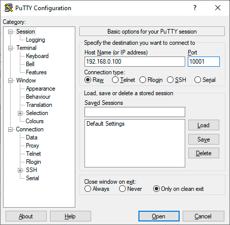
Terminal Application
The LW2 protocol commands can be applied to the receiver using a terminal application. You need to install one of them to your control device, for example Putty or CLI. #terminal
Establishing Connection
Follow the steps for establishing connection to the receiver:
Step 1.Connect the receiver to a LAN over Ethernet.
Step 2.Open the terminal application (e.g. Putty).
Step 3.Add the IP address of the device (default: 192.168.0.100) and the port number (10001).
Step 4.Select the Raw connection type, and open the connection.
Once the terminal window is opened, you can enter the LW2 protocol commands which are listed in the following sections.
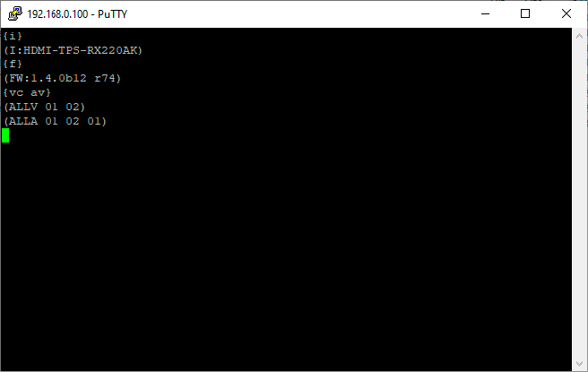
LW2 protocol command communication in a terminal window
6.3. General LW2 Commands
6.3.1. Querying the Supported Commands
The LW2 commands supported by the device can be queried by this command.
Command and Response #producttype
»{LCMD}
«(LCMD# <command>: <description>)CrLf
«...
«(LCMD END)CrLf
Example
»{lcmd}
«(LCMD# LCMD: List all commands)
«(LCMD# PING: Always response PONG)
«(LCMD# CT: Compile time)
«...
«(LCMD END)
INFO:The response is longer, not all the lines can be seen in the example.
6.3.2. Querying the Product Type
The device responds its name.
Command and Response #producttype
»{i}
«(I:<PRODUCT_TYPE>)CrLf
Example
»{i}
«(I:RAP-B511-US-W)
6.3.3. Querying the Device Label
The respond shows the device label which is a read-only parameter in LW2, but it can be changed by an LW3 command, see the Set the Device Label section.
Command and Response
»{LABEL}
«(LABEL=<device_label>)CrLf
Example
»{label}
«(LABEL=RAP-B511_ENG-6517)
6.3.4. Querying the Control Protocol
The device can be controlled with different control protocols. This command queries the active protocol of the currently used control interface.
Command and Response #protocol
»{P_?}
«(CURRENT·PROTOCOL·=·#<protocol>)CrLf
Example
»{p_?}
«(CURRENT PROTOCOL = #1)
'#1' means the device communicates with LW2 protocol.
6.3.5. Querying the Current Firmware Package Version
Command and Response
»{F}
«(FW:<FW_VER>)CrLf
Example
»{f}
«(FW:1.0.3b2)
<FW_VER> is the firmware package version.
6.3.6. View Firmware for All Controllers
Shows the firmware versions of all installed controllers.
Command and Response #firmwareversion
»{FC}
«(CF·<DESC>)CrLf
«(CF·<DESC>)CrLf
«…
«(CF END)CrLf
Example
»{fc}
«(CF RAP-B511-US-W v1.0.3b2)
«(CF END)
The device has one control panel.
Simple test to see if the connection is established successfully.
Command and Response
»{PING}
«(PONG!)CrLf
Example
»{ping}
«(PONG!)
6.3.8. Querying the Serial Number
The device responds its 8-digit serial number; see the structure in the About the Serial Number section.
Command and Response #serialnumber
»{S}
«(SN:<SERIAL_N>)CrLf
Example
»{s}
«(SN:5A004254)
6.3.9. Compile Time
Returns the date, when the CPU firmware was compiled.
Command and Response
»{CT}
«(Complied: <DATE&TIME>)CrLf
Example
»{ct}
«(Compiled: May 8 2020 12:16:47)
6.3.10. Querying the Health Status
Internal voltages and measured temperature values are shown.
Command and Response #status
»{ST}
«(ST·<DESC>)CrLf
Example
»{st}
«(ST CPU 3.32V 4.98V 1.81V 3.36V 44.37C 44.38C)
6.3.11. View Installed Board
Shows the hardware name and revision of the installed cards.
Command and Response
»{IS}
«(SL#·0·<MB_DESC>)CrLf
«(SL·END)CrLf
Example
»{is}
«(SL# 0 RAP-B511)
«(SL END)
The device reports its motherboard (slot 0).
6.3.12. Restarting the Device
The device can be restarted without unplugging power.
Command and Response #reboot #restart
»{RST}
«
Example
»{rst}
«
The device reboots; no response is sent in this case.
«
6.3.13. Restoring the Factory Default Settings
Settings can be reset to factory default values as follows:
Command and Response #factory
»{FACTORY=ALL}
«(FACTORY ALL…)CrLf
Example
»{factory=all}
«(FACTORY ALL…).
All settings and parameters are reset to factory default, see the table in the Factory Default Settings section.
6.4. Network Configuration
6.4.1. Querying the Current IP Status
The IP address settings can be queried as follows. #dhcp #ipaddress #network
Command and Response
»{IP_STAT=?}
«(IP_STAT=<type>;<ip_address>;<subnet_mask>;<gateway_addr>)CrLf
Parameters
|
Parameter |
Parameter description |
Value |
Value description |
|
<type> |
Assignment of the IP address |
0 |
static |
|
1 |
dynamic (DHCP) |
||
|
<ip_addr> |
IP address |
(four decimal octets separated by dots) |
|
|
<subnet_mask> |
Subnet mask |
(four decimal octets separated by dots) |
|
|
<gateway_addr> |
Gateway address |
(four decimal octets separated by dots) |
|
Example
»{ip_stat=?}
«(IP_STAT=0;192.168.0.100;255.255.255.0;192.168.0.1)
The device has a static (fix) IP address: 192.168.0.100; the subnet mask is 255.255.255.0, the gateway address is 192.168.0.1.
IP address can be set as follows.
Command and Response
»{IP_ADDRESS=<type>;<ip_address>}
«(IP_ADDRESS=<type>;<ip_address>)CrLf
Parameters
See the previous section.
Example
»{ip_address=0;192.168.0.110}
«(IP_ADDRESS=0;192.168.0.110)
INFO:The IP address can be queried by typing the {ip_address=?} command. The response contains the fix IP address that is stored in the device even if DHCP is enabled; in this case, this IP address is not valid.
6.4.3. Setting the Subnet Mask
Subnet mask can be set as follows.
Command and Response
»{IP_NETMASK=<subnet_mask>}
«(IP_NETMASK=<subnet_mask>)CrLf
Parameters
See the Querying the Current IP Status section.
Example
»{ip_netmask=255.255.255.0}
«(IP_NETMASK=255.255.255.0)
INFO:The subnet mask can be queried by typing the {ip_address=?} command. The response contains the fix IP subnet mask that is stored in the device even if DHCP is enabled; in this case, this IP subnet mask is not valid.
6.4.4. Setting the Gateway Address
Gateway address can be set as follows.
Command and Response
»{IP_GATEWAY=<gateway_addr>}
«(IP_GATEWAY=<gateway_addr>)CrLf
Parameters
See the Querying the Current IP Status section.
Example
»{ip_gateway=192.168.0.50}
«(IP_GATEWAY=192.168.0.50)
INFO:The gateway address can be queried by typing the {ip_gateway=?} command. The response contains the static IP gateway address that is stored in the device even if DHCP is enabled. In that case, the latest valid gateway address (for static IP) is stored.
6.4.5. Applying the Network Settings
Apply the network settings and restart the network interface.
Command and Response
»{ip_apply}
«(IP_APPLY)CrLf
Example
»{ip_apply}
«(IP_APPLY)
6.4.6. Enable/disable the Ethernet Port
Command and Response
»{ETH_ENABLE=<switch>}
«(ETH_ENABLE=<switch>)CrLf
Parameters
If the <switch> parameter is 0, the port is disabled. If its value is 1, the port is enabled.
Example
»{ETH_ENABLE=1}
«(ETH_ENABLE=1)
6.5. GPIO Port Configuration
6.5.1. Setting the Level and Direction for Each Pins
GPIO pins can be configured as follows. See more details about GPIO connector in the GPIO - General Purpose Input/Output Ports section.
Command and Response #gpio
»{GPIO<pin_nr>=<dir>;<level>}
«(GPIO<pin_nr>=<dir>;<level>)CrLf
Parameters
|
Parameter |
Parameter description |
Value |
Value description |
|
<pin_nr> |
GPIO pin number |
0-3 |
static |
|
<dir> |
The direction of the communication |
I |
Input |
|
O |
Output |
||
|
<level> |
The level of the pin |
L |
Low |
|
H |
High |
||
|
T |
Toggle between low and high |
Example
»{gpio1=O;H}
«(GPIO1=O;H)
GPIO pin 1 is set to output with high level.
INFO:The current GPIO pin configuration can be queried by typing the {GPIO<pin_nr>=?} command.
6.6. LW2 Commands – Quick Summary
The device can be controlled through Lightware 3 (LW3) protocol commands to ensure the compatibility with other Lightware products. The supported LW3 commands are described in this chapter.
7.1. Overview
The Lightware Protocol #3 (LW3) is implemented in almost all new Lightware devices (matrix switchers, signal extenders and distribution amplifiers) since 2012. The protocol is ASCII-based and all commands are terminated with a carriage return (Cr, ‘\r’) and line feed (Lf, ‘\n’) pair. It is organized as a tree structure that provides outstanding flexibility and user-friendly handling with ‘nodes’, ‘properties’ and ‘methods’. The Advanced View of the Lightware Device Controller software is the perfect tool for browsing and learning how the LW3 protocol can be used in practice.
7.2. Instructions for the Terminal Application Usage

Terminal Application
The LW3 protocol commands can be applied to the receiver using a terminal application. You need to install one of them to your control device, for example Putty or CLI. #terminal
Establishing Connection
Follow the steps for establishing connection to the receiver:
Step 1.Connect the receiver to a LAN over Ethernet.
Step 2.Open the terminal application (e.g. Putty).
Step 3.Add the IP address of the device (default: 192.168.0.100) and the port number (6107).
Step 4.Select the Raw connection type, and open the connection.
Once the terminal window is opened, you can enter the LW3 protocol commands which are listed in the following sections.

LW3 protocol command communication in a terminal window
7.3. Protocol Rules
7.3.1. LW3 Tree Structure and Command Structure (examples)

7.3.2. General Rules
▪All names and parameters are case-sensitive.
▪The nodes are separated by a slash (‘/’) character.
▪The node name can contain the elements of the English alphabet and numbers.
▪The command lines have to be closed by Carriage return and Line Feed (CrLf).
▪Use the TCP port no. 6107 when using LW3 protocol over Ethernet.
▪The length of a line (command/response, command type / prefix, path, method/property and parameters together) can be max. 800 byte.
▪When a command is issued by the device, the received response cannot be processed by the CPU.
▪The node paths describe the exact location of the node, listing each parent node up to the root.
7.3.3. Command Types
GET command
The GET command can be used to get the child nodes, properties and methods of a specific node. It can also be used to get the value of a property. Use the dot character (.) when addressing a property:
»GET /.SerialNumber
«pr /.SerialNumber=87654321
GETALL command
The GETALL command can be used to get all child nodes, properties and methods of a node with one command.
»GETALL /MEDIA/UART
«ns /MEDIA/UART/P1
«ns /MEDIA/UART/RECOGNIZER
«pr /MEDIA/UART.PortCount=1
«pr /MEDIA/UART.PortUi=P1:01209
«pr /MEDIA/UART.P1=Local RS-232
SET command
The SET command can be used to modify the value of a property. Use the dot character (.) when addressing the property:
»SET /MANAGEMENT/UI/BUTTONS/BUTTON1.Enabled=false
«pw /MANAGEMENT/UI/BUTTONS/BUTTON1.Enabled=false
CALL command
A method can be invoked by the CALL command. Use the colon character (:) when addressing the method:
»CALL /MANAGEMENT/UI/BUTTONS/BUTTON1:factoryDefaults()
«mO /MANAGEMENT/UI/BUTTONS/BUTTON1:factoryDefaults
MAN command
The manual is a human readable text that describes the syntax and provides a hint for how to use the primitives. For every node, property and method in the tree there is a manual, type the MAN command to get the manual:
»MAN /MANAGEMENT/UI/LEDS/LED1.TrueFunction
«pm /MANAGEMENT/UI/LEDS/LED1.TrueFunction [0-5] 0: off, 1: low, 2: high, 3: blink, 4: slow blink, 5: sine pulse
7.3.4. Prefix Summary
DEFINITION:The prefix is a 2-character long code that describes the type of the response.
The following prefixes are defined in the LW3 protocol:
|
Prefix |
Description |
|
n- |
a node |
|
nE |
an error for a node |
|
nm |
a manual for a node |
|
pr |
a read-only property |
|
pw |
read-write property |
|
pE |
an error for the property |
|
pm |
a manual for the property |
|
m- |
a method |
|
mO |
a response after a success method execution |
|
mF |
a response after a failed method execution |
|
mE |
an error for a method |
|
mm |
a manual for a method |
7.3.5. Error Messages
There are several error messages defined in the LW3 protocol, all of them have a unique error number.
»CALL /MEDIA/VIDEO/XP:switch(IA:O1)
«nE /MEDIA/VIDEO/XP %E002:Not exists
DEFINITION:An escape sequence is a sequence of characters that does not represent itself when used inside a character or string literal, but is translated into another character or a sequence of characters.
Property values and method parameters can contain characters which are used as control characters in the protocol. They must be escaped. The escape character is the backslash (‘\’) and escaping means injecting a backslash before the character that should be escaped (like in C language).
Control characters are the following: \ { } # % ( ) \r \n \t
The original message: CALL /MEDIA/UART/P1:sendMessage(Set(01))
The escaped message: CALL /MEDIA/UART/P1:sendMessage(Set\(01\))
7.3.7. Signature
DEFINITION:The signature is a four-digit-long hexadecimal value that can be optionally placed before every command to keep a command and the corresponding responses together as a group.
Each line is terminated with a carriage return (Cr, ‘\r’) and line feed (Lf, ‘\n’) characters. In several cases the number of the lines in the response cannot be determined in advance, e.g. the client intends to receive for the whole response and also wants to be sure, that the received lines belong together and to the same command. In these cases, a special feature the ‘signature’ can be used. The response to that particular command will also be preceded by the signature, and the corresponding lines will be between brackets:
»GET /MEDIA/IR.*
«pr /MEDIA/IR.PortCount=1
«pr /MEDIA/IR.PortUi=S1:13313
«pr /MEDIA/IR.S1=IR in
INFO:The lines of the signature are also Cr and Lf terminated.
DEFINITION:Subscription to a node means that the user will get a notification if a property of the node changes.
A user can subscribe to any node. These notifications are asynchronous messages and are useful to keep the client application up to date, without having to periodically poll the node to detect a changed property. When the user does not want to be informed about the changes anymore, he can simply unsubscribe from the node.
ATTENTION!The subscriptions are handled separately for connections. Hence, if the connection is terminated all registered subscriptions are deleted. After reopening a connection all subscribe commands have to be sent in order to get the notifications of the changes on that connection.
Subscribe to a Node
»OPEN /MEDIA/IR
«o- /MEDIA/IR
Get the Active Subscriptions
»OPEN
«os /MEDIA/IR/S1
«o- /MANAGEMENT/UI/BUTTONS/BUTTON1
«o- /MANAGEMENT/UI/LEDS/LED1
«o- /MANAGEMENT/UI/VOLUMECONTROL
«o- /MANAGEMENT/LABEL
Subscribe to Multiple Nodes
»OPEN /MEDIA/ETHERNET/*
«o- /MEDIA/ETHERNET/*
Unsubscribe from a Node
»CLOSE /MEDIA/ETHERNET
«c- /MEDIA/ETHERNET
Unsubscribe from Multiple Nodes
»CLOSE /MEDIA/ETHERNET/*
«c- /MEDIA/ETHERNET/*
7.3.9. Notifications about the Changes of the Properties
When the value of a property is changed and the user is subscribed to the node, which the property belongs to, an asynchronous notification is generated. This is notification is called as the ‘change message’. The format of such a message is very similar to the response for the GET command:
«CHG /EDID.EdidStatus=F48:E1
A Short Example of How to Use the Subscription
There are two independent users controlling the device through two independent connections (Connection #1 and Connection #2). The events in the rows occur after each other.
|
»OPEN /MEDIA/AUDIO/O3 «o- /MEDIA/AUDIO/O3 »GET /MEDIA/AUDIO/O3.VolumePercent «pw /MEDIA/AUDIO/O3.VolumePercent=100.00 |
connection #1 |
|
»GET /MEDIA/AUDIO/O3.VolumePercent «pw /MEDIA/AUDIO/O3.VolumePercent=100.00 »SET /MEDIA/AUDIO/O3.VolumePercent=50.00 «pw /MEDIA/AUDIO/O3.VolumePercent=50.00 |
connection #2 |
|
«CHG /MEDIA/AUDIO/O3.VolumePercent=50.00 |
connection #1 |
The first user (Connection #1) set a subscription to a node. Later the other user (Connection #2) made a change, and thanks for the subscription, the first user got a notification about the change.
7.3.10. Legend for the Control Commands
|
Format |
Description |
|
<in> |
Input port number |
|
<out> |
Output port number |
|
<port> |
Input or output port number |
|
<loc> |
Location number |
|
<parameter> |
Specific property, which is defined and described in the command |
|
<expression> |
Batched parameters: the underline means that more expressions or parameters can be placed by using a semicolon, e.g. I2;I4;I5 or F27:E1;F47:E2 |
|
» |
Sent command |
|
« |
Received response |
|
· |
Space character |
7.4. System Commands
The name of the product is a read-only parameter and cannot be modified.
Command and Response
»GET·/.ProductName
«pr·/.ProductName=<product_name>
Example
»GET /.ProductName
«pr /.ProductName=RAP-B511-EU-K
This property can be changed to a custom text. The default format of the device label is the following:
LW_<product_name>_<serial_no>
ATTENTION!The device label can be changed to a custom text in the Status tab of the LDC software. This writable parameter is not the same as the ProductName parameter.
Command and Response
»SET·/MANAGEMENT/LABEL.DeviceLabel=<custom_name>
«pw·/MANAGEMENT/LABEL.DeviceLabel=<custom_name>
The Device Label can be 31 character length and ASCII characters are allowed. Longer names are truncated.
Example
»SET /MANAGEMENT/LABEL.DeviceLabel=RAP-B511
«pw /MANAGEMENT/LABEL.DeviceLabel=RAP-B511
7.4.3. Query the Serial Number
Command and Response
»GET·/.SerialNumber
«pr·/.SerialNumber=<serial_nr>
Example
»GET /.SerialNumber
«pr /.SerialNumber=00009865
7.4.4. Query the Firmware Version
Command and Response
»GET·/SYS/MB.FirmwareVersion
«pr·/SYS/MB.FirmwareVersion=<firmware_version>
Example
»GET /SYS/MB.FirmwareVersion
«pr /SYS/MB.FirmwareVersion= v1.0.1b2
7.4.5. Resetting the Device
The device can be restarted – the current connections (LAN, RS-232 or USB) will be terminated.
Command and Response
»CALL·/SYS:reset()
«mO·/SYS:reset=
Example
»CALL /SYS:reset()
«mO /SYS:reset=
7.4.6. Restore the Factory Default Settings
Command and Response
»CALL·/SYS:factoryDefaults()
«mO·/SYS:factoryDefaults=
Example
»CALL /SYS:factoryDefaults()
«mO /SYS:factoryDefaults=
The device is restarted, current connections are terminated, and the default settings are restored. See the complete list in the Factory Default Settings section.
7.4.7. Enable PoE
Command and Response
»SET·/SYS/MB/POE.PoeEnabled=<PoE_status>
«pw·/SYS/MB/POE.PoeEnabled=<PoE_status>
Parameters
|
Identifier |
Parameter description |
|
<PoE_status> |
true: PoE sending is enabled on the P2 Ethernet port. false: PoE sending is enabled on the P2 Ethernet port. |
Example
»SET /SYS/MB/POE.PoeEnabled=true
«pw /SYS/MB/POE.PoeEnabled=true
INFO:The RAP-B511 sends PoE when the connected device is also PoE-compatible.
7.4.8. Running a Macro
DIFFERENCE:This command is available from FW package v1.1.0b3.
DEFINITION:Macro is a batch of pre-defined commands stored in the device. #macro
You can create your custom macros in a file, upload to the device and run at any time. The uploading can be done over LDC, see the Uploading New Macros into a New Preset section. The following LW3 command is suitable only for running a macro.
Command and Response
»CALL·/CTRL/MACROS:run(<macro_name>)
«mO·/CTRL/MACROS:run
Example
»CALL /CTRL/MACROS:run(Macro1)
«mO /CTRL/MACROS:run
7.5. Cleartext Login Protection
DIFFERENCE:This feature and below commands are available from FW package v1.1.0b3.
This cleartext login tool allows setting a password for login, thus, any change in the device can be performed only after a successful login – coming from any control interface (RS-232, Ethernet, etc…). The login is valid until a TCP socket break in case of Ethernet connection. #login
ATTENTION!If the login is enabled, the miniweb is not available.
INFO:The login password is erased and the login is disabled when restoring the factory default values.
The following can be queried without login:
▪ProductName
▪PartNumber
▪SerialNumber
▪FirmwareVersion
▪PackageVersion
▪MacAddress
7.5.1. Setting the Login Password
Command and Response
»CALL·/LOGIN:setPassword(<password>)
«mO·/LOGIN:setPassword
Example
»CALL /LOGIN:setPassword(pr0t3ctED)
«mO /LOGIN:setPassword
Command and Response
»CALL·/LOGIN:login(<password>)
«mO·/LOGIN:login
Example
»CALL /LOGIN:login(pr0t3ctED)
«mO /LOGIN:login
After a successful login, the LoggedIn property becomes true and the LW3 tree is available.
7.5.3. Logout from the Device
Command and Response
»CALL·/LOGIN:logout(<password>)
«mO·/LOGIN:logout
Example
»CALL /LOGIN:logout(pr0t3ctED)
«mO /LOGIN:logout
After a successful logout, the LoggedIn property becomes false and the LW3 tree is protected.
7.5.4. Enable the Cleartext Login Function
ATTENTION!This property can be changed only, if the LoggedIn property is true.
Command and Response
»SET·/LOGIN:LoginEnable=<login_state>
«pw·/LOGIN.LoginEnable=<login_state>
Parameters
If the <login_state> parameter is true (or 1), the Cleartext login function is enabled, if the parameter is false (or 0), the function is disabled. Please note that the function can be enabled without setting a password by the setPassword method.
Example
»SET /LOGIN.LoginEnable=true
«pw /LOGIN.LoginEnable=true
7.6.1. Query the Timezone
Command and Response
»SET·/SYS/MB/TIMEZONE.Timezone=<timezone>
«pw·/SYS/MB/TIMEZONE.Timezone =<timezone>
Parameters
|
Identifier |
Parameter description |
|
<timezone> |
Time zone setting in POSIX TZ format. |
Example
»SET /SYS/MB/TIMEZONE.Timezone=CET-1CEST,M3.5.0/2,M10.5.0/3
«pw /SYS/MB/TIMEZONE.Timezone=CET-1CEST,M3.5.0/2,M10.5.0/3
TIPS AND TRICKS:Timezone and daylight saving settings can be done easily and quickly with Lightware Device Controller software in the Time Settings section.
TIPS AND TRICKS:Enable Network Time Protocol (NTP)
Enabling Network Time Protocol means, that the RAP-B511 is permitted to get time information from an NTP server. The device time synchronized repeatedly and automatically.
Command and Response
»SET·/SYS/MB/NTP.Enable=<enable_ntp>
«pw·/SYS/MB/NTP.Enable=<enable_ntp>
Parameters
|
Identifier |
Parameter description |
|
<enable_ntp> |
true: NTP enabled false: NTP disabled |
Example
»SET /SYS/MB/NTP.Enable=true
«pw /SYS/MB/NTP.Enable=true
7.6.2. Enable Getting NTP from DHCP server
When the DHCP server assigns an IP address to the device, there is an option to request an NTP time information. When the RAP-B511 connected to the internet, the NTP time is updated repeatedly.
Command and Response
»SET·/SYS/MB/NTP.NtpServerFromDhcp=<enable_ntp_dhcp>
«pw·/SYS/MB/NTP.NtpServerFromDhcp=<enable_ntp_dhcp>
Parameters
|
Identifier |
Parameter description |
|
<enable_ntp_dhcp> |
true: Enable getting NTP from the DHCP server. false: Disable getting NTP from the DHCP server. |
Example
»SET /SYS/MB/NTP.NtpServerFromDhcp=true
«pw /SYS/MB/NTP.NtpServerFromDhcp=true
7.6.3. Query the Active NTP Server
Command and Response
»GET·/SYS/MB/NTP.ActiveNtpServer
«pr·/SYS/MB/NTP.ActiveNtpServer=<server_address>
Parameters
|
Identifier |
Parameter description |
|
<server_address> |
NTP server address (IP address or URL). |
Example
»GET /SYS/MB/NTP.ActiveNtpServer
«pr /SYS/MB/NTP.ActiveNtpServer=pool.ntp.org
7.6.4. Set NTP server
Command and Response
»SET·/SYS/MB/NTP.NtpServer=<server_address>
«pw·/SYS/MB/NTP.NtpServer=<server_address>
Parameters
|
Identifier |
Parameter description |
|
<server_address> |
NTP server address (IP address or URL). |
Example
»SET /SYS/MB/NTP.NtpServer=pool.ntp.org
«pw /SYS/MB/NTP.NtpServer=pool.ntp.org
7.6.5. Synchronize with the NTP server
Command and Response
»CALL·/SYS/MB/NTP:updateTime()
«mO·/SYS/MB/NTP:updateTime
Example
»CALL /SYS/MB/NTP:updateTime()
«mO /SYS/MB/NTP:updateTime
7.6.6. Query the Last Synchronization
Command and Response
»GET·/SYS/MB/RTC.LastUpdate
«pr·/SYS/MB/RTC.LastUpdate=<last_sync>
Parameters
|
Identifier |
Parameter description |
|
<last_sync> |
Displays the last synchronization time. |
Example
»GET /SYS/MB/RTC.LastUpdate
«pr /SYS/MB/RTC.LastUpdate=2019-04-30T16:36:41
7.6.7. Query the Universal Time Coordinated Time (UTC)
Command and Response
»GET·/SYS/MB/RTC.UtcTime
«pr·/SYS/MB/RTC.UtcTime=<utcTime>
Parameters
|
Identifier |
Parameter description |
|
<utcTime> |
Displays the date and the UTC time. |
Example
»GET /SYS/MB/RTC.UtcTime
«pr /SYS/MB/RTC.UtcTime=2019-05-16T10:41:38
7.6.8. Query the Local Time (RTC)
Command and Response
»GET·/SYS/MB/RTC.LocalTime
«pr·/SYS/MB/RTC.LocalTime=<localtime>
Parameters
|
Identifier |
Parameter description |
|
<localtime> |
Displays the date and the local time. |
Example
»GET /SYS/MB/RTC.LocalTime
«pr /SYS/MB/RTC.LocalTime=2019-02-14T17:16:14
7.6.9. Query the Local Time (RTC) Elements
TIPS AND TRICKS:When repetitive scheduled actions are required, these properties should be set as a condition in the Event Manager.
Command and Response
»GET·/SYS/MB/RTC.<RTC_element>
«pr·/SYS/MB/RTC.LocalTime=<RTC_element>
Parameters
|
Identifier |
Parameter description |
Parameter example |
|
<RTC_element> |
Years |
2019 (four digit number between 2000 and 2099) |
|
Months |
12 (max. two digit number between 1 and 12) |
|
|
Days |
7 (max. two digit number between 1 and 31) |
|
|
Hours |
9 (max. two digit number between 0 and 24) |
|
|
Minutes |
54 (max. two digit number between 0 and 59) |
|
|
Seconds |
11 (max. two digit number between 0 and 59) |
|
|
DaylightSaving |
true or false |
|
|
Weekday |
1: Monday; 2: Tuesday; 3: Wednesday; 4: Thursday 5: Friday; 6: Saturday; 7: Sunday It shows the which day is on the week. |
|
|
Yearday |
193 (max. two digit number between 1 and 365) It shows the which day is in the year. |
|
|
Scheduler time |
5-18-19 (Weekday-Hours-Minutes) |
Example
»GET /SYS/MB/RTC.Years
«pr /SYS/MB/RTC.Years=2019
DIFFERENCE:This section relates to RAP-B511 series models only.
General parameters
|
Identifier |
Parameter description |
Parameter values |
|
<btn_ID> |
Button identifier |
BUTTON1-BUTTON11 |
7.7.1. Lock the Front Panel Functionality
Command and Response
»SET·/MANAGEMENT/UI.ControlLock=<lock_status>
«pw·/MANAGEMENT/UI.ControlLock=<lock_status>
Parameters
|
Identifier |
Parameter description |
Parameter values |
|
<lock_status> |
0: None - All functions of the front panel buttons and the rotary are enabled. |
|
|
1: Locked - Locking and unlocking of the front panel buttons and the rotary are possible with Lightware Device Controller software or via protocol command. |
Example
»SET /MANAGEMENT/UI.ControlLock=1
«pw /MANAGEMENT/UI.ControlLock=1
7.7.2. Lock the Buttons Separately
Command and Response
»SET·/MANAGEMENT/UI/BUTTONS/<btn_ID>.Enabled=<btn_lock_status>
«pw·/MANAGEMENT/UI/BUTTONS/<btn_ID>.Enabled= <btn_lock_status>
Parameters
|
Identifier |
Parameter description |
Parameter values |
|
<btn_lock_status> |
true: On buttonpress event, the funcitonality of the button is enabled. false: On buttonpress event, the funcitonality of the button is disabled. |
Example
»SET /MANAGEMENT/UI/BUTTONS/BUTTON1.Enabled=false
«pw /MANAGEMENT/UI/BUTTONS/BUTTON1.Enabled=false
7.7.3. Set the Button Operation Mode
Command and Response
»SET·/MANAGEMENT/UI/BUTTONS/<btn_ID>.Mode=<btn_mode>
«pw·/MANAGEMENT/UI/BUTTONS/<btn_ID>.Mode=<btn_mode>
Parameters
|
Identifier |
Parameter description |
Parameter values |
|
<btn_mode> |
Shows the button type.It can be momentary or toggle or radio. |
0: Momentary: Simple button function, when the button is pressed, the action will execute. ▪When the button is pressed, the <btn_ID>.State-=true ▪When the button is released, the <btn_ID>.State=false 1: Toggle: This button type toggles between two states ▪When the button is pressed, the <btn_ID>.State changes. ▪When the button is released, the <btn_ID>.State does not change. 2-6: Radio: It defines the assigned radio group of the button. One button can belong to one group at the same time. When the button is pressed, the <btn_ID>.State changes true and <btn_ID>.State of the other members in the same group changes false. 2: Member of group 1; 3: Member of group 2; 6: Member of group 5. |
Example
»SET /MANAGEMENT/UI/BUTTONS/BUTTON1.Mode=1
«pw /MANAGEMENT/UI/BUTTONS/BUTTON1.Mode=1
7.7.4. Set the Button Interaction State
This property gives immediate feedback about the button status, which changes depending on the button mode. When the button function is configured with Lightware Device Controller Software, this parameter is set as a Condition in the Event Manager.
Command and Response
»SET·/MANAGEMENT/UI/BUTTONS/<btn_ID>.State=<btn_state>
«pw·/MANAGEMENT/UI/BUTTONS/<btn_ID>.State=<btn_state>
Parameters
|
Identifier |
Parameter description |
Parameter values |
|
<btn_state> |
Button state |
true or false: It gives a feedback about the current state of the button, which changes depending on the Set the Button Operation Mode. |
Example
»SET /MANAGEMENT/UI/BUTTONS/BUTTON1.State=true
»pw /MANAGEMENT/UI/BUTTONS/BUTTON1.State=true
7.7.5. Set the Button Name
Command and Response
»SET·/MANAGEMENT/UI/BUTTONS/<btn_ID>. Name=<btn_name>
«pw·/MANAGEMENT/UI/BUTTONS/<btn_ID>. Name=<btn_name>
Parameters
|
Identifier |
Parameter description |
Parameter values |
|
<btn_name> |
Button name |
The button name can be 33 character-long, ASCII characters are allowed. Longer names are not accepted. |
Example
»SET /MANAGEMENT/UI/BUTTONS/BUTTON1.Name=Projector on
»pw /MANAGEMENT/UI/BUTTONS/BUTTON1.Name=Projector on
7.7.6. Set the Icon for the Button
Command and Response
»SET·/MANAGEMENT/UI/BUTTONS/<btn_ID>.IconId=<icon_ID>
«pw·/MANAGEMENT/UI/BUTTONS/<btn_ID>. IconId=<icon_ID>
Parameters
|
Identifier |
Parameter description |
Parameter values |
|
<icon_ID> |
It defines the displayed icon of the button in the Miniweb or the LDC layout. |
i1-i140: Sets the pictogram on the button. |
|
Button Icon and IDs |
|||||||||||||

|

|

|

|

|

|

|

|

|

|

|

|

|
|
|
i1 |
i2 |
i3 |
i4 |
i5 |
i6 |
i7 |
i8 |
i9 |
i10 |
i11 |
i12 |
i13 |
i14 |
|
|

|
|
|
|
|

|
|

|
|
|

|
|
|
|
i15 |
i16 |
i17 |
i18 |
i19 |
i20 |
i21 |
i22 |
i23 |
i24 |
i25 |
i26 |
i27 |
i28 |
|
|

|

|
|
|

|

|

|
|

|
|

|
|

|
|
i29 |
i30 |
i31 |
i32 |
i33 |
i34 |
i35 |
i36 |
i37 |
i38 |
i39 |
i40 |
i41 |
i42 |

|

|

|

|

|

|

|
|

|
|
|

|
|
|
|
i43 |
i44 |
i45 |
i46 |
i47 |
i48 |
i49 |
i50 |
i51 |
i52 |
i53 |
i54 |
i55 |
i56 |
|
|

|
|

|
|

|
|

|
|

|

|
|

|
|
|
i57 |
i58 |
i59 |
i60 |
i61 |
i62 |
i63 |
i64 |
i65 |
i66 |
i67 |
i68 |
i69 |
i70 |
|
|

|

|

|

|

|

|

|
|

|
|
|
|
|
|
i71 |
i72 |
i73 |
i74 |
i75 |
i76 |
i77 |
i78 |
i79 |
i80 |
i81 |
i82 |
i83 |
i84 |
|
|
|

|

|
|

|
|
|

|
|
|
|

|

|
|
i85 |
i86 |
i87 |
i88 |
i89 |
i90 |
i91 |
i92 |
i93 |
i94 |
i95 |
i96 |
i97 |
i98 |

|
|
|

|

|

|

|

|

|

|

|

|

|
|
|
i99 |
i100 |
i101 |
i102 |
i103 |
i104 |
i105 |
i106 |
i107 |
i108 |
i109 |
i110 |
i111 |
i112 |
|
|

|
|

|
|

|
|
|
|
|

|

|
|
|
|
i113 |
i114 |
i115 |
i116 |
i117 |
i118 |
i119 |
i120 |
i121 |
i122 |
i123 |
i124 |
i125 |
i126 |

|
|

|

|

|
|
|

|

|

|

|
|
|

|
|
i127 |
i128 |
i129 |
i130 |
i131 |
i132 |
i133 |
i134 |
i135 |
i136 |
i137 |
i138 |
i139 |
i140 |
Example
»SET /MANAGEMENT/UI/BUTTONS/BUTTON2.IconId=i139
»pw /MANAGEMENT/UI/BUTTONS/BUTTON2.IconId=i139
7.7.7. Set the Label for the Button

Command and Response
»SET·/MANAGEMENT/UI/BUTTONS/<btn_ID>. IconId=<row1>;<row2>;<row3>
«pw·/MANAGEMENT/UI/BUTTONS/<btn_ID>. IconId=<row1>;<row2>;<row3>
Parameters
|
Identifier |
Parameter description |
Parameter values |
|
<row1>;<row2>;<row3> |
It defines the displayed text of the button in the Miniweb or the LDC layout. |
Maximum three rows can be displayed for one button separated with semicolon. 30 ASCII characters are allowed for all rows. |
Example
»SET /MANAGEMENT/UI/BUTTONS/BUTTON1.IconId=DP;laptop;on
»pw /MANAGEMENT/UI/BUTTONS/BUTTON1.IconId=DP;laptop;on
7.7.8. Clear the Button Style
The buttons style deleted when IconId has no parameter.
Command and Response
»SET·/MANAGEMENT/UI/BUTTONS/<btn_ID>. IconId=
«pw·/MANAGEMENT/UI/BUTTONS/<btn_ID>. IconId=
Example
»SET /MANAGEMENT/UI/BUTTONS/BUTTON1.IconId=
»pw /MANAGEMENT/UI/BUTTONS/BUTTON1.IconId=
7.7.9. Button Status Indicators
Query the Latch
Command and Response
»GET·/MANAGEMENT/UI/BUTTONS/<btn_ID>/BUTTON.Latch
«pr·/MANAGEMENT/UI/BUTTONS/<btn_ID>/BUTTON.Latch=<btn_latch_status>
Parameters
|
Identifier |
Parameter description |
Parameter values |
|
<btn_latch_status> |
When the button is pressed, the latch property toggles between true and false values every time. This property operates independently of the Set the Button Operation Mode. |
True or False. |
Example
»GET /MANAGEMENT/UI/BUTTONS/BUTTON1/BUTTON.Latch
«pw /MANAGEMENT/UI/BUTTONS/BUTTON1/BUTTON.Latch=false
Query the Actual Status
Command and Response
»GET·/MANAGEMENT/UI/BUTTONS/<btn_ID>/BUTTON.ActualStatus
«pr·/MANAGEMENT/UI/BUTTONS/<btn_ID>/BUTTON.ActualStatus=<btn_status>
Parameters
|
Identifier |
Parameter description |
Parameter values |
|
<btn_status> |
Shows if the button is pressed or not at the moment. |
up: The button is not pressed at the moment. down: The button is pressed at the moment. |
Example
»GET /MANAGEMENT/UI/BUTTONS/BUTTON1/BUTTON.ActualStatus
«pr /MANAGEMENT/UI/BUTTONS/BUTTON1/BUTTON.ActualStatus=up
Command and Response
»GET·/MANAGEMENT/UI/BUTTONS/<btn_ID>/BUTTON.Clicked
«pr·/MANAGEMENT/UI/BUTTONS/<btn_ID>/BUTTON.Clicked=<clicked_nr>
Parameters
The <clicked_nr> parameter gives feedback about the number of the quick button presses (max. 1 sec between the presses). After the clicking, the value restores to default (0) immediately. It can be set as a condition in the Event Manager when the trigger should be e.g. a double click.
Example
»GET /MANAGEMENT/UI/BUTTONS/BUTTON1/BUTTON.Clicked
«pr /MANAGEMENT/UI/BUTTONS/BUTTON1/BUTTON.Clicked=0
Query the Longpress Status
Command and Response
»GET·/MANAGEMENT/UI/BUTTONS/<btn_ID>/BUTTON.LongPress
«pr·/MANAGEMENT/UI/BUTTONS/<btn_ID>/BUTTON.LongPress=<longpress_status>
Parameters
|
Identifier |
Parameter description |
Parameter values |
|
<longpress_status> |
True, when the button has been pressing more than 1 sec. |
true: The button has been pressed more than 1sec. false: The button has been pressed less than 1 sec. |
Example
»GET /MANAGEMENT/UI/BUTTONS/BUTTON1/BUTTON.LongPress
«pr /MANAGEMENT/UI/BUTTONS/BUTTON1/BUTTON.LongPress=false
DIFFERENCE:This section relates to RAP-B511 series models only.
General parameters
|
Identifier |
Parameter description |
Parameter values |
|
<LED_ID> |
LED identifier (LED1 is behind the BUTTON1) |
LED1-11 |
7.8.1. Enable the Button LED
ATTENTION!If the Button LED is not enabled, the following LED-related settings will not be displayed.
Command and Response
»SET·/MANAGEMENT/UI/LEDS/<LED_ID>.Enabled=<LED_enable>
«pw·/MANAGEMENT/UI/LEDS/<LED_ID>.Enabled=<LED_enable>
Parameters
|
Identifier |
Parameter values |
|
<LED_enable> |
true: The button LED is allowed to light. false: The button LED is not allowed to light. |
Example
»SET /MANAGEMENT/UI/LEDS/LED11.Enabled=true
«pw /MANAGEMENT/UI/LEDS/LED11.Enabled=true
7.8.2. Set the Default Intensity of the Low Brightness
Command and Response
»SET·/MANAGEMENT/UI/LEDS.LowBright=<light_intensity>
«pw·/MANAGEMENT/UI/LEDS.LowBright=<light_intensity>
Parameters
|
Identifier |
Parameter description |
Parameter values |
|
<light_intensity> |
The default intensity of the background light. |
0-5:0 means no bright, 5 is the maximum brightness. |
Example
»SET /MANAGEMENT/UI/LEDS.LowBright=1
«pw /MANAGEMENT/UI/LEDS.LowBright=1
7.8.3. Set the Default Intensity of the High Brightness
Command and Response
»SET·/MANAGEMENT/UI/LEDS.HighBright=<light_intensity>
«pw·/MANAGEMENT/UI/LEDS.HighBright=<light_intensity>
Parameters
|
Identifier |
Parameter description |
Parameter values |
|
<light_intensity> |
The default intensity of the background light. |
0-5:0 means no bright, 5 is the maximum brightness. |
Example
»SET /MANAGEMENT/UI/LEDS.HighBright=3
«pw /MANAGEMENT/UI/LEDS.HighBright=3
7.8.4. Set Background Light of the Button
Set the TrueFunction
Here the LEDs behaviour can be defined how the when the button is pressed or released. This property takes into consideration the Set the Button Interaction State. If it is true (<btn_ID>.State=true), the LED will light according to this setting.
Command and Response
»SET·/MANAGEMENT/UI/LEDS/<LED_ID>.TrueFunction=<light_mode>
«pw·/MANAGEMENT/UI/LEDS/<LED_ID>.TrueFunction=<light_mode>
Parameters
|
Identifier |
Parameter description |
Parameter values |
|
<light_mode> |
Type of the background light. |
0: Off 1: Low brightness 2: High brightness 3: Blinking 4: Slow blinking 5: Sine pulse |
Example
»SET /MANAGEMENT/UI/LEDS/LED11.TrueFunction=1
«pw /MANAGEMENT/UI/LEDS/LED11.TrueFunction=1
Set the FalseFunction
Here the LEDs behaviour can be defined, when the button is pressed or released. This property takes into consideration the Set the Button Interaction State. If it is false (<btn_ID>.State=false), the LED will light according to this setting.
Command and Response
»SET·/MANAGEMENT/UI/LEDS/<LED_ID>.FalseFunction=<light_mode>
«pw·/MANAGEMENT/UI/LEDS/<LED_ID>.FalseFunction=<light_mode>
Parameters
|
Identifier |
Parameter description |
Parameter values |
|
<light_mode> |
Type of the background light. |
0: Off 1: Low brightness 2: High brightness 3: Blinking 4: Slow blinking 5: Sine pulse |
Example
»SET /MANAGEMENT/UI/LEDS/LED11.FalseFunction=2
«pw /MANAGEMENT/UI/LEDS/LED11.FalseFunction=2
7.8.5. Set the Background Light for a Period of Time
Command and Response
»CALL·/MANAGEMENT/UI/LEDS/<led_ID>:<button_func>(<time>)
«mO·/MANAGEMENT/UI/LEDS/<led_ID>:<button_func>(<time>)
Parameters
|
Identifier |
Parameter description |
Parameter values |
|
<led_ID> |
LED identifier |
LED1-11 |
|
<button_func> |
Type of the background lightning. |
tempFuncOff: No brightness tempFuncLowBright: Low brightness tempFuncHighBright: High brightness tempFuncBlink: Blinking |
|
<time> |
Duration of time in ms while the LED lights. |
1-60000 |
Example
»CALL /MANAGEMENT/UI/LEDS/LED11:tempFuncOff(100)
«mO /MANAGEMENT/UI/LEDS/LED11:tempFuncOff
7.9. Button Group Configuration
DIFFERENCE:This section relates to RAP-B511 series models only.
7.9.1. Set the Buttons into Groups
The button mode defines which button belongs a certain group. For more information about it, see Set the Button Operation Mode section.
7.9.2. Query the Group Members
Command and Response
»GET·/MANAGEMENT/UI/GROUP/<group_ID>.GroupMembers
«pr·/MANAGEMENT/UI/GROUP/<group_ID>.GroupMembers=<member_list>
Parameters
|
Identifier |
Parameter description |
Parameter values |
|
<group_ID> |
Group identifier |
G1-5 |
|
<member_list> |
Shows which buttons belong to the group. The members are listed with their button ID numbers. |
1-11;1-11;...1-11; |
Example
»GET /MANAGEMENT/UI/GROUP/G1.GroupMembers
«pr /MANAGEMENT/UI/GROUP/G1.GroupMembers=1;2;3;
7.9.3. Set the Active Button
Command and Response
»SET·/MANAGEMENT/UI/GROUP/<group_ID>.Active=<btn_nr>
«pw·/MANAGEMENT/UI/GROUP/<group_ID>.Active=<btn_nr>
Parameters
|
Identifier |
Parameter description |
Parameter values |
|
<group_ID> |
Group identifier |
G1-5 |
|
<btn_nr> |
Shows which button is the active member of the group. |
1-11 |
Example
»SET /MANAGEMENT/UI/GROUP/G1.Active=1
«pw /MANAGEMENT/UI/GROUP/G1.Active=1
7.10. Volume Control Configuration
DIFFERENCE:This section relates to RAP-B511 series models only.
7.10.1. Control Lock of the Jog Dial
This property can disable the control function of the jog dial without locking the buttons.
Command and Response
»SET·/MANAGEMENT/UI/VOLUMECONTROL.Enabled=<enabled>
«pw·/MANAGEMENT/UI/VOLUMECONTROL.Enabled=<enabled>
Parameters
|
Identifier |
Parameter description |
Parameter values |
|
<enabled> |
Enables or disables the jog dial. |
true: Jog dial control is enabled. false: Operation of the jog dial is disabled. The mute LED and Rotary LEDs and are turned down. When the rotary is turned, VOLUMECONTROL.Volume will not change, and the rotary is pressed, the VOLUMECONTROL.Mute property will not toggle. |
Example
»SET /MANAGEMENT/UI/VOLUMECONTROL.Enabled=true
«pw /MANAGEMENT/UI/VOLUMECONTROL.Enabled=true
ATTENTION!When the rotary is disabled, the Query the Rotating Direction of the Jog Dial, Query the Actual Status of the Rotary, Query the Longpress Status, Query the Clicked Status will change.
7.10.2. Set the Volume
Rotating the jog dial changes the volume property value (and turns on and off the volume indicator LEDs) between 0 and 16.
Command and Response
»SET·/MANAGEMENT/UI/VOLUMECONTROL.Volume=<volume_value>
«pw·/MANAGEMENT/UI/VOLUMECONTROL.Volume=<volume_value>
Parameters
|
Identifier |
Parameter values |
|
<volume_value> |
0-16: Volume level can be set between 0 and 16. |
Example
»SET /MANAGEMENT/UI/VOLUMECONTROL.Volume=5
«pw /MANAGEMENT/UI/VOLUMECONTROL.Volume=5
7.10.3. Mute the Volume
Clicking on the jog dial changes the mute state (and toggles on and off the mute LED).
Command and Response
»SET·/MANAGEMENT/UI/VOLUMECONTROL.Mute=<mute_state>
«pw·/MANAGEMENT/UI/VOLUMECONTROL.Mute=<mute_state>
Parameters
|
Identifier |
Parameter description |
Parameter values |
|
<mute_state> |
Enables or disables the mute state. |
true: The volume is muted. false: The volume is unmuted. |
Example
»SET /MANAGEMENT/UI/VOLUMECONTROL.Mute=false
«pw /MANAGEMENT/UI/VOLUMECONTROL.Mute=false
7.10.4. Volume Setting in Mute State
This command allows setting the volume while the controlled device is in muted state.
Command and Response
»SET·/MANAGEMENT/UI/VOLUMECONTROL.UnMuteOnVolumeChange=<unmute>
«pw·/MANAGEMENT/UI/VOLUMECONTROL.UnMuteOnVolumeChange=<unmute>
Parameters
If the <unmute> parameter is true, the unmute command is sent, the LED is switched off and the volume setting command is sent. If the <unmute> parameter is false, only the volume setting command is sent.
Example
»SET /MANAGEMENT/UI/VOLUMECONTROL.UnMuteOnVolumeChange=false
«pw /MANAGEMENT/UI/VOLUMECONTROL.UnMuteOnVolumeChange=false
7.10.5. Volume Control (Jog Dial) Status Indicators
These properties gives immediate feedback about the jog dial status. They are for using as a Condition in the Event Manager.
Query the Rotating Direction of the Jog Dial
Command and Response
»GET·/MANAGEMENT/UI/VOLUMECONTROL/ROTARY.RotaryPosition
«pw·/MANAGEMENT/UI/VOLUMECONTROL/ROTARY.RotaryPosition=<direction>
Parameters
If the <direction> parameter is 1, the jog dial is rotating clockwise. If the value is -1, the jog dial is rotating counter clockwise. 0 value means the rotary does not turn (default value).
Example
»GET /MANAGEMENT/UI/VOLUMECONTROL/ROTARY.RotaryPosition
«pr /MANAGEMENT/UI/VOLUMECONTROL/ROTARY.RotaryPosition=-1
Query the Actual Status of the Rotary
Command and Response
»GET·/MANAGEMENT/UI/VOLUMECONTROL/ROTARY.ActualStatus
«pr·/MANAGEMENT/UI/VOLUMECONTROL/ROTARY.ActualStatus=<rotary_status>
Parameters
|
Identifier |
Parameter description |
Parameter values |
|
<rotary_status> |
Shows if the rotary button is pressed or not at the moment. |
up: The rotary button is not pressed at the moment. down: The rotary button is pressed at the moment. |
Example
»GET /MANAGEMENT/UI/VOLUMECONTROL/ROTARY.ActualStatus
«pr /MANAGEMENT/UI/VOLUMECONTROL/ROTARY.ActualStatus=up
Command and Response
»GET·/MANAGEMENT/UI/VOLUMECONTROL/ROTARY.LongPress
«pr·/MANAGEMENT/UI/VOLUMECONTROL/ROTARY.LongPress=<longpress_status>
Parameters
|
Identifier |
Parameter description |
Parameter values |
|
<longpress_status> |
True, when the rotary button has been pressing more than 1 sec. |
true: The rotary button has been pressed more than 1 sec. false: The rotary button has been pressed less than 1 sec. |
Example
»GET /MANAGEMENT/UI/VOLUMECONTROL/ROTARY.LongPress
«pr /MANAGEMENT/UI/VOLUMECONTROL/ROTARY.LongPress=false
Query the Clicked Status
Command and Response
»GET·/MANAGEMENT/UI/VOLUMECONTROL/ROTARY.Clicked
«pr·/MANAGEMENT/UI/VOLUMECONTROL/ROTARY.Clicked=<clicked_nr>
Parameters
|
Identifier |
Parameter values |
|
<clicked_nr> |
Gives feedback about the number of the quick button presses (max. 1 sec between the presses). |
Example
»GET /MANAGEMENT/UI/VOLUMECONTROL/ROTARY.Clicked
«pr /MANAGEMENT/UI/VOLUMECONTROL/ROTARY.Clicked=0
7.11. Event Manager Basics
The graphical interface of the Event Manager can be found in the LDC which allows creating any kind of Events. In certain cases, the Events have to be arranged or modified by LW3 commands from another device. These commands are detailed in the coming sections.
7.11.1. How to Arrange an Event?
The following are necessary to have a successful event:
▪Defining the Condition
▪Defining the Action
▪Setting the Delay (optional)
▪Name the Event and set to Enabled
INFO:Setting the Event to Enabled as the last step is recommended.
7.11.2. Setting a Condition by Specifying a Direct Path
Command and Response
»SET·/EVENTS/E<loc>.Condition=<expression>
«pw·/EVENTS/E<loc>.Condition=<expression>
Parameters
The structure of the <expression> is: <node_path>.<property>=<value>.
Example 1
»SET /EVENTS/E1.Condition=/MEDIA/UART/RECOGNIZER.Rx=ON
«pw /EVENTS/E1.Condition=/MEDIA/UART/RECOGNIZER.Rx=ON
The Condition is fulfilled if the SignalPresent property changes to '1'.
Example 2
In some cases, the opposite is necessary: when the property does not equal with the value. If you need so, the ConditionInverted property must be set to true:
»SET /EVENTS/E2.Condition=/MEDIA/UART/RECOGNIZER.Rx=ON
«pw /EVENTS/E2.Condition=/MEDIA/UART/RECOGNIZER.Rx=ON
»SET /EVENTS/E2.ConditionInverted=true
«pw /EVENTS/E2.ConditionInverted=true
The Condition is fulfilled if the ConnectedSource property does not equal with 'I1' (in other words: if other input port is connected to O1 than I1).
Example 3
Sometimes, it is enough if the value of a property changes to anything. In this case, just put a ? to the end of the property:
»SET /EVENTS/E3.Condition=/MEDIA/UART/RECOGNIZER.Rx?
«pw /EVENTS/E2.Condition=/MEDIA/UART/RECOGNIZER.Rx?
7.11.3. Setting a Condition by Linking Another Condition
Command and Response
»SET·/EVENTS/E<loc>.Condition=<event_nr>
«pw·/EVENTS/E<loc>.Condition=<event_nr>
Parameters
The <event_nr> means the number (location) of the linked event without letter 'E'.
Example
»SET /EVENTS/E2.Condition=1
«pw /EVENTS/E2.Condition=1
The Condition of the E2 Event is set to be the same as set at E1 Event.
7.11.4. Setting a Condition by Linking More Conditions
DIFFERENCE:This command is available from FW package v1.1.0b3.
The first generation of the Event Manager is able to sense a change (one condition) but in some cases that is not enough. The practical experience has shown there is a need to examine more conditions (up to four) as follows: if one of the set conditions becomes true (while the other conditions are fulfilled), then the set Action is launched.
Command and Response
»SET·/EVENTS/E<loc>.Condition=<event_nr>&<event_nr>&<event_nr>&<event_nr>
«pw·/EVENTS/E<loc>.Condition=<event_nr>&<event_nr>&<event_nr>&<event_nr>
Parameters
The <event_nr> parameters mean the numbers (locations) of the linked Events without letter 'E'. Up to four event number can be set
Example
»SET /EVENTS/E4.Condition=1&2&3
«pw /EVENTS/E4.Condition=1&2&3
If two Conditions exist and the third is detected (changes to true), the Condition of E4 will be fulfilled and the Action of E4 will be launched.
TIPS AND TRICKS:You do not have to define Actions for E1, E2 and E3 Events and you can leave those Disabled.
7.11.5. Setting an Action by Specifying a Direct Path
Command and Response
»SET·/EVENTS/E<loc>.Action=<expression>
«pw·/EVENTS/E<loc>.Action=<expression>
Parameters
The structure of the <expression> is: <node_path>.<property_or_method>=<value>. Properties and methods are handled in the same way: dot (.) stands after the path in both cases, colon (:) is not used. Do not use brackets for methods. The <value> parameter is optional in case of certain methods.
Example
»SET /EVENTS/E1.Action=/MEDIA/GPIO/P1.Output=H
«pw /EVENTS/E1.Action=/MEDIA/GPIO/P1.Output=H
7.11.6. Setting an Action by Linking Another Action
Command and Response
»SET·/EVENTS/E<loc>.Action=<event_nr>
«pw·/EVENTS/E<loc>.Action=<event_nr>
Parameters
The <event_nr> means the number (location) of the linked event without letter 'E'.
Example
»SET /EVENTS/E2.Action=1
«pw /EVENTS/E2.Action=1
The Action of the E2 Event is set to be the same as set at E1 Event.
7.11.7. Setting an Action by Linking a Macro
DIFFERENCE:This command is available from FW package v1.1.0b3.
Command and Response
»SET·/EVENTS/E<loc>.Action=<macro_name>
«pw·/EVENTS/E<loc>.Action=<macro_name>
Parameters
The <macro_name> means the name of the macro that can be seen in LDC (see the Macros section) or can be queried by the GET /CTRL/MACROS.<id> command.
Example
»SET /EVENTS/E1.Action=Macro1
«pw /EVENTS/E2.Action=Macro1
7.12. Event Manager Tool Kit
7.12.1. Setting the Delay
In most cases, the Action is performed immediately after the Condition is detected. But sometimes a delay is necessary between the Condition and the Action, thus, the following delay options are defined:
Command and Response (summary)
»SET·/EVENTS/E<loc>.ConditionTimeout=<time>
«pw·/EVENTS/E<loc>.ConditionTimeout=<time>
»SET·/EVENTS/E<loc>.ConditionEndCheck=<true/false>
«pw·/EVENTS/E<loc>.ConditionEndCheck=<true/false>
»SET·/EVENTS/E<loc>.ConditionTimeoutContinuous=<true/false>
«pw·/EVENTS/E<loc>.ConditionTimeoutContinuous=<true/false>
Parameters
The <time> parameter means seconds. Set the following properties for the desired delay type:
|
Delay type |
Properties to set |
Value |
Result |
|
no delay |
/EVENTS/E<loc>.ConditionTimeout |
0 |
The Action will be launched after the Condition is detected. |
|
simple delay |
/EVENTS/E<loc>.ConditionTimeout |
<time> |
If the Condition is detected, the action will be launched after the set time. |
|
still true after |
/EVENTS/E<loc>.ConditionTimeout |
<time> |
The Condition is fulfilled only if is detected after the set time again. |
|
/EVENTS/E<loc>.ConditionEndCheck |
true |
||
|
continuously true |
/EVENTS/E<loc>.ConditionTimeout |
<time> |
The Condition is fulfilled only if it is existing continuously during the set time. |
|
/EVENTS/E<loc>.ConditionEndCheck |
true |
||
|
/EVENTS/E<loc>.ConditionTimeoutContinuous |
true |
Example 1 (simple delay)
»SET /EVENTS/E1.ConditionTimeout=10
«pw /EVENTS/E1.ConditionTimeout=10
If the Condition is detected (the ConditionDetect property becomes true), the ConditionTimeoutPending property becomes true. 10 seconds later the ConditionTimeoutPending property becomes false and the set Action is launched.
Example 2 ('still true after' delay type)
»SET /EVENTS/E1.ConditionTimeout=10
«pw /EVENTS/E1.ConditionTimeout=10
»SET /EVENTS/E1.ConditionTimeoutPending=true
«pw /EVENTS/E1.ConditionTimeoutPending=true
If the Condition is detected (the ConditionDetect property becomes true) the ConditionTimeoutPending property becomes true. 10 seconds later the Condition is checked again (the ConditionTimeoutPending property becomes false). If the Condition can be detected again (the ConditionDetect property becomes true again), the Condition is fulfilled and the set Action is launched.
Example 3 ('continuously true' delay type)
»SET /EVENTS/E1.ConditionTimeout=10
«pw /EVENTS/E1.ConditionTimeout=10
»SET /EVENTS/E1.ConditionTimeoutContinuous=true
«pw /EVENTS/E1.ConditionTimeoutContinuous=true
If the Condition is detected (the ConditionDetect property becomes true), the ConditionTimeoutPending property becomes true. If the Condition can be detected in the following 10 seconds continuously (the ConditionDetect property stays true), the Condition is fulfilled, the ConditionTimeoutPending property becomes false, and the set Action is launched.
7.12.2. Setting the Name of the Event
Command and Response
»SET·/EVENTS/E<loc>.Name=<string>
«pw·/EVENTS/E<loc>.Name=<string>
Parameters
The <string> may contain letters (A-Z) and (a-z), numbers (0-9), special characters: hyphen ( - ), underscore ( _ ), and space ( ) up to 20 characters. Longer string results an error, unaccepted characters are skipped.
Example
»SET /EVENTS/E1.Name=Projector_ON
«pw /EVENTS/E1.Name=Projector_ON
7.12.3. Enable the Event
Command and Response
»SET·/EVENTS/E<loc>.Enabled=<true/false>
«pw·/EVENTS/E<loc>.Enabled=<true/false>
Parameters
When the property value is true (or 1), the Action will be launched if the Condition is detected. If the property is false (or 0), the Action will not run, however, the Condition counter will be increased when detected.
Example
»SET /EVENTS/E1.Enabled=true
«pw /EVENTS/E1.Enabled=true
7.12.4. Triggering a Condition
DIFFERENCE:This command is available from FW package v1.1.0b3.
This feature works like a condition is fulfilled. When a complex control system is built, a Condition may trigger numerous Actions. A typical example is when a system is powered on and the ’ready-to-use’ state has to be loaded. In this case, there could be many actions which are based on the same condition. In order to reduce the number of the commands, you can trigger one ’key’ condition, which starts the whole process.
Command and Response
»CALL·/EVENTS/E<loc>:triggerCondition(1)
«mO·/EVENTS/E<loc>:triggerCondition
Example
»CALL /EVENTS/E1:triggerCondition(1)
«mo /EVENTS/E1:triggerCondition
The Condition of Event1 is fulfilled, the set Action will be launched (after the delay if set).
7.12.5. Querying the Condition Counter
This property shows how many times the Condition has been detected and triggered altogether. The counter is reset at boot.
Command and Response
»GET·/EVENTS/E<loc>.ConditionCount
«pw·/EVENTS/E<loc>.ConditionCount=<num_value>
Example
»GET /EVENTS/E1.ConditionCount
«pw /EVENTS/E1>.ConditionCount=5
7.12.6. Querying the Condition Trigger Counter
DIFFERENCE:This command is available from FW package v1.1.0b3.
This property shows how many times the Condition has been triggered but does not contain the number of real detections. The counter is reset at boot.
Command and Response
»GET·/EVENTS/E<loc>.ExternalConditionTriggerCount
«pw·/EVENTS/E<loc>.ExternalConditionTriggerCount=<num_value>
Example
»GET /EVENTS/E1.ExternalConditionTriggerCount
«pw /EVENTS/E1.ExternalConditionTriggerCount=2
7.12.7. Testing an Action
This tool is for launching the Action without detecting or triggering the Condition.
Command and Response
»CALL·/EVENTS/E<loc>:ActionTest(1)
«mO·/EVENTS/E<loc>:ActionTest
Example
»CALL /EVENTS/E1:ActionTest(1)
«mO /EVENTS/E1:ActionTest
7.13. Variable-Management
DIFFERENCE:This feature and below commands are available from FW package v1.1.0b3.
Custom variables (30 pcs.) can be defined in number or text format which are available also in the Event Manager. The maximum length of a variable can be 15 characters and they are stored in a non-volatile memory, thus, the value is kept in case of a reboot. The type of the variable (text or string) is determined automatically based on the value. If an operation cannot be performed (e.g. adding number value to a string-type variable), error will be the response. #variables
7.13.1. Value Assignment
Command and Response
»SET·/CTRL/VARS/V<loc>.Value=<value>
«pw·/CTRL/VARS/V<loc>.Value=<value>
Parameters
|
Parameter |
Parameter description |
Value |
Value description |
|
<loc> |
The location of the variable |
1-30 |
|
|
<value> |
The value of the variable |
Custom |
Length can be max 15 characters. Numeric variable is defined between -2147483648 and 2147483647. |
Example
»SET /CTRL/VARS/V1.Value=120
«pw /CTRL/VARS/V1.Value=120
7.13.2. Addition and Subtraction (Add Method)
The value of a numeric variable can be increased by adding a positive value or it can be decreased by adding a negative value. Minimum and maximum values can be defined as limits.
Command and Response
»CALL·/CTRL/VARS/V<loc>:add(<operand>;<min>;<max>)
«mO·/CTRL/VARS/V<loc>:add
Parameters
|
Parameter |
Parameter description |
Value |
Value description |
|
<loc> |
The location of the variable |
1-30 |
|
|
<operand> |
The value that is added to the variable |
Integer |
Negative value is also accepted |
|
<min> |
The lowest allowed value (optional) |
Integer |
Negative value is also accepted |
|
<max> |
The highest allowed value (optional) |
Integer |
Negative value is also accepted |
If the value of the variable is higher or equals with <max>, the new value will be <max>. Likewise, in case of <min> setting: if the value of the variable is lower or equals with <min>, the new value will be <min>.
Examples
Change messages (CHG) can be seen after each response for the better understanding, which is not the part of the command, but it can be set as described in the Subscription section.
Example 1 – addition
»GET /CTRL/VARS/V1.Value
«pw /CTRL/VARS/V1.Value=6
»CALL /CTRL/VARS/V1:add(1)
«mO /CTRL/VARS/V1:add
«CHG /CTRL/VARS/V1.Value=7
»CALL /CTRL/VARS/V1:add(1)
«mO /CTRL/VARS/V1:add
«CHG /CTRL/VARS/V1.Value=8
»CALL /CTRL/VARS/V1:add(2)
«mO /CTRL/VARS/V1:add
«CHG /CTRL/VARS/V1.Value=10
Example 2 – subtraction
»GET /CTRL/VARS/V1.Value
«pw /CTRL/VARS/V1.Value=10
»CALL /CTRL/VARS/V1:add(-2)
«mO /CTRL/VARS/V1:add
«CHG /CTRL/VARS/V1.Value=8
»CALL /CTRL/VARS/V1:add(-2)
«mO /CTRL/VARS/V1:add
«CHG /CTRL/VARS/V1.Value=6
»CALL /CTRL/VARS/V1:add(-10)
«mO /CTRL/VARS/V1:add
«CHG /CTRL/VARS/V1.Value=-4
Example 3 – addition with 'max' value
»GET /CTRL/VARS/V1.Value
«pw /CTRL/VARS/V1.Value=16
»CALL /CTRL/VARS/V1:add(2;10;20)
«mO /CTRL/VARS/V1:add
«CHG /CTRL/VARS/V1.Value=18
»CALL /CTRL/VARS/V1:add(2;10;20)
«mO /CTRL/VARS/V1:add
«CHG /CTRL/VARS/V1.Value=20
»CALL /CTRL/VARS/V1:add(2;10;20)
«mO /CTRL/VARS/V1:add
«CHG /CTRL/VARS/V1.Value=20
Example 4 – subtraction with 'min' value
»GET /CTRL/VARS/V1.Value
«pw /CTRL/VARS/V1.Value=14
»CALL /CTRL/VARS/V1:add(-2;10;20)
«mO /CTRL/VARS/V1:add
«CHG /CTRL/VARS/V1.Value=12
»CALL /CTRL/VARS/V1:add(-2;10;20)
«mO /CTRL/VARS/V1:add
«CHG /CTRL/VARS/V1.Value=10
»CALL /CTRL/VARS/V1:add(-2;10;20)
«mO /CTRL/VARS/V1:add
«CHG /CTRL/VARS/V1.Value=10
7.13.3. Addition and Subtraction (Cycle Method)
The value of a numeric variable can be increased by adding a positive value or it can be decreased by adding a negative value. Minimum and maximum values can be defined as limits. This method has the feature that if the value hits the limit (min/max), the value will be stepped to the other end of the interval.
Command and Response
»CALL·/CTRL/VARS/V<loc>:cycle(<operand>;<min>;<max>)
«mO·/CTRL/VARS/V<loc>:cycle
Parameters
|
Parameter |
Parameter description |
Value |
Value description |
|
<loc> |
The location of the variable |
1-30 |
|
|
<operand> |
The value that is added to the variable |
Integer |
Negative value is also accepted |
|
<min> |
The lowest allowed value (optional) |
Integer |
Negative value is also accepted |
|
<max> |
The highest allowed value (optional) |
Integer |
Negative value is also accepted |
If the calculated value is beyond the limit (min/max), the value will be stepped to the other end of the interval.
Examples
Change messages (CHG) can be seen after each response for the better understanding, which is not the part of the command, but it can be set as described in the Subscription section.
Example 1 – addition
»GET /CTRL/VARS/V1.Value
«pw /CTRL/VARS/V1.Value=18
»CALL /CTRL/VARS/V1:cycle(1;10;20)
«mO /CTRL/VARS/V1:cycle
«CHG /CTRL/VARS/V1.Value=19
»CALL /CTRL/VARS/V1:cycle(1;10;20)
«mO /CTRL/VARS/V1:cycle
«CHG /CTRL/VARS/V1.Value=20
»CALL /CTRL/VARS/V1:cycle(1;10;20)
«mO /CTRL/VARS/V1:cycle
«CHG /CTRL/VARS/V1.Value=10
»CALL /CTRL/VARS/V1:cycle(1;10;20)
«mO /CTRL/VARS/V1:cycle
«CHG /CTRL/VARS/V1.Value=11
Example 2 – subtraction
»GET /CTRL/VARS/V1.Value
«pw /CTRL/VARS/V1.Value=13
»CALL /CTRL/VARS/V1:cycle(-2;10;20)
«mO /CTRL/VARS/V1:cycle
«CHG /CTRL/VARS/V1.Value=11
»CALL /CTRL/VARS/V1:cycle(-2;10;20)
«mO /CTRL/VARS/V1:cycle
«CHG /CTRL/VARS/V1.Value=20
»CALL /CTRL/VARS/V1:cycle(-2;10;20)
«mO /CTRL/VARS/V1:cycle
«CHG /CTRL/VARS/V1.Value=18
7.13.4. Value Change with Intervals (Case)
This command can be used to change the value of a variable if it fits in any of the defined intervals.
Command and Response
»CALL·/CTRL/VARS/V<loc>:case(<min> <max> <val>;)
«mO·/CTRL/VARS/V<loc>:case
Parameters
|
Parameter |
Parameter description |
Value |
|
<loc> |
The location of the variable |
1-30 |
|
<min> |
The lowest value of the interval |
Integer |
|
<max> |
The highest value of the interval |
Integer |
|
<val> |
The new value that will be valid if the current value is in the interval |
Integer |
The parameters are divided by a space character, and the interval groups are divided by semicolon. Up to 16 cases can be defined.
Examples
»CALL /CTRL/VARS/V1:case(10 20 15)
«mO /CTRL/VARS/V1:case
A typical example when two different ranges of values have to meet:
Incoming values: between 0 and 255 (e.g. the slider of a controller can have these values).
Outgoing values: between 0 and 100 (e.g. the controlled device accepts these values).
Defined cases:
|
Min |
Max |
New value |
|
|
Case 1 |
1 |
25 |
10 |
|
Case 2 |
26 |
50 |
20 |
|
Case 3 |
51 |
75 |
30 |
|
Case 4 |
76 |
100 |
40 |
|
Case 5 |
101 |
125 |
50 |
|
Case 6 |
126 |
150 |
60 |
|
Case 7 |
151 |
175 |
70 |
|
Case 8 |
176 |
200 |
80 |
|
Case 9 |
201 |
225 |
90 |
|
Case 10 |
226 |
255 |
100 |
The command looks like:
»CALL /CTRL/VARS/V1:case(1 25 10;26 50 20;51 75 30;76 100 40;101 125 50;126 150 60;151 175 70; 176 200 80; 201 225 90; 226 255 100)
«mO /CTRL/VARS/V1:case
7.13.5. Scan and Store
This command can be used to get the value (or a part of the value) of an LW3 property. The defined path will be scanned according to the pattern and the result will be the value of the variable (number or string type).
Command and Response
»CALL·/CTRL/VARS/V<loc>:scanf(<path>.<property>;<pattern>)
«mO·/CTRL/VARS/V<loc>:scanf
Parameters
|
Parameter |
Parameter description |
Value |
|
<loc> |
The location of the variable |
1-30 |
|
<path>.<property> |
The LW3 property with node |
|
|
<pattern> |
The pattern that scans the property for the desired result |
see below |
Pattern options
|
Pattern |
Pattern description |
|
%s |
String of characters stopping at the first whitespace character |
|
%<number>s |
The next <number> of characters (string) stopping at the first whitespace |
|
%c |
One character |
|
%<number>c |
The next <number> of characters |
|
%[<characters>] |
Defined characterset, specified between brackets |
|
%[^<characters>] |
Negated characterset, specified between brackets which will be skipped |
|
%* |
Ignored part |
|
<custom_text> |
User-defined text |
The patterns can be combined to get the desired result as shown in the examples.
ATTENTION!Do not forget to escape the % character as shown in below example.
Examples
»CALL /CTRL/VARS/V1:scanf(/CTRL/TCP/C1.ActiveRx;\%6c)
«mO /CTRL/VARS/V1:scanf
»GET /CTRL/VARS/V1.Value
«pw /CTRL/VARS/V1.Value=autorx
A simple pattern has been applied: we need the first six characters from the property value.
Further Examples
Scanned property: /MANAGEMENT/STATUS.CpuTemperature=46 C; 0;75; 0;79; 3;48;
|
<pattern> |
Scan result |
Variable type |
Comment |
|
%s |
46 |
Number |
Scanned from the first character till the first whitespace character |
|
%5c |
46 C; |
String |
The first 5 characters scanned |
|
%*18c%4c |
3;48 |
String |
The first 18 characters skipped then 4 characters scanned |
|
%*s %c |
C |
String |
The first part till the first whitespace character and a space are skipped then 1 character scanned |
|
%*[^;]; %4c |
0;75 |
String |
From the first character till the first semicolon and a space are skipped, then 4 characters scanned |
|
%*[^;]; %*[^;]; %*[^;]; %4c |
0;79 |
String |
Three groups ended with semicolon and space are skipped then 4 characters scanned |
7.13.6. Reformatting a Value
The value of the variable can be changed by adding text as prefix and/or postfix.
ATTENTION!Think about the length of the value: 15 characters are allowed, the others are truncated.
Command and Response
»CALL·/CTRL/VARS/V<loc>:printf(<prefix>%s<postfix>)
«mO·/CTRL/VARS/V<loc>:printf
Parameters
|
Parameter |
Parameter description |
Value |
Value description |
|
<loc> |
The location of the variable |
1-30 |
|
|
<prefix> |
The text before the original value of the property (optional) |
Custom |
ASCII characters |
|
%s |
The original value of the variable |
||
|
<postfix> |
The text following the original value of the property (optional) |
Custom |
ASCII characters |
Example
»GET /CTRL/VARS/V1.Value
»pw /CTRL/VARS/V1.Value=01
»CALL /CTRL/VARS/V1:printf(PWR%s)
«mO /CTRL/VARS/V1:printf
»GET /CTRL/VARS/V1.Value
«pw /CTRL/VARS/V1.Value=PWR01
The 'PWR' string has been inserted before the original value.
7.14. Ethernet Port Configuration
ATTENTION!When you change a network property the new value is stored but the applySettings method must be called always to apply the new settings. When two or more network parameters are changed the applySettings method is enough to call once as a final step.
Command and Response
»GET·/MANAGEMENT/NETWORK.DhcpEnabled
«pw·/MANAGEMENT/NETWORK.DhcpEnabled=false
Parameters
If the <DHCP_state> parameter is true, the current IP address setting is DHCP, if the parameter is false the current IP address is static.
Example
»GET /MANAGEMENT/NETWORK.DhcpEnabled
«pw /MANAGEMENT/NETWORK.DhcpEnabled=true
Command and Response
»SET·/MANAGEMENT/NETWORK.DhcpEnabled=<DHCP_state>
«pw·/MANAGEMENT/NETWORK.DhcpEnabled=<DHCP_state>
Parameters
See in the previous section.
Example
»SET /MANAGEMENT/NETWORK.DhcpEnabled=false
«pw /MANAGEMENT/NETWORK.DhcpEnabled=false
»CALL /MANAGEMENT/NETWORK:ApplySettings()
«mO /MANAGEMENT/NETWORK:ApplySettings
INFO:The applySettings method will save and apply the new value and results the device to reboot.
Command and Response
»GET·/MANAGEMENT/NETWORK.IpAddress
«pr·/MANAGEMENT/NETWORK.IpAddress=<IP_address>
Example
»GET /MANAGEMENT/NETWORK.IpAddress
«pr /MANAGEMENT/NETWORK.IpAddress=192.168.0.100
7.14.4. Change the IP Address (Static)
Command and Response
»SET·/MANAGEMENT/NETWORK.StaticIpAddress=<IP_address>
«pw·/MANAGEMENT/NETWORK.StaticIpAddress=<IP_address>
Example
»SET /MANAGEMENT/NETWORK.StaticIpAddress=192.168.0.85
«pw /MANAGEMENT/NETWORK.StaticIpAddress=192.168.0.85
»CALL /MANAGEMENT/NETWORK:ApplySettings()
«mO /MANAGEMENT/NETWORK:ApplySettings
INFO:The applySettings method will save and apply the new value and results the device to reboot.
Command and Response
»GET·/MANAGEMENT/NETWORK.NetworkMask
«pr·/MANAGEMENT/NETWORK.NetworkMask=<netmask>
Example
»GET /MANAGEMENT/NETWORK.NetworkMask
«pr /MANAGEMENT/NETWORK.NetworkMask=255.255.255.0
7.14.6. Change the Subnet Mask (Static)
Command and Response
»SET·/MANAGEMENT/NETWORK.StaticNetworkMask=<netmask>
«pw·/MANAGEMENT/NETWORK.StaticNetworkMask=<netmask>
Example
»SET /MANAGEMENT/NETWORK.StaticNetworkMask=255.255.255.0
«pw /MANAGEMENT/NETWORK.StaticNetworkMask=255.255.255.0
»CALL /MANAGEMENT/NETWORK:ApplySettings()
«mO /MANAGEMENT/NETWORK:ApplySettings
INFO:The applySettings method will save and apply the new value and results the device to reboot.
7.14.7. Query the Gateway Address
Command and Response
»GET·/MANAGEMENT/NETWORK.GatewayAddress
«pr·/MANAGEMENT/NETWORK.GatewayAddress=<gw_address>
Example
»GET /MANAGEMENT/NETWORK.GatewayAddress
«pr /MANAGEMENT/NETWORK.GatewayAddress=192.168.0.1
7.14.8. Change the Gateway Address (Static)
Command and Response
»SET·/MANAGEMENT/NETWORK.StaticGatewayAddress=<gw_add>
«pw·/MANAGEMENT/NETWORK.StaticGatewayAddress=<gw_add>
Example
»SET /MANAGEMENT/NETWORK.StaticGatewayAddress=192.168.0.5
«pw /MANAGEMENT/NETWORK.StaticGatewayAddress=192.168.0.5
»CALL /MANAGEMENT/NETWORK:ApplySettings()
«mO /MANAGEMENT/NETWORK:ApplySettings
INFO:The applySettings method will save and apply the new value and results the device to reboot.
7.14.9. Apply Network Settings
Always call the Apply settings function to save the network settings.
Command and Response
»CALL·/MANAGEMENT/NETWORK:ApplySettings()
«mO /MANAGEMENT/NETWORK:ApplySettings
Example
»CALL /MANAGEMENT/NETWORK:ApplySettings()
«mO /MANAGEMENT/NETWORK:ApplySettings
7.15. Ethernet Tool Kit
DIFFERENCE:This feature and below commands are available from FW package v1.1.0b3.
7.15.1. Device Filter Based on MAC Address
You can create a list of network devices based on the MAC address which are allowed controlling the device, or querying parameters to/from the Lightware device. #macfilter
Command and Response
»SET·/MANAGEMENT/MACFILTER.MACaddress<loc>=<MAC_address>;<receive>;<send>;<name>
«pw·/MANAGEMENT/MACFILTER.MACaddress<loc>=<MAC_address>;<receive>;<send>;<name>
The filter is disabled as default. Set the FilterEnable property to true as shown in the example.
Parameters
|
Parameter |
Parameter description |
Values |
Value description |
|
<loc> |
Location of the address |
1-8 |
The default values of 1, 2 and 3 ensure that address resolution and device discovery continue to work after enabling the MAC filter |
|
<MAC_address> |
The MAC address of the device |
Unique value |
Hex format, divided by a colon |
|
<receive> |
Enable/disable the parameter querying option |
false (or 0) |
The device is not allowed to query parameters from the LW device |
|
true (or 1) |
The device is allowed to query parameters from the LW device |
||
|
<send> |
Enable/disable the parameter setting option |
false (or 0) |
The device is not allowed to change parameters in the LW device |
|
true (or 1) |
The device is allowed to change parameters in the LW device |
||
|
<name> |
Unique name for the better identification (optional) |
Any string |
Up to 5 ASCII characters (longer names are truncated) |
Example
»SET /MANAGEMENT/MACFILTER/MACaddress4=(04:D4:C4:4D:01:43;1;1;Tech)
«pw /MANAGEMENT/MACFILTER/MACaddress4=(04:D4:C4:4D:01:43;1;1;Tech)
»SET /MANAGEMENT/MACFILTER.FilterEnable=true
«pw /MANAGEMENT/MACFILTER.FilterEnable=true
New MAC address is saved into the 4th property with name 'Tech', which may query/set parameters from/in the Lightware device. The FilterEnable property is set to true, thus, the filter is enabled.
7.15.2. LW2 Control Port Blocking
This command is for blocking the LW2 control port; it is an additional protection for the Cleartext login function.
Command and Response #portblock
»SET·/MANAGEMENT/SERVICEFILTER.Lw2Enabled=<port_mode>
«pw·/MANAGEMENT/SERVICEFILTER.Lw2Enabled=<port_mode>
Example
»SET /MANAGEMENT/SERVICEFILTER.Lw2Enabled=false
«pw /MANAGEMENT/SERVICEFILTER.Lw2Enabled=false
7.15.3. HTTP Port Blocking
This command is for blocking the HTTP port (80); it is an additional protection for the Cleartext login function.
Command and Response
»SET·/MANAGEMENT/SERVICEFILTER.HttpEnabled=<port_mode>
«pw·/MANAGEMENT/SERVICEFILTER.HttpEnabled=<port_mode>
Example
»SET /MANAGEMENT/SERVICEFILTER.HttpEnabled=true
«pw /MANAGEMENT/SERVICEFILTER.HttpEnabled=true
7.15.4. HTTP Post Receiving Blocking
This command is for blocking HTTP posts; it is an additional protection for the Cleartext login function.
Command and Response
»SET·/MANAGEMENT/SERVICEFILTER.HttpEnabled=<port_mode>
«pw·/MANAGEMENT/SERVICEFILTER.HttpEnabled=<port_mode>
Example
»SET /MANAGEMENT/SERVICEFILTER.HttpEnabled=true
«pw /MANAGEMENT/SERVICEFILTER.HttpEnabled=true
7.15.5. Powering on a Computer over Ethernet (Wake-on-LAN)
The well-known wake-on-lan feature (sending magic Packet to the target PC) is available by the following command:
Command and Response
»CALL·/MEDIA/ETHERNET:wakeOnLan(MAC_address)
«mO·/MEDIA/ETHERNET:wakeOnLan
Example
»CALL /MEDIA/ETHERNET:wakeOnLan(AA:BB:CC:22:14:FF)
«mO /MEDIA/ETHERNET:wakeOnLan
Please make sure the feature is enabled in the target PC and it is powered (but switched off).
7.16. Ethernet Message Sending
The device can be used for sending a message to a certain IP:port address. The three different commands allow controlling the connected (third-party) devices.
7.16.1. Sending a TCP Message (ASCII-format)
The command is for sending a command message in ASCII-format. This method allows escaping the control characters. For more information see the Escaping section.
Command and Response
»CALL·/MEDIA/ETHERNET:tcpMessage(<IP_address>:<port_no>=<message>)
«mO·/MEDIA/ETHERNET:tcpMessage
Example
»CALL /MEDIA/ETHERNET:tcpMessage(192.168.0.103:6107=C00)
«mO /MEDIA/ETHERNET:tcpMessage
The 'C00' message is sent to the indicated IP:port address.
Example – Controlling a Lightware Device
»CALL /MEDIA/ETHERNET:tcpMessage(192.168.0.17:6107=CALL /MEDIA/VIDEO/XP:switch\(I2:O1\)\\x0d\\x0a)
«mO /MEDIA/ETHERNET:tcpMessage
The switch command is executed in the target device; the switch command is closed by carriage return and line feed (LW3 rule), and the control characters are escaped by the backslash.
Example with HEX codes
»CALL /MEDIA/ETHERNET:tcpMessage(192.168.0.20:5555=C00\x0a\x0d)
«mO /MEDIA/ETHERNET:tcpMessage
The 'C00' message with CrLf (Carriage return and Line feed) is sent to the indicated IP:port address. The
\x sequence indicates the HEXA code; see more information in the Using Hexadecimal Codes section.
7.16.2. Sending a TCP Text (ASCII-format)
The command is for sending a text message in ASCII-format. This method does not allow escaping or inserting control characters.
Command and Response
»CALL·/MEDIA/ETHERNET:tcpText(<IP_address>:<port_no>=<text>)
«mO·/MEDIA/ETHERNET:tcpText
Example
»CALL /MEDIA/ETHERNET:tcpText(192.168.0.103:6107=pwr_on)
«mO /MEDIA/ETHERNET:tcpText
The 'pwr_on' text is sent to the indicated IP:port address.
7.16.3. Sending a TCP Binary Message (HEX-format)
The command is for sending a binary message in Hexadecimal format. This method does not require escaping the control and non-printable characters.
Command and Response
»CALL·/MEDIA/ETHERNET.tcpBinary(<IP_address>:<port_no>=<HEX_message>)
«mO·/MEDIA/ETHERNET:tcpBinary
Example
»CALL /MEDIA/ETHERNET:tcpBinary(192.168.0.103:6107=0100000061620000cdcc2c40)
«mO /MEDIA/ETHERNET:tcpBinary
The '0100000061620000cdcc2c40' message is sent to the indicated IP:port address.
INFO:There is no need to insert a space or other separator character between the binary messages.
7.16.4. Sending a UDP Message (ASCII-format)
The command is for sending a UDP message in ASCII-format. This method allows escaping the control characters. For more information see the Escaping section.
Command and Response
»CALL·/MEDIA/ETHERNET:udpMessage(<IP_address>:<port_no>=<message>)
«mO·/MEDIA/ETHERNET:udpMessage
Example
»CALL /MEDIA/ETHERNET:udpMessage(192.168.0.103:6107=C00)
«mO /MEDIA/ETHERNET:udpMessage
The 'C00' message is sent to the indicated IP:port address.
Example with HEX codes
»CALL /MEDIA/ETHERNET:udpMessage(192.168.0.20:9988=C00\x0a\x0d)
«mO /MEDIA/ETHERNET:udpMessage
The 'C00' message with CrLf (Carriage return and Line feed) is sent to the indicated IP:port address. The \x sequence indicates the HEXA code; see more information in the Using Hexadecimal Codes section.
7.16.5. Sending a UDP Text (ASCII-format)
The command is for sending a text message in ASCII-format via UDP-protocol. This method does not allow escaping or inserting control characters.
Command and Response
»CALL·/MEDIA/ETHERNET:udpText(<IP_address>:<port_no>=<text>)
«mO·/MEDIA/ETHERNET:udpText
Example
»CALL /MEDIA/ETHERNET:udpText(192.168.0.20:9988=open)
«mO /MEDIA/ETHERNET:udpText
The 'open' text is sent to the indicated IP:port address.
7.16.6. Sending a UDP Binary Message (HEX-format)
The command is for sending a binary message in Hexadecimal format. This method does not require escaping the control and non-printable characters.
Command and Response
»CALL·/MEDIA/ETHERNET:udpBinary(<IP_address>:<port_no>=<HEX_message>)
«mO·/MEDIA/ETHERNET:udpBinary
Example
»CALL /MEDIA/ETHERNET:udpBinary(192.168.0.20:9988=433030)
«mO /MEDIA/ETHERNET:udpBinary
The '433030' message is sent to the indicated IP:port address.
INFO:There is no need to insert a space or other separator character between the binary messages.
DIFFERENCE:This feature and below commands are available from FW package v1.1.0b3.
Http post and put messages can be sent from the Lightware device for more integration with third-party devices. #http
ATTENTION!This feature means posting or putting HTTP messages from the Lightware device to another device. Encrypted transmission (HTTPS) is not supported.
7.17.1. Setting the Target IP Address
Command and Response
»SET·/CTRL/HTTP/C1.ServerIP=<IP_address>
«pw·/CTRL/HTTP/C1.ServerIP=<IP_address>
Example
»SET /CTRL/HTTP/C1.ServerIP=192.168.0.220
«pw /CTRL/HTTP/C1.ServerIP=192.168.0.220
7.17.2. Setting the TCP Port
Command and Response
»SET·/CTRL/HTTP/C1.ServerPort=<port_no>
«pw·/CTRL/HTTP/C1.ServerPort=<port_no>
Example
»SET /CTRL/HTTP/C1.ServerPort=80
«pw /CTRL/HTTP/C1.ServerIP=80
7.17.3. Setting the Target Path
This property sets the path in the target device where the post/put message to be sent.
Command and Response
»SET·/CTRL/HTTP/C1.File=<path>
«pw·/CTRL/HTTP/C1.File=<path>
Example
»SET /CTRL/HTTP/C1.File=/putxml
«pw /CTRL/HTTP/C1.File=/putxml
7.17.4. Setting the Message Header
Command and Response
»SET·/CTRL/HTTP/C1.Header=<header_text>
«pw·/CTRL/HTTP/C1.Header=<header_text>
Example
»SET /CTRL/HTTP/C1.Header=Host: 192.168.0.220\r\nContent-Type: text/xml\r\nAuthorization: Basic YWRtaW46TGlnaHR3YXJlMDE=
«pw /CTRL/HTTP/C1.Header=Host: 192.168.0.220\r\nContent-Type: text/xml\r\nAuthorization: Basic YWRtaW46TGlnaHR3YXJlMDE=
7.17.5. Sending a Post Message
Command and Response
»CALL·/CTRL/HTTP/C1:post(<body_text>)
«mO·/CTRL/HTTP/C1:post
Example
»CALL /CTRL/HTTP/C1:post(<Command><Message><Send><Text>LI1R_P</Text></Send></Message></Command>)
«mO /CTRL/HTTP/C1:post
7.17.6. Sending a Put Message
Command and Response
»CALL·/CTRL/HTTP/C1:put(<body_text>)
«mO·/CTRL/HTTP/C1:put
Example
»CALL /CTRL/HTTP/C1:put(<Command><Message><Send><Text>LI1R_P</Text></Send></Message></Command>)
«mO /CTRL/HTTP/C1:put
DIFFERENCE:This feature and below commands are available from FW package v1.1.0b3.
This tool can be used to recognize messages coming from a TCP server. You can link an immediate event Action that is run when a message is recognized, but you can also use it in Event manager. #tcprecognizer #message
Preparation
Step 1.Set a TCP client in the Lightware device (three TCP clients can be run at the same time), set the properties of the target TCP server.
Step 2.Set the DelimiterHex and the TimeOut settings for the proper message processing
Step 3.Make sure the TCP/IP port is opened in the target device (think about Firewall settings in the network).
Step 4.Connect to the TCP server.
Working Method
A message got recognized from the incoming data, if one of the following occurs:
▪The set DelimiterHex is detected in the message, or
▪The set TimeOut has been elapsed since receiving the last data bit.

* In that case, the not-recognized data is kept in the memory (up to 128 bytes). If the DelimiterHex is detected later, or the TimeOut parameter is set meanwhile, the data appears in the Rx, RxHex, Hash and ActiveRx, ActiveRxHex, ActiveRxHash properties.
7.18.1. Setting the IP Address of the TCP Server
Command and Response
»SET·/CTRL/TCP/C<loc>.ServerIP(<IP_address>)
«pw·/CTRL/TCP/C<loc>.ServerIP(<IP_address>)
Parameters
The <loc> parameter can be 1, 2 or 3 as at most three TCP connections can be established at the same time.
Example
»SET /CTRL/TCP/C1.ServerIP(192.168.1.14)
«pw /CTRL/TCP/C1.ServerIP(192.168.1.14)
7.18.2. Setting the TCP/IP Port Number of the TCP Server
Command and Response
»SET·/CTRL/TCP/C<loc>.ServerPort(<port_no>)
«pw·/CTRL/TCP/C<loc>.ServerPort(<port_no>)
Example
»SET /CTRL/TCP/C1.ServerPort(4999)
«pw /CTRL/TCP/C1.ServerPort(4999)
7.18.3. Connecting to a TCP Server
Command and Response
»CALL·/CTRL/TCP/C<loc>:connect()
«mO·/CTRL/TCP/C<loc>:connect
Example
»CALL /CTRL/TCP/C1:connect()
«mO /CTRL/TCP/C1:connect
7.18.4. Disconnecting from a TCP Server
Command and Response
»CALL·/CTRL/TCP/C<loc>:disconnect()
«mO·/CTRL/TCP/C<loc>:disconnect
Example
»CALL /CTRL/TCP/C1:disconnect()
«mO /CTRL/TCP/C1:disconnect
7.18.5. Setting the Delimiter Hex

This property stores the delimiter that is between the messages (e.g. Cr, Lf, Space). The value has to be in hex format (e.g.0D, 0A, 20).
Command and Response
»SET·/CTRL/TCP/C<loc>.DelimiterHex=<delimiter>
«pw·/CTRL/TCP/C<loc>.DelimiterHex=<delimiter>
Parameters
The <delimiter> parameter can be max. 8-character long (16 hex digit) in hex format.
Example
»SET /CTRL/TCP/C1.DelimiterHex=00
«pw /CTRL/TCP/C1.DelimiterHex=00
7.18.6. Setting the Timeout
When the set time is elapsed after the last received message and delimiter was not detected, the device saves the data into the Rx, RxHex, Hash properties. The timeout setting is useful if there is no special or easily defined delimiter in the incoming data, but there is a time gap between the messages.
Command and Response
»SET·/CTRL/TCP/C<loc>.TimeOut=<timeout>
«pw·/CTRL/TCP/C<loc>.TimeOut=<timeout>
Parameters
The <timeout> parameter sets the time value in milliseconds: 0 means the timeout is disabled, min. value is 10.
Example
»SET /CTRL/TCP/C1.TimeOut=20
«pw /CTRL/TCP/C1.TimeOut=20
7.18.7. Querying the Last Recognized Message (String)
The recognized message is stored as a string in the below property till the next recognized message or until the clear() method is called.
TIPS AND TRICKS:When this property is set as a condition in the Event Manager, and the same strings follow each other, the action will execute once. (A Condition can be detected in Event Manager if a change happens. But if the same string is saved into the property after each other, it will not cause a change.)
Command and Response
»GET·/CTRL/TCP/C<loc>.Rx
«pr·/CTRL/TCP/C<loc>.Rx=<recognized_string>
Parameters
The <recognized_string> parameter can be max. 128 byte long.
Example
»GET /CTRL/TCP/C1.Rx
«pr /CTRL/TCP/C1.Rx=PWR_off
7.18.8. Querying the Last Recognized Message (Hex)
The recognized message is stored as a hex message in the below property till the next recognized message or until the clear() method is called.
Command and Response
»GET·/CTRL/TCP/C<loc>.RxHex
«pr·/CTRL/TCP/C<loc>.RxHex=<recognized_hex_data>
Example
»GET /CTRL/TCP/C1.RxHex
«pr /CTRL/TCP/C1.RxHex=5057525F6F6666
7.18.9. Clearing the Last Recognized Stored Message
This method clears the stored recognized messages from Rx, RxHex and Hash properties.
Command and Response
»CALL·/CTRL/TCP/C<loc>:clear()
«mO·/CTRL/TCP/C<loc>:clear
Example
»CALL /CTRL/TCP/C1:clear()
«mO /CTRL/TCP/C1:clear
7.18.10. Querying the Last Recognized Active Message (String)
The recognized data is stored in string in the below property temporary. When the time set in the ActiveTimeout property is elapsed, the property is cleared.
TIPS AND TRICKS:When this property is set as a condition in the Event Manager, and the same strings follow each other, the action will execute every occasion. (A Condition can be detected in Event Manager if a change happens. In this case, the string is stored in the property and after the ActiveTimeout it will be cleared. If the same string is saved into the (empty) property that will cause a change.)
Command and Response
»GET·/CTRL/TCP/C<loc>.ActiveRx
«pr·/CTRL/TCP/C<loc>.ActiveRx=<recognized_string>
Parameters
The <recognized_string> parameter is a max. 12 byte-long recognized data string.
Example
»GET /CTRL/TCP/C1.ActiveRx
«pr /CTRL/TCP/C1.ActiveRx=AudOut+
INFO:Please note that the property contains the string until the ActivePropertyTimeout is elapsed only.
7.18.11. Querying the Last Recognized Active Message (Hex)
Command and Response
»GET·/CTRL/TCP/C<loc>.ActiveRxHex
«pr·/CTRL/TCP/C<loc>.ActiveRxHex=<recognized_hex>
Parameters
The <recognized_hex> parameter is the recognized data in hex format.
Example
»GET /CTRL/TCP/C1.ActiveRxHex
«pr /CTRL/TCP/C1.ActiveRxHex=4175644F75742B00
INFO:Please note that the property contains the data until the ActivePropertyTimeout is elapsed only.
7.18.12. Set the Active Timeout
This property is responsible for clearing the ActiveRx, ActiveRxHex, ActiveHash properties after the elapsed time. Default value is 50ms.
Command and Response
»SET·/CTRL/TCP/C<loc>.ActivePropertyTimeout=<a_timeout>
«pw·/CTRL/TCP/C<loc>.ActivePropertyTimeout=<a_timeout>
Parameters
The <a_timeout> parameter is the active timeout value (ms) between 0 and 255.
Example
»SET /CTRL/TCP/C1.ActivePropertyTimeout=255
«pw /CTRL/TCP/C1.ActivePropertyTimeout=255
7.18.13. Running an Immediate Event Action
When a message is recognized (DelimiterHex is detected in the message, or TimeOut has been elapsed since receiving the last data bit) a specific Action of an Event can be run by the following command.
Command and Response
»SET·/CTRL/TCP/C<loc>.ActionTrigger=<event_nr>
«pw·/CTRL/TCP/C<loc>.ActionTrigger=<event_nr>
Parameters
The <event_nr> means the number (location) of the linked Event Action without letter 'E'. (There is no need to define a Condition in the linked Event.)
Example
»SET /CTRL/TCP/C1.ActionTrigger=16
«pw /CTRL/TCP/C1.ActionTrigger=16
7.19. RS-232 Port Configuration
Command and Response
»SET·/MEDIA/UART/P1.ControlProtocol=<cont_protocol>
«pw·/MEDIA/UART/P1.ControlProtocol=<cont_protocol>
Parameters
|
Identifier |
Parameter description |
Parameter values |
|
<cont_protocol> |
Selected protocol |
0: LW2 1: LW3 |
Example
»SET /MEDIA/UART/P1.ControlProtocol=1
«pw /MEDIA/UART/P1.ControlProtocol=1
Command and Response
»SET·/MEDIA/UART/P1.Baudrate=<baud_rate>
«pw·/MEDIA/UART/P1.Baudrate=<baud_rate>
Parameters
|
Identifier |
Parameter description |
Parameter values |
|
<baud_rate> |
Baud rate |
0: 4800; 1: 7200; 2: 9600 3: 14400; 4: 19200; 5: 38400 6: 57600; 7: 115200 |
Example
»SET /MEDIA/UART/P1.Baudrate=2
«pw /MEDIA/UART/P1.Baudrate=2
Command and Response
»SET·/MEDIA/UART/P1.DataBits=<databit>
«pw·/MEDIA/UART/P1.DataBits=<databit>
Parameters
|
Identifier |
Parameter description |
Parameter values |
|
<databit> |
Databit |
8: 8 9: 9 |
Example
»SET /MEDIA/UART/P1.DataBits=8
«pw /MEDIA/UART/P1.DataBits=8
Command and Response
» SET·/MEDIA/UART/P1.StopBits=<stopbit>
« pw·/MEDIA/UART/P1.StopBits=<stopbit>
Parameters
|
Identifier |
Parameter description |
Parameter values |
|
<stopbit> |
Stopbit |
0: 1 1: 1,5 2: 2 |
Example
»SET /MEDIA/UART/P1.StopBits=0
«pw /MEDIA/UART/P1.StopBits=0
7.19.5. Parity Setting
Command and Response
» SET·/MEDIA/UART/P1.Parity=<parity>
« pw·/MEDIA/UART/P1.Parity=<parity>
Parameters
|
Identifier |
Parameter description |
Parameter values |
|
<parity> |
Parity |
0: no parity 1: odd 2: even |
Example
»SET /MEDIA/UART/P1.Parity=0
«pw /MEDIA/UART/P1.Parity=0
Command and Response
» SET·/MEDIA/UART/P1.Rs232Mode=<rs232_mode>
« pw·/MEDIA/UART/P1.Rs232Mode=<rs232_mode>
Parameters
|
Identifier |
Parameter description |
Parameter values |
|
<rs232_mode> |
RS-232 operation mode |
0: Disconnect 1: Control 2: Command injection |
Example
»SET /MEDIA/UART/P1.Rs232Mode=1
«pw /MEDIA/UART/P1.Rs232Mode=1
INFO:See more information about RS-232 modes in the Settings for Control Interfaces section.
7.19.7. Command Injection Mode
Command and Response
» SET·/MEDIA/UART/P1.CommandInjectionEnable=<CI_enable>
« pw·/MEDIA/UART/P1.CommandInjectionEnable=<CI_enable>
Parameters
true: Command injection enable
false: Command injection disable
Example
»SET /MEDIA/UART/P1.CommandInjectionEnable=true
«pw /MEDIA/UART/P1.CommandInjectionEnable=true
ATTENTION!The Command injection status is stored in another read-only property: /MEDIA/UART/P1.CommandInjectionStatus.
7.20.1. Sending a Message (ASCII-format) via RS-232
The command is for sending a command message in ASCII-format. This method allows escaping the control characters. For more information see the Escaping section.
Command and Response #message
»CALL·/MEDIA/UART/P1:sendMessage(<message>)
«mO·/MEDIA/UART/P1:sendMessage
Example
»CALL /MEDIA/UART/P1:sendMessage(PWR0)
«mO /MEDIA/UART/P1:sendMessage
The 'PWR0' message is sent out via the P1 serial port.
7.20.2. Sending a Text (ASCII-format) via RS-232
The command is for sending a command message in ASCII-format. This method does not require escaping the control and non-printable characters.
Command and Response
»CALL·/MEDIA/UART/P1:sendText(<message>)
«mO·/MEDIA/UART/P1:sendText
Example
»CALL /MEDIA/UART/P1:sendText(open)
«mO /MEDIA/UART/P1:sendText
The 'open' text is sent out via the P1 serial port.
7.20.3. Sending a Binary Message (HEX-format) via RS-232
The command is for sending a binary message in Hexadecimal format. This method does not require escaping the control and non-printable characters.
Command and Response
»CALL·/MEDIA/UART/P1:sendBinaryMessage(<message>)
«mO·/MEDIA/UART/P1:sendBinaryMessage
Example
»CALL /MEDIA/UART/P1:sendBinaryMessage(433030)
«mO /MEDIA/UART/P1:sendBinaryMessage
The '433030' message is sent out via the P1 serial port.
7.20.4. Using Hexadecimal Codes
Hexadecimal codes can be inserted in the ASCII message when using:
sendMessage command: CALL /MEDIA/UART/P1:sendMessage(C00\x0D)
tcpMessage command: CALL /MEDIA/ETHERNET:tcpMessage(C00\x0D)
udpMessage command: CALL /MEDIA/ETHERNET:udpMessage(C00\x0D)
▪C00: the message.
▪\x: indicates that the following is a hexadecimal code.
▪0D: the hexadecimal code (Carriage Return).
7.21. RS-232 Message Recognizer
DIFFERENCE:This feature and below commands are available from FW package v1.1.0b3.
This tool can be used to recognize messages coming from the RS-232 port. The message can be used as a Condition in Event manager and define an Action for it.
Working Method
A message got recognized from the incoming data, if one of the following occurs:
▪The set DelimiterHex is detected in the message, or
▪The set TimeOut has been elapsed since receiving the last data bit.
* In that case, the not-recognized data is kept in the memory (up to 128 bytes). If the DelimiterHex is detected later, or the TimeOut parameter is set meanwhile, the data appears in the Rx, RxHex, Hash and ActiveRx, ActiveRxHex, ActiveRxHash properties.
7.21.1. Enable the Recognizer
Command and Response
»SET·/MEDIA/UART/<serial_port>.RecognizerEnable=<recognizer_enable>
«pw·/MEDIA/UART/<serial_port>.RecognizerEnable=<recognizer_enable>
Parameters
|
Parameter |
Parameter description |
Values |
Value description |
|
<serial_port> |
Serial port number |
P1, P2 |
|
|
<recognizer_enable> |
Recognizer mode |
true |
Recognizer is enabled |
|
false |
Recognizer is disabled |
Example
»SET /MEDIA/UART/P1.RecognizerEnable=true
«pw /MEDIA/UART/P1.RecognizerEnable=true
#recognizer #rs232recognizer #rs-232recognizer
7.21.2. Set the Delimiter Hex

This property stores the delimiter that is between the messages (e.g. Cr, Lf, Space). The value has to be in hex format (e.g.0D, 0A, 20).
Command and Response
»SET·/MEDIA/UART/RECOGNIZER.DelimiterHex=<delimiter>
«pw·/MEDIA/UART/RECOGNIZER.DelimiterHex=<delimiter>
Parameters
The <delimiter> parameter can be max. 8-character long (or 16 hex digit) in hex format.
Example
»SET /MEDIA/UART/RECOGNIZER.DelimiterHex=3a
«pw /MEDIA/UART/RECOGNIZER.DelimiterHex=3a
7.21.3. Set the Timeout
When the set time is elapsed after the last received message and delimiter was not detected, the device saves the data into the Rx, RxHex, Hash properties. The timeout setting is useful if there is no special or easily defined delimiter in the incoming data, but there is a time gap between the messages.
Command and Response
»SET·/MEDIA/UART/RECOGNIZER.TimeOut=<timeout>
«pw·/MEDIA/UART/RECOGNIZER.TimeOut=<timeout>
Parameters
The <timeout> parameter sets the timeout value in milli seconds: 0 means the timeout is disabled, min. value is 10.
Example
»SET /MEDIA/UART/RECOGNIZER.TimeOut=20
«pw /MEDIA/UART/RECOGNIZER.TimeOut=20
7.21.4. Querying the Last Recognized Message (String)
The recognized message is stored as a string in the below property till the next recognized message or until the RECOGNIZER.clear() method is called.
TIPS AND TRICKS:When this property is set as a condition in the Event Manager, and the same strings follow each other, the action will execute once. (A Condition can be detected in Event Manager if a change happens. But if the same string is saved into the property after each other, it will not cause a change.)
Command and Response
»GET·/MEDIA/UART/RECOGNIZER.Rx
«pr·/MEDIA/UART/RECOGNIZER.Rx=<recognized_string>
Parameters
The <recognized_string> parameter can be max. 12 byte-long recognized data string.
Example
»GET /MEDIA/UART/RECOGNIZER.Rx
«pr /MEDIA/UART/RECOGNIZER.Rx=Login:
7.21.5. Querying the Last Recognized Message(Hex)
Command and Response
»GET·/MEDIA/UART/RECOGNIZER.RxHex
«pr·/MEDIA/UART/RECOGNIZER.RxHex=<recognized_hex>
Parameters
The <recognized_hex> parameter is the recognized data in hex format.
Example
»GET /MEDIA/UART/RECOGNIZER.RxHex
«pr /MEDIA/UART/RECOGNIZER.RxHex=FF1F4C6F67696E3A
7.21.6. Clearing the Last Recognized Stored Message
This method deletes all the stored received serial messages.
Command and Response
»CALL·/MEDIA/UART/RECOGNIZER:clear()
«mO·/MEDIA/UART/RECOGNIZER:clear
Example
»CALL /MEDIA/UART/RECOGNIZER:clear()
«mO /MEDIA/UART/RECOGNIZER:clear
7.21.7. Querying the Last Recognized Active Message (String)
The recognized data is stored in string in the below property temporary. When the time set in the ActiveTimeout property is elapsed, the property is cleared.
TIPS AND TRICKS:When this property is set as a condition in the Event Manager, and the same strings follow each other, the action will execute every occasion. (A Condition can be detected in Event Manager if a change happens. In this case, the string is stored in the property and after the ActiveTimeout it will be cleared. If the same string is saved into the (empty) property that will cause a change.)
Command and Response
»GET·/MEDIA/UART/RECOGNIZER.ActiveRx
«pr·/MEDIA/UART/RECOGNIZER.ActiveRx=<recognized_string>
Parameters
The <recognized_string> parameter is a max. 12 byte-long recognized data string.
Example
»GET /MEDIA/UART/RECOGNIZER.ActiveRx
«pr /MEDIA/UART/RECOGNIZER.ActiveRx=Login:
7.21.8. Querying the Last Recognized Active Message (Hex)
Command and Response
»GET·/MEDIA/UART/RECOGNIZER.ActiveRxHex
«pr·/MEDIA/UART/RECOGNIZER.ActiveRxHex=<recognized_hex>
Parameters
The <recognized_hex> parameter is the recognized data in hex format.
Example
»GET /MEDIA/UART/RECOGNIZER.ActiveRxHex
«pr /MEDIA/UART/RECOGNIZER.ActiveRxHex= 4C6F67696E3A
7.21.9. Set the Active Timeout
This property is responsible for clearing the ActiveRx, ActiveRxHex, ActiveHash properties after the elapsed time. Default value is 50ms.
Command and Response
»SET·/MEDIA/UART/RECOGNIZER.ActivePropertyTimeout=<a_timeout>
«pw·/MEDIA/UART/RECOGNIZER.ActivePropertyTimeout=<a_timeout>
Parameters
The <a_timeout> parameter is the active timeout value (ms) between 0 and 255.
Example
»SET /MEDIA/UART/RECOGNIZER.ActivePropertyTimeout=255
«pw /MEDIA/UART/RECOGNIZER.ActivePropertyTimeout=255
7.21.10. Running an Immediate Event Action
DIFFERENCE:This command is available from FW package v1.1.0b3.
When a message is recognized (DelimiterHex is detected in the message, or TimeOut has been elapsed since receiving the last data bit) a specific Action of an Event can be run by the following command.
Command and Response
»SET·/CTRL/TCP/C<loc>.ActionTrigger=<event_nr>
«pw·/CTRL/TCP/C<loc>.ActionTrigger=<event_nr>
Parameters
The <event_nr> means the number (location) of the linked Event Action without letter 'E'. (There is no need to define a Condition in the linked Event.)
Example
»SET /CTRL/TCP/C1.ActivePropertyTimeout=255
«pw /CTRL/TCP/C1.ActivePropertyTimeout=255
7.22. GPIO Port Configuration
7.22.1. Set the Direction of a GPIO Pin
Command and Response
»SET·/MEDIA/GPIO/<gpio_port>.Direction=<dir>
«pw·/MEDIA/GPIO/<gpio_port>.Direction=<dir>
Parameters
|
Identifier |
Parameter description |
|
<dir> |
I: input direction of the GPIO pin. O: output direction of the GPIO pin. |
Example
»SET /MEDIA/GPIO/P1.Direction=I
«pw /MEDIA/GPIO/P1.Direction=I
7.22.2. Set the Output Level of a GPIO Pin
Command and Response
»SET·/MEDIA/GPIO/<gpio_port>.Output=<value>
«pw·/MEDIA/GPIO/<gpio_port>.Output=<value>
Parameters
|
Identifier |
Parameter description |
Parameter values |
|
<gpio_port> |
GPIO port number |
P1-P3 |
|
<value> |
Value of the GPIO pin |
H: High level L: Low level |
Example
»SET /MEDIA/GPIO/P1.Output=H
«pw /MEDIA/GPIO/P1.Output=H
7.22.3. Toggle the Level of a GPIO Pin
It toggles between the high and low level of the chosen output port.
Command and Response
»CALL·/MEDIA/GPIO/<gpio_port>:toggle()
«pw·/MEDIA/GPIO/ <gpio_port>:toggle
Example
»CALL /MEDIA/GPIO/P1:toggle()
«mO /MEDIA/GPIO/P1:toggle
7.23. LW3 Commands – Quick Summary
This chapter is meant to help customers perform firmware updates on our products by giving a few tips on how to start and by explaining the features of the Lightware Device Updater v2 (LDU2) software. The latest software and firmware pack can be downloaded from www.lightware.com.
ATTENTION!While the firmware is being updated, the normal operation mode is suspended as the device is switched to bootload mode. The firmware update process has an effect on the configuration and the settings of the device.
8.1. Introduction

Lightware Device Updater v2 (LDU2) software is the second generation of the LFP-based (Lightware Firmware Package) firmware update process.
DIFFERENCE:This software can be used for uploading the packages with LFP2 extension only. LDU2 is not suitable for using LFP files, please use the LDU software for that firmware update.
8.2. Preparation
Most Lightware devices can be controlled over more interfaces (e.g. Ethernet, USB, RS-232). But the firmware can be updated usually over one dedicated interface, which is the Ethernet in most cases.
If you want to update the firmware of one or more devices you need the following:
▪LFP2 file,
▪LDU2 software installed on your PC or Mac.
Both can be downloaded from www.lightware.com/downloads.
Optionally, you can download the release notes file in HTML format.
8.2.1. About the Firmware Package (LFP2 File)
All the necessary tools and binary files are packed into the LFP2 package file. You need only this file to do the update on your device.
▪This allows the use of the same LFP2 package for different devices.
▪The package contains all the necessary components, binary, and other files.
▪The release notes is included in the LFP2 file which is displayed in the window where you select the firmware package file in LDU2.
8.2.2. LDU2 Installation
ATTENTION!Minimum system requirement: 2 GB RAM. The minimum screen resolution is 1600x900.
INFO:The Windows and the Mac application has the same look and functionality.
Download the software from www.lightware.com/downloads.
Installation in case of Windows OS
Run the installer. If the User Account Control displays a pop-up message click Yes.
Installation Modes
|
Normal install |
Snapshot install |
|
Available for Windows and macOS |
Available for Windows |
|
The installer can update only this instance |
Cannot be updated |
|
Only one updateable instance can exist for all users |
More than one different version can be installed for each user |
ATTENTION!Using the default Normal install is highly recommended.
INFO:If you have a previously installed version you will be prompted to remove the old version before installing the new one.
Installation in case of macOS
Mount the DMG file by double clicking on it, and drag the LDU2 icon over the Applications icon to copy the program into the Applications folder. If you want to copy LDU2 into another location, just drag the icon over the desired folder.
ATTENTION!Please check the firewall settings on the macOS device. LDC needs to be added to the exceptions of the blocked software for the proper operation.
INFO:This type of installer is equal to the Normal install of Windows.
Installation in case of Linux

Step 1.Download the archive file (tar.gz) from www.lightware.com and unpack it to a temp folder.
Step 2.Run the install_ldu2.sh file in the temp folder. The script will install LDU2 into the following folder: HOME/.local/share/lightware/ldu2.
Step 3.The folder above will contain this file: LightwareDeviceUpdaterV2.sh that can be used to start LDU2.
8.3. Running the Software
ATTENTION!The computer which runs LDU2 and the target device (that will be updated) must be in the same subnet. The update cannot be performed behind a firewall or gateway.
You have two options:
▪Starting the LDU2 by double-clicking on the shortcut/program file, or
▪Double-clicking on an LFP2 file.
LDU2 Auto-Update
At startup, the software checks if a newer version is available on the web.

Main Screen

When the software is started by the shortcut, the device discovery screen appears. Press the Search for devices button to start finding the Lightware devices:

If you start the software by double-clicking on the LFP2 file, the firmware will be loaded. Press the Discover devices button; all the devices will be listed which are compatible with the selected firmware pack.
INFO:If you press the Choose package file button, the release notes of the LFP2 file will be displayed in the right panel; see the Step 1. Select the Firmware Package. section.
Device List
When the discovery has completed, the devices available on the network are listed in the application.

If the desired device is not discovered, you can add it by typing the IP address in the dedicated field and press the Add device button.
Legend of the Icons
|
|
IP address editor |
The IP address of the device can be changed in the pop-up window. |
|
|
Identify me |
Clicking on the icon results the front panel LEDs blink for 10 seconds which helps to identify the device phisically. |
|
|
Favorite device |
The device has been marked, thus the IP address is stored. When a device is connected with that IP address, the star will highlighted in that line. |
|
|
Further information available |
Device is unreachable. Change the IP address by pressing the IP address editor icon or use the front panel buttons (if available). |
|
|
Cleartext login enabled |
The password-protection is enabled. You have to enter the password to perform the firmware update in the Parameters window or in the appearing window in the beginning of the update. |

|
Service mode |
The device is in bootload mode. Backup and restore cannot be performed in this case. |
ATTENTION!While the firmware is being updated, the normal operation mode is suspended as the device is switched to bootload mode. Signal processing is not performed. Do not interrupt the firmware update. If any problem occurs, reboot the unit and restart the process.
Keeping the Configuration Settings
By default, device configuration settings are restored when firmware update is finished. If factory reset has been chosen in the parameters window, all device settings will be erased. In the case of factory reset, you can save the settings of the device in the Lightware Device Controller software and restore it later.
The following flow chart demonstrates how this function works in the background.
Step 1.Create a backup
The current configuration of the device is being saved into a configuration backup file on your computer.
Step 2.Start the Update
The device reboots and starts in bootload mode (firmware update mode).
Step 3.Update
The CPU firmware is changed to the new one.
Step 4.Factory reset
All configuration settings are restored to the factory default values.
Step 5.Conversion / Restore
The firmware package checks the backup data before the restoration procedure, and if it is necessary, a conversion is applied to avoid incompatibility problems between the firmware versions. All configuration settings are restored to the device after the conversion.
If the factory default option is selected in the Parameters window, the conversion / restoration procedure will not be performed!
Step 6.Finish
Once the firmware update procedure is finished, the device reboots and is ready for use.
Step 1. Select the Firmware Package.

Click on the Choose Package File button and navigate to the location where the LFP2 file was saved. When you click on the name of package, the preview of the release notes are displayed in the right panel.

After the package file is loaded, the list is filtered to show the compatible devices only. The current firmware version of the device is highlighted in orange if it is different from the version of the package loaded.

INFO:If you start the update by double-clicking on the LFP file, above screen will be loaded right away.
The Meaning of the Symbols
|
|
Show details |
The log about the updating process of the device can be displayed in a new window. |
|
|
Service mode |
The device is in bootload mode. Backup and restore cannot be performed in this case. |

Step 2. Select the desired devices for updating.
Select the devices for updating; the selected line will be highlighted in green.
If you are not sure which device to select, press the Identify me button. It makes the front panel LEDs blink for 10 seconds. The feature helps to find the device physically.
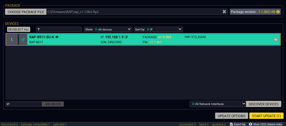
Step 3. Check the update parameters.

DIFFERENCE:The appearing settings are device-dependent and can be different device by device.
Clicking on the Update Options button, special settings will be available like:
▪Creating a backup about the configuration,
▪Restore the configuration or reloading the factory default settings after the firmware update,
▪Uploading the default Miniweb (if available)
▪Enter the password for the Cleartext login. #builtinweb #miniweb #web
INFO:Hereby entered password will be used for all the selected devices where the Cleartext login is enabled. If the password is incorrect, a window will appear to get the correct one at each device during the update.
Please arrange the settings carefully.
Step 4. Start the update and wait until it is finished.

Click on the Start Update button to start the procedure. The status is shown in percent in the right side of the device line and the overall process in the bottom progress bar.
If the Cleartext login is enabled and you did not enter the password in the Parameters window (or it is incorrect) a window will appear to get the password at each device.
INFO:The device might reboot during the firmware update procedure.

The log about the updating process can be displayed in a new window by pressing the button. When the progress bar reaches 100% (Done is displayed at all devices), the update of all devices are finished successfully and a message appears; you can close the software.

Step 5. Wait until the unit reboots with the new firmware.
Once the firmware update procedure is completed, the device is rebooted with the new firmware. Shutting down and restarting the device is recommended.
8.5. Command Line Interface (CLI)
DIFFERENCE:The Command Line Interface is available from LDU2 v2.9.0b9.
The CLI of the LDU2 software is a simple tool for creating scriptable device updates without the need of human interactions. It allows batch updating with the same features which are available in case of GUI usage. #new
8.5.1. How to Run
Running under Windows® OS
The installer of LDU2 puts the following file into the installation folder:
LightwareDeviceUpdaterV2_CLI.cmd
CLI is available by this file, the exe is not suitable for that purpose. Open a command line window to execute or test the features directly.
Step 1.Open an Explorer window where the cmd file is located, the default is:
c:\Program Files (x86)\Lightware\Lightware Device Updater V2\LightwareDeviceUpdaterV2_CLI.cmd.
Step 2.Click on the address line (highlighed with blue in the picture), type cmd.exe and press enter. The command interpreter window of Windows is opened at the path of the LDU2 install folder.

Step 3.Now you can use the LightwareDeviceUpdaterV2_CLI.cmd file with the commands and options which are described in the coming sections:
Running under Linux
The Command Line Interface under Linux Operating Systems can be run by the following:
LightwareDeviceUpdaterV2.sh
Runing an update:
bash LightwareDeviceUpdaterV2.sh update --ip 172.24.5.27 --package ~/Downloads/tps-tx200_1.3.1b3.lfp2
The commands and options are the same under Windows® and Linux, too. Following sections contain examples with LightwareDeviceUpdaterV2_CLI.cmd.
8.5.2. How to Use
Command Structure
The commands can be run over CLI by the following way:
LightwareDeviceUpdaterV2_CLI.cmd [command] [options]
[Command]: a certain command described in the coming sections; only one command can be run at a time
[Options]: mandatory and/or optional parameters of the command, if any. Optional parameters have a default value, which can be found at each affected command. You only have to define the parameter if you want to apply a different value. The order of the options is arbitrary.
Important Notes
▪CLI is case-sensitive (including commands, options and other parameters).
▪There is no limit regarding the number of the devices to update. At most 20 devices are updated simoultaneously, when one of them is finished, the following (21st) will be started automatically.
▪If an update is failed, the IP address of the affected device(s) are listed at the end.
8.6. CLI Commands
INFO:The commands and options described in the following sections are the same under Windows® and Linux, too. The examples contain LightwareDeviceUpdaterV2_CLI.cmd.
About the Examples
▪Sent command is in blue, response is in grey.
▪If the response in practice is longer than listed in the example, this symbol can be seen: [...].
8.6.1. Help
The defined commands and options can be listed by the help command.
Command
LightwareDeviceUpdaterV2_CLI.cmd help
Example
C:\Program Files (x86)\Lightware\Lightware Device Updater V2>LightwareDeviceUpdaterV2_CLI.cmd help
C:\Program Files (x86)\Lightware\Lightware Device Updater V2>lib\jre\bin\java.exe -jar lib\ldu2.jar help
Command line usage:
Win: LightwareDeviceUpdaterV2_CLI.cmd [command] [options]
Linux: LightwareDeviceUpdaterV2.sh [command] [options]
Commands:
* help
* version
* update
* deviceInfo
* restore
* packageOptions
[...]
8.6.2. LDU2 Version
The response shows the version of the LDU2 and the version of the Script API (the Application Programming Interface that is used by the LDU2 and the script).
Command
LightwareDeviceUpdaterV2_CLI.cmd version
Example
C:\Program Files (x86)\Lightware\Lightware Device Updater V2>LightwareDeviceUpdaterV2_CLI.cmd version
C:\Program Files (x86)\Lightware\Lightware Device Updater V2>lib\jre\bin\java.exe -jar lib\ldu2.jar version
LDU2 version: 2.9.0b9
Script API version: 1.3.9
8.6.3. Check For New LDU2 Version
The following command can be used to check if an update of LDU2 is available. This is just a request, since the CLI is not suitable for handling the complete installer of the software.
Command
LightwareDeviceUpdaterV2_CLI.cmd checkForUpdates
Example 1
c:\Program Files (x86)\Lightware\Lightware Device Updater V2>LightwareDeviceUpdaterV2_CLI.cmd checkForUpdates
c:\Program Files (x86)\Lightware\Lightware Device Updater V2>lib\jre\bin\java.exe -jar lib\ldu2.jar checkForUpdates
Current LDU2 version: 2.9.1b1
LDU2 is up-to-date
Example 2
c:\Program Files (x86)\Lightware\Lightware Device Updater V2>LightwareDeviceUpdaterV2_CLI.cmd checkForUpdates
c:\Program Files (x86)\Lightware\Lightware Device Updater V2>lib\jre\bin\java.exe -jar lib\ldu2.jar checkForUpdates
Current LDU2 version: 2.9.1b1
New version is available online: v2.9.2b2
Download URL: http://update.lightware.hu/ldu2/lwr/v2.9.2b2/install_LDU2_v2.9.2b2.exe
8.6.4. Device Info
The most important information about the selected device is displayed; see the example for more details.
Command
LightwareDeviceUpdaterV2_CLI.cmd deviceInfo [options]
Options
|
Option |
Description |
Required? |
|
-i or --ip |
List of IP addresses of devices to be updated |
one of them is mandatory |
|
-n or --hostName |
List of host names of devices to be updated |
|
|
-v or --packageVersion |
Shows installed package version only |
optional |
Example 1
C:\Program Files (x86)\Lightware\Lightware Device Updater V2>LightwareDeviceUpdaterV2_CLI.cmd deviceInfo --ip 192.168.1.14
C:\Program Files (x86)\Lightware\Lightware Device Updater V2>lib\jre\bin\java.exe -jar lib\ldu2.jar deviceInfo --ip 192.168.1.14
Product name: UMX-TPS-TX140K
IP address: 192.168.1.14
Serial number: 00006363
MAC address: a8:d2:36:ff:63:63
Part number: 91540050
Device label: UMX-TPS-TX140K
Package version: v1.5.0b4
CPU FW version: v1.5.0b4
HW version: V20_DAX0
Operation mode: Application mode
Example 2
C:\Program Files (x86)\Lightware\Lightware Device Updater V2>LightwareDeviceUpdaterV2_CLI.cmd deviceInfo --ip 192.168.1.14 --packageVersion
C:\Program Files (x86)\Lightware\Lightware Device Updater V2>lib\jre\bin\java.exe -jar lib\ldu2.jar deviceInfo --ip 192.168.1.14 --packageVersion
v1.1.1b2
8.6.5. Update
This command can be used to update the firmware of the devices.
Command
LightwareDeviceUpdaterV2_CLI.cmd update [options]
Options
|
Option |
Description |
Required? |
|
-p or --package |
The path of the firmware package file |
yes |
|
-i or --ip |
List of IP addresses of devices to be updated |
one of them is mandatory |
|
-n or --hostName |
List of host names of devices to be updated |
|
|
-b or --backupFolder |
Folder to create device configuration backup at. Default: USER_HOME/.ldu2/backup |
optional |
|
-f or --factoryDefault |
Apply factory reset during device update. Default: false |
optional |
|
-r or --reportProgress |
Report update progress in percentage form. Default: false |
optional |
|
Package-specific options |
Certain LFP2 packages have features which can be applied at this command |
optional |
ATTENTION!The configuration is restored automatically if the factory default option is not applied in the update command.In that case, there is no need to run the restore command after the update.
Example
C:\Program Files (x86)\Lightware\Lightware Device Updater V2>LightwareDeviceUpdaterV2_CLI.cmd update --ip 192.168.1.14 --package c:\Firmwares\rap_v1.2.0b3.lfp2 --reportProgress
C:\Program Files (x86)\Lightware\Lightware Device Updater V2>lib\jre\bin\java.exe -jar lib\ldu2.jar update --ip 192.168.1.14 --package c:\Firmwares\rap_v1.2.0b3.lfp2 --reportProgress
[2021-05-14 12:52:51.597] [ INFO] [ main] - Device IPs: [192.168.1.14]
[2021-05-14 12:52:55.786] [ INFO] [ main] - All the selected devices are accessible over the network.
[2021-05-14 12:52:56.032] [ INFO] [ main] - All the selected devices are compatible with the specified package.
[2021-05-14 12:52:56.600] [ INFO] [ 192.168.1.14] - Package version: 1.5.0b4
[2021-05-14 12:52:56.780] [ INFO] [ 192.168.1.14] - Login functionality is currently not enabled.
[2021-05-14 12:52:56.816] [ INFO] [ 192.168.1.14] - Creating backup of device settings...
[2021-05-14 12:53:00.517] [ INFO] [ 192.168.1.14] - Backup HTTP enable properties
[2021-05-14 12:53:01.051] [ INFO] [ProgressReporter] - Progress: 2%
[2021-05-14 12:53:02.928] [ INFO] [ 192.168.1.14] - HTTP and HTTP post have got enabled on port 80
[2021-05-14 12:53:03.080] [ INFO] [ 192.168.1.14] - No miniweb file is found on the device.
[2021-05-14 12:53:05.566] [ INFO] [ 192.168.1.14] - HTTP and HTTP post properties have got restored on port 80
[2021-05-14 12:53:05.613] [ INFO] [ 192.168.1.14] - Switching device into bootload mode...
[2021-05-14 12:53:06.053] [ INFO] [ProgressReporter] - Progress: 5%
[...]
The lines containing "ProgressReporter" can be enabled optionally. If it is enabled, the current state is displayed in every 5 seconds.
Restores device configuration from a backup file.
TIPS AND TRICKS:This command can be used for uploading a configuration to numerous devices (aka Configuration cloning by CLI).
Command
LightwareDeviceUpdaterV2_CLI.cmd restore [options]
Options
|
Option |
Description |
Required? |
|
-i or --ip |
List of IP addresses of devices to be updated |
one of them is mandatory |
|
-n or --hostName |
List of host names of devices to be updated |
|
|
-b or --backupFile |
The path of the configuration backup file |
yes |
|
-k or --keepOriginalIp |
Do not override the network settings of the device with the ones in the backup file. It comes in handy when multiple devices' configuration is being restored from a single backup file. Default: false |
optional |
ATTENTION!The configuration is restored automatically if the factory default option is not applied in the update command.In that case, there is no need to run the restore command after the update.
Example
C:\Program Files (x86)\Lightware\Lightware Device Updater V2>LightwareDeviceUpdaterV2_CLI.cmd restore --ip 192.168.1.14 --backupFile c:\My_backup\backup_RAC-B501_SN00006363.lw3 --keepOriginalIp
C:\Program Files (x86)\Lightware\Lightware Device Updater V2>lib\jre\bin\java.exe -jar lib\ldu2.jar restore --ip 192.168.1.14 --backupFile c:\My_backup\backup_RAC-B501_SN00006363.lw3 --keepOriginalIp
[2021-05-14 14:11:04.631] [ INFO] [ main] - Executing configuration restore...
[2021-05-14 14:11:04.645] [ INFO] [ main] - Device IPs: [192.168.1.14]
INFO:The firmware package checks the backup data before the restore procedure and if it is necessary, a conversion is applied to avoid incompatibility problems between the firmware versions. In that case, two backup files are created: the original and a new one with "_converted" suffix. Using the last one for restoring is recommended.
Shows package-specific update options.
Command
LightwareDeviceUpdaterV2_CLI.cmd packageOptions [options]
Options
|
Option |
Description |
Required? |
|
-p or --package |
The path of the firmware package file |
yes |
Example
C:\Program Files (x86)\Lightware\Lightware Device Updater V2>LightwareDeviceUpdaterV2_CLI.cmd packageOptions --package c:\Firmwares\rap_v1.2.0b3.lfp2
C:\Program Files (x86)\Lightware\Lightware Device Updater V2>lib\jre\bin\java.exe -jar lib\ldu2.jar packageOptions --package c:\Firmwares\rap_v1.2.0b3.lfp2
Backup and restore options:
--skipPresetsAtRestore : if true, device presets will not be restored. (Default: false)
--uploadDefaultMiniWeb : if true and no custom miniweb is present on the device, the default built-in miniweb will be uploaded to the device. (Default: false)
Login options:
--clearTextLoginPw : The cleartext login password used when updating devices. (Default: empty string)
Test options:
--test : if true, no update will be performed, communication with the device will be tested. (Default: false)
C:\Program Files (x86)\Lightware\Lightware Device Updater V2>
Package option example can be seen in the following section.
8.6.8. Complex Examples
Example 1
The following options applied:
▪Firmware is updated
▪Factory default settings restored
C:\Program Files (x86)\Lightware\Lightware Device Updater V2>LightwareDeviceUpdaterV2_CLI.cmd update --ip 192.168.1.14 --factoryDefault --package c:\Firmwares\rap_v1.2.0b3.lfp2
C:\Program Files (x86)\Lightware\Lightware Device Updater V2>lib\jre\bin\java.exe -jar lib\ldu2.jar update --ip 192.168.1.14 --factoryDefault --package c:\Firmwares\rap_v1.2.0b3.lfp2
[2021-05-14 14:20:26.242] [ INFO] [ main] - Device IPs: [192.168.1.14]
[2021-05-14 14:20:29.860] [ INFO] [ main] - All the selected devices are accessible over the network.
[2021-05-14 14:20:30.129] [ INFO] [ main] - All the selected devices are compatible with the specified package.
[2021-05-14 14:20:30.709] [ INFO] [ 192.168.1.14] - Package version: 1.2.0b3
[2021-05-14 14:20:30.861] [ INFO] [ 192.168.1.14] - Login functionality is currently not enabled.
[2021-05-14 14:20:30.913] [ INFO] [ 192.168.1.14] - Switching device into bootload mode...
[2021-05-14 14:20:51.497] [ INFO] [ 192.168.1.14] - Gathering UID information from device...
[2021-05-14 14:20:51.881] [ INFO] [ 192.168.1.14] - UID info - Device IP: 192.168.1.14 Product name: RAC-B501 Product part number: 91540050 Serial number: 00006363 Hardware version: V20_DAX0 MAC address: A8:D2:36:FF:63:63
[2021-05-14 14:20:52.224] [ INFO] [ 192.168.1.14] - Package version on device: 1.5.0b4 r66
[2021-05-14 14:20:52.259] [ INFO] [ 192.168.1.14] - Updating RAP series application fw - part 1...
[2021-05-14 14:20:52.595] [ INFO] [ 192.168.1.14] - [rap-f427.bin.ER_IROM1]'s current version on device: 1.5.0b4 r56
[2021-05-14 14:20:52.597] [ INFO] [ 192.168.1.14] - [rap-f427.bin.ER_IROM1]'s version in the package: 1.5.0b4 r56
[2021-05-14 14:21:09.260] [ INFO] [ 192.168.1.14] - [rap-f427.bin.ER_IROM1]'s firmware version updated in FVS EEPROM.
[2021-05-14 14:21:09.263] [ INFO] [ 192.168.1.14] - Updating rap series application fw - part 2...
[2021-05-14 14:21:09.590] [ INFO] [ 192.168.1.14] - [rap-f427.bin.ER_IROM2]'s current version on device: 1.5.0b4 r56
[2021-05-14 14:21:09.591] [ INFO] [ 192.168.1.14] - [rap-f427.bin.ER_IROM2]'s version in the package: 1.5.0b4 r56
[2021-05-14 14:21:30.832] [ INFO] [ 192.168.1.14] - [rap-f427.bin.ER_IROM2]'s firmware version updated in FVS EEPROM.
[2021-05-14 14:21:30.833] [ INFO] [ 192.168.1.14] - Updating VS100TX fw...
[2021-05-14 14:21:31.161] [ INFO] [ 192.168.1.14] - [vs100_tx.bin]'s current version on device: 1.1.0b0 r0
[2021-05-14 14:21:31.162] [ INFO] [ 192.168.1.14] - [vs100_tx.bin]'s version in the package: 1.1.0b0 r63
[2021-05-14 14:21:44.106] [ INFO] [ 192.168.1.14] - [vs100_tx.bin]'s firmware version updated in FVS EEPROM.
[2021-05-14 14:21:44.107] [ INFO] [ 192.168.1.14] - Updating PS171 FW...
[2021-05-14 14:21:44.433] [ INFO] [ 192.168.1.14] - [tps_family_ps171.bin]'s current version on device: 1.0.6b0 r0
[2021-05-14 14:21:44.434] [ INFO] [ 192.168.1.14] - [rap_family_ps171.bin]'s version in the package: 1.0.6b0 r522
[2021-05-14 14:22:00.612] [ INFO] [ 192.168.1.14] - [rap_family_ps171.bin]'s firmware version updated in FVS EEPROM.
[2021-05-14 14:22:06.740] [ INFO] [ 192.168.1.14] - Setting system information...
[2021-05-14 14:22:12.862] [ INFO] [ 192.168.1.14] - Starting application...
[2021-05-14 14:23:56.190] [ INFO] [ 192.168.1.14] - Done
All 1 update(s) finished successfully.
Example 2
The following options applied:
▪Cleartext login password is applied
▪Custom backup folder is set
▪Current configuration is saved
▪Firmware is updated and saved configuration is restored
C:\Program Files (x86)\Lightware\Lightware Device Updater V2>LightwareDeviceUpdaterV2_CLI.cmd update --ip 192.168.1.14 --package c:\Firmwares\rap_v1.2.0b3.lfp2 --backupFolder c:\My_backup --clearTextLoginPw qwer1234
C:\Program Files (x86)\Lightware\Lightware Device Updater V2>lib\jre\bin\java.exe -jar lib\ldu2.jar update --ip 192.168.1.14 --package c:\Firmwares\rap_v1.2.0b3.lfp2 --backupFolder c:\My_backup --clearTextLoginPw qwer1234
[2021-05-14 14:39:23.243] [ INFO] [ main] - Device IPs: [192.168.1.14]
[2021-05-14 14:39:26.379] [ WARN] [ pool-2-thread-1] - NetworkMask property is not available. Cannot determine whether the device is on the same network or not.
[2021-05-14 14:39:26.466] [ WARN] [ pool-2-thread-1] - Bonjour device builder error messages: [object Array]
[2021-05-14 14:39:26.535] [ INFO] [ main] - All the selected devices are accessible over the network.
[2021-05-14 14:39:26.753] [ INFO] [ main] - All the selected devices are compatible with the specified package.
[2021-05-14 14:39:27.307] [ INFO] [ 192.168.1.14] - Package version: 1.5.0b4
[2021-05-14 14:39:27.441] [ INFO] [ 192.168.1.14] - Logged in successfully.
[2021-05-14 14:39:27.471] [ INFO] [ 192.168.1.14] - Creating backup of device settings...
[2021-05-14 14:39:31.010] [ INFO] [ 192.168.1.14] - Backup HTTP enable properties
[2021-05-14 14:39:33.462] [ INFO] [ 192.168.1.14] - HTTP and HTTP post have got enabled on port 80
[2021-05-14 14:39:33.656] [ INFO] [ 192.168.1.14] - No miniweb file is found on the device.
[2021-05-14 14:39:36.091] [ INFO] [ 192.168.1.14] - HTTP and HTTP post properties have got restored on port 80
[2021-05-14 14:39:36.186] [ INFO] [ 192.168.1.14] - Switching device into bootload mode...
[2021-05-14 14:39:56.561] [ INFO] [ 192.168.1.14] - Gathering UID information from device...
[2021-05-14 14:39:56.937] [ INFO] [ 192.168.1.14] - UID info - Device IP: 192.168.1.14 Product name: RAC-B501 Product part number: 91540050 Serial number: 00006363 Hardware version: V20_DAX0 MAC address: A8:D2:36:FF:63:63
[2021-05-14 14:39:57.301] [ INFO] [ 192.168.1.14] - Package version on device: 1.5.0b4 r66
[2021-05-14 14:39:57.714] [ INFO] [ 192.168.1.14] - Updating RAP series application fw - part 1...
[2021-05-14 14:39:58.052] [ INFO] [ 192.168.1.14] - [rap-f427.bin.ER_IROM1]'s current version on device: 1.5.0b4 r56
[2021-05-14 14:39:58.053] [ INFO] [ 192.168.1.14] - [rap-f427.bin.ER_IROM1]'s version in the package: 1.5.0b4 r56
[2021-05-14 14:40:14.848] [ INFO] [ 192.168.1.14] - [rap-f427.bin.ER_IROM1]'s firmware version updated in FVS EEPROM.
[2021-05-14 14:40:14.850] [ INFO] [ 192.168.1.14] - Updating UMX-TPS-TX100 series application fw - part 2...
[2021-05-14 14:40:15.178] [ INFO] [ 192.168.1.14] - [rap-f427.bin.ER_IROM2]'s current version on device: 1.5.0b4 r56
[2021-05-14 14:40:15.179] [ INFO] [ 192.168.1.14] - [rap-f427.bin.ER_IROM2]'s version in the package: 1.5.0b4 r56
[2021-05-14 14:40:36.511] [ INFO] [ 192.168.1.14] - [rap-f427.bin.ER_IROM2]'s firmware version updated in FVS EEPROM.
[2021-05-14 14:40:36.512] [ INFO] [ 192.168.1.14] - Updating VS100TX fw...
[2021-05-14 14:40:36.837] [ INFO] [ 192.168.1.14] - [vs100_tx.bin]'s current version on device: 1.1.0b0 r0
[2021-05-14 14:40:36.839] [ INFO] [ 192.168.1.14] - [vs100_tx.bin]'s version in the package: 1.1.0b0 r63
[2021-05-14 14:40:49.849] [ INFO] [ 192.168.1.14] - [vs100_tx.bin]'s firmware version updated in FVS EEPROM.
[2021-05-14 14:40:49.851] [ INFO] [ 192.168.1.14] - Updating PS171 FW...
[2021-05-14 14:40:50.177] [ INFO] [ 192.168.1.14] - [rap_family_ps171.bin]'s current version on device: 1.0.6b0 r0
[2021-05-14 14:40:50.179] [ INFO] [ 192.168.1.14] - [rap_family_ps171.bin]'s version in the package: 1.0.6b0 r522
[2021-05-14 14:41:06.386] [ INFO] [ 192.168.1.14] - [tps_family_ps171.bin]'s firmware version updated in FVS EEPROM.
[2021-05-14 14:41:12.514] [ INFO] [ 192.168.1.14] - Setting system information...
[2021-05-14 14:41:18.637] [ INFO] [ 192.168.1.14] - Starting application...
[2021-05-14 14:43:03.605] [ INFO] [ 192.168.1.14] - Waiting for VS100...
[2021-05-14 14:43:05.237] [ INFO] [ 192.168.1.14] - Restoring device settings from the following backup file: c:\My_backup\backup_91540050_00006363_2021-05-14_14-39-28_converted.lw3 ...
[2021-05-14 14:43:14.325] [ INFO] [ 192.168.1.14] - Device settings have been restored
[2021-05-14 14:43:14.358] [ INFO] [ 192.168.1.14] - Resetting device...
[2021-05-14 14:43:19.071] [ INFO] [ 192.168.1.14] - Done
All 1 update(s) finished successfully.
Example 3
The following options applied:
▪Cleartext login password is applied
▪Custom backup folder is set
▪Current configuration is saved
▪Firmware is not updated but the process and the connection is tested
C:\Program Files (x86)\Lightware\Lightware Device Updater V2>LightwareDeviceUpdaterV2_CLI.cmd update --test --ip 192.168.1.14 --package c:\Firmwares\rap_v1.2.0b3.lfp2 --backupFolder c:\My_backup --clearTextLoginPw qwer1234
C:\Program Files (x86)\Lightware\Lightware Device Updater V2>lib\jre\bin\java.exe -jar lib\ldu2.jar update --test --ip 192.168.1.14 --package c:\Firmwares\rap_v1.2.0b3.lfp2 --backupFolder c:\My_backup --clearTextLoginPw qwer1234
[2021-05-14 14:45:37.351] [ INFO] [ main] - Device IPs: [192.168.1.14]
[2021-05-14 14:45:40.396] [ WARN] [ pool-2-thread-1] - NetworkMask property is not available. Cannot determine whether the device is on the same network or not.
[2021-05-14 14:45:40.481] [ WARN] [ pool-2-thread-1] - Bonjour device builder error messages: [object Array]
[2021-05-14 14:45:40.551] [ INFO] [ main] - All the selected devices are accessible over the network.
[2021-05-14 14:45:40.748] [ INFO] [ main] - All the selected devices are compatible with the specified package.
[2021-05-14 14:45:41.347] [ INFO] [ 192.168.1.14] - PASSED - Test #01 - Communication over LW3
[2021-05-14 14:45:41.427] [ INFO] [ 192.168.1.14] - PASSED - Test #02 - Cleartext login - PW is correct
[2021-05-14 14:45:41.474] [ INFO] [ 192.168.1.14] - Creating backup of device settings...
[2021-05-14 14:45:45.010] [ INFO] [ 192.168.1.14] - Backup HTTP enable properties
[2021-05-14 14:45:47.417] [ INFO] [ 192.168.1.14] - HTTP and HTTP post have got enabled on port 80
[2021-05-14 14:45:47.620] [ INFO] [ 192.168.1.14] - No miniweb file is found on the device.
[2021-05-14 14:45:50.058] [ INFO] [ 192.168.1.14] - HTTP and HTTP post properties have got restored on port 80
[2021-05-14 14:45:50.060] [ INFO] [ 192.168.1.14] - PASSED - Test #03 - Configuration and/or device preset backup created
[2021-05-14 14:45:50.080] [ INFO] [ 192.168.1.14] - Switching device into bootload mode...
[2021-05-14 14:45:51.721] [ INFO] [ 192.168.1.14] - PASSED - Test #04 - Switch device into bootloader mode
[2021-05-14 14:46:09.050] [ INFO] [ 192.168.1.14] - PASSED - Test #05 - Communication with bootloader
[2021-05-14 14:46:09.063] [ INFO] [ 192.168.1.14] - Gathering UID information from device...
[2021-05-14 14:46:09.403] [ INFO] [ 192.168.1.14] - PASSED - Test #06 - TFTP file transfer
[2021-05-14 14:46:22.638] [ INFO] [ 192.168.1.14] - PASSED - Test #07 - Start application FW
[2021-05-14 14:46:22.681] [ INFO] [ 192.168.1.14] - Done
All 1 update(s) finished successfully.
8.6.9. Exit Codes
There is a return value in all cases, when a command run is finished. Currently, three codes are defined:
|
Code |
Displayed text |
Description |
|
0 |
N/A |
The update performed successfully |
|
1 |
Update error (ErrorCode:1) |
The error happened during the update |
|
2 |
CLI error (ErrorCode:2 |
The error happened before starting the update |
The error line contains further information about the error.
Querying the Exit Code under Windows®
c:\Program Files (x86)\Lightware\Lightware Device Updater V2\echo %errorlevel%
0
Querying the Exit Code under Linux
echo $?
0
So if this value is queried after the update and it is 0, the update performed successfully.
8.7. If the Update is not successful
▪Restart the process and try the update again.
▪If the device cannot be switched to bootload (firmware update) mode, you can do that manually as written in the User's manual of the device. Please note that backup and restore cannot be performed in this case.
▪If the backup cannot be created for some reason, you will get a message to continue the process without backup or stop the update. A root cause can be that the desired device is already in bootload (firmware update) mode, thus, the normal operation mode is suspended and backup cannot be made.
▪If an update is not successful, the Export log button becomes red. If you press the button, you can download the log file as a ZIP package which can be sent to Lightware Support if needed. The log files contain useful information about the circumstances to find the root cause. #bootload
Usually, if the system seems not to transport the signal as expected, the best strategy for troubleshooting is to check signal integrity through the whole signal chain starting from source side and moving forward to device end.
9.1. Use Cases
At first, check front panel LEDs and take the necessary steps according to their states. For more information about status, LEDs refer to RAP-B511 Series and Rear View sections.
|
Symptom |
Root cause |
Action |
|
RS-232 signal |
||
|
Connected serial device does not respond |
Cable connection problem |
Check the connectors to fit well; check the wiring of the plugs. |
|
RS-232 settings are different |
Check the port settings of the RAP-B511 and the connected serial device(s). |
|
|
RS-232 mode is not right |
Check the RS-232 mode settings (control, command injection, or disconnected) |
|
|
Network |
||
|
No LAN connection can be established |
Incorrect IP address is set (fix IP) |
Use dynamic IP address by enabling DHCP option. |
|
Restore the factory default settings (with fix IP). |
||
|
IP address conflict |
Check the IP address of the other devices, too. |
|
|
GPIO |
||
|
Connected device does not respond |
Cable connection problem |
Check the connectors to fit well; check the wiring of the plugs. |
|
Output level cannot be changed |
The direction of the selected pin is set to input |
Check and modify the direction setting of the desired pin |
|
Miscellaneous |
||
|
Front panel buttons are out of operation |
Buttons are set as locked in LDC |
Unlock the buttons |
9.2. How to Speed Up the Troubleshooting Process

Lightware’s technical support team is always working hard to provide the fastest support possible. Our team’s response time is one of the best in the industry and in the toughest of cases we can directly consult with the hardware or software engineer who designed the product to get the information from the most reliable source.
However, the troubleshooting process can be even faster… with your help.
There are certain pieces of information that push us in the right direction to finding the root cause of the problem. If we receive most of this information in the first e-mail or it is gathered at the time when you call us, then there is a pretty high chance that we will be able to respond with the final solution right away.
This information is the following:
▪Schematic (a pdf version is preferred, but a hand drawing is sufficient).
▪Serial number(s) of the device(s) (it is either printed somewhere on the box or you can query it in the Device Controller software or on the built-in website).
▪Firmware versions of the devices (please note that there may be multiple CPUs or controllers in the device and we need to know all of their firmware versions, a screenshot is the best option).
▪Cable lengths and types (in our experience, it’s usually the cable).
▪Patch panels, gender changers or anything else in the signal path that can affect the transmission.
▪Signal type (resolution, refresh rate, color space, deep color).
▪Emulated EDID(s) (please save them as file and send them to us).
▪Actions to take in order to re-create the problem (if we cannot reproduce the problem, it is hard for us to find the cause).
▪Photo or video about the problem (‘image noise’ can mean many different things, it’s better if we see it too).
▪Error logs from the Device Controller software.
▪In the case of Event Manager issue the event file and/or backup file from the Device Controller software.
The more of the above information you can give us the better. Please send these information to the Lightware Support Team (support@lightware.com) to speed up the troubleshooting process.
Tables, drawings, guides, hashtag keyword list and technical details as follows:
10.1. Specifications
General
|
Compliance |
CE, UKCA |
|
EMC (emission) |
EN 55032:2015+A1:2020 |
|
EMC (immunity) |
EN 55035:2017+A11:2020 |
|
RoHS |
EN 63000:2018 |
|
Electrical safety |
EN 62368-1:2020 |
|
Warranty |
3 years |
|
Operating temperature |
0° to +50°C (+32° to +122°F) |
|
Operating temperature |
0 to +50˚C (+32 to +122˚F) |
|
Operating humidity |
10% to 90%, non-condensing |
|
Cooling |
Passive |
Power
|
Power supply option |
Power adaptor / PoE |
|
Power consumption (supplied by local power) |
1.78W |
|
Power consumption (supplied by PoE) |
1.87W |
|
Heat dissipation (max) |
7 BTU/h |
|
Power over Ethernet (PoE) |
via Ethernet port (IEEE802.3af) |
Power adaptor (not supplied)
|
Supported power source |
100-240 V AC; 50/60 Hz |
|
Supplied power |
48V DC, 0.5A |
|
AC power plug |
Interchangable (EU, UK, JP/US, AUS/NZ) |
|
DC power plug |
2-pole Phoenix connector |
Enclosure
RAP-B511 series
|
Rack mountable |
No |
|
Enclosure material |
1 mm steel |
|
Dimensions in mm (-EU) |
152 W x 58.1 D* x 82 H |
|
Dimensions in inch (-EU) |
6 W x 2.3 D* x 3.3 H |
|
Dimensions in mm (-UK) |
140 W x 58.1 D* x 80 H |
|
Dimensions in mm (-UK) |
5.6 W x 2.3 D* x 3.2 H |
|
Dimensions in mm (-US) |
115.9 W x 58.1 D* x 115.9 H |
|
Dimensions in mm (-US) |
4.6 W x 2.3 D* x 4.6 H |
|
Weight (-EU) |
412 g (0.92 lb) |
|
Weight (-UK) |
380 g (0.84 lb) |
|
Weight (-US) |
433 g (0.95 lb) |
* with the front panel and rotary knob
RAC-B501
|
Rack mountable |
Yes, with 1U high rack shelf |
|
Enclosure material |
1 mm steel |
|
Dimensions in mm |
100.4 W x 98.4 D x 26 H |
|
Dimensions in inch |
3.9 W x 3.8 D 1 H |
|
Weight |
329 g (0.72 lb) |
Control Ports
Control Ethernet
|
Connector type |
RJ45 female connector |
|
Ethernet data rate |
10/100Base-T, full duplex with autodetect |
|
Power over Ethernet (PoE) |
PoE in (1x), PoE out (1x) |
RS-232
|
Connector type |
3-pole Phoenix connector |
|
Baud rates |
between 4800 and 115200 baud |
|
Data bits |
8 or 9 |
|
Parity |
None / Odd / Even |
|
Stop bits |
1 / 1.5 / 2 |
|
Output voltage: Low / High level |
3 - 15V / -15V - 3V |
Infrared port **
|
Input |
Built-in IR detector |
** Only for RAP-B511 series models
GPIO port
|
Connector type |
4-pole Phoenix connector |
|
Number of configurable pins |
3 |
|
Port direction |
Input or output |
INFO:Specifications are subject to change without notice.
10.2. Factory Default Settings
|
Parameter |
Setting/Value |
|
Button settings |
|
|
Button enabled |
true |
|
Operation mode |
0 |
|
Interaction state |
true |
|
EnabLED |
true |
|
LED function for True state |
off |
|
LED function for False state |
off |
|
Button LED lowbright level |
2 |
|
Button LED highbright level |
5 |
|
Network settings |
|
|
IP address |
192.168.0.100 |
|
Subnet mask |
255.255.255.0 |
|
Static gateway |
192.168.0.1 |
|
DHCP |
Disabled |
|
LW2 port number |
10001 |
|
LW3 port number |
6107 |
|
HTTP port number |
80 |
|
RS-232 settings |
|
|
Control protocol |
LW2 |
|
Baud rate |
57600 |
|
Databits |
8 |
|
Parity |
No |
|
Stopbits |
1 |
|
Operation mode |
Command Injection |
|
Command injection port nr. |
8001 |
|
Recognizer delimiter |
0D0A |
|
Recognizer Timeout |
0 (disabled) |
|
Recognizer Active property timeout |
50 |
|
IR port settings - only for RAP-B511 series models |
|
|
Command injection status |
Enabled |
|
Command injection input port nr. |
9001 |
|
GPIO port settings |
|
|
Output level / Direction |
High / Input |
RS-232 Data Transmission
Room Automation Panel is built with 3-pole Phoenix connector. See the below examples of connecting to a DCE (Data Circuit-terminating Equipment) or a DTE (Data Terminal Equipment) type device:
|
Lightware device and a DCE D-SUB 9 - Phoenix |
Lightware device and a DTE D-SUB 9 - Phoenix |
|

|

|
INFO:The RAP-B511 series works as a DCE unit according to its pin-out.
10.4. Button Numbering

Dimensions are in mm.
10.5.1. RAP-B511 Series
RAP-B511-EU -K, -W, -S
INFO:All the RAP-B511-EU models have the same size.

RAP-B511-UK -K, -W, -S
INFO:All the RAP-B511-UK models have the same size.

RAP-B511-US -K, -W, -S
INFO:All the RAP-B511-US models have the same size.

10.5.2. RAC-B501
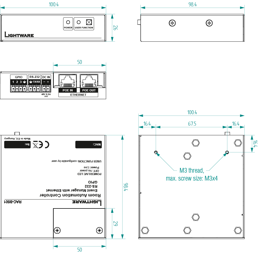
10.6. Supplied Button Labels for RAP-B511 series

10.7. Button Sizes for RAP-B511 series

The dimensions are in mm.
10.8. Applied Ports (Network Settings)
The following ports are necessary to pass via a network switch/firewall for a proper working between the device and the softwares:
|
Purpose/function |
Affected software |
Protocol |
Port nr. |
|
Firmware update TFTP |
LDU2 |
UDP |
69 |
|
UDP |
50000 |
||
|
Device Discovery |
LDC |
UDP |
224.0.0.251:5353 |
|
Remote IP |
LDC |
UDP |
230.76.87.82:37421 |
|
Find me (LMDMP) |
- |
UDP |
230.76.87.82:37422 |
|
LW2 protocol |
- |
TCP |
10001 |
|
LW3 protocol |
- |
TCP |
6107 |
|
HTTP port |
- |
TCP |
80 |
|
RS-232 command injection |
- |
TCP |
8001, 8002 |
|
IR command injection |
- |
TCP |
9001, 9002, 9003, 9004 |
10.9. Firmware Release Notes
The list below shows the released firmware packages with important notes.
v1.2.0b1
Release date: 2022-09-15
New feature:
▪Support new product: RAC-B501
v1.1.1b2
Release date: 2021-05-31
New feature:
▪Update Control USB interface driver.
Bugfix:
▪Fixed an IP address mode setting bug
v1.1.0b3
Release date: 2021-01-12
New feature:
▪Added AND operator for Event Manager Conditions (Advanced Control pack v3)
▪Added Condition triggering for Event Manager (Advanced Control pack v3)
▪Added Variable handling for Event Manager (Advanced Control pack v3)
▪Added Permanent TCP clients with configurable target IP address, and Message recognizer for TCP clients (Advanced Control pack v3)
▪Added LW3 command-salvo over Http POST (protocol.lw3) (Advanced Control pack v3)
▪Added Http message sending with sendHttpPost and sendHttpPut (target server IP, target filepath, header, body) (Advanced Control pack v3)
▪Added method to send Wake On LAN packet (Advanced Control pack v3)
▪Added cleartext login function (disabled by default) (Advanced Control pack v3)
▪Added MAC filtering (Advanced Control pack v3)
▪Added IP port and services filtering (Advanced Control pack v3)
▪Added Macro capability (running partial device preset with tags) (Advanced Control pack v3)
▪Added LMDMP (Lightware Multicast Device Management Protocol) feature.
▪Modified DeviceLabel property default text to LW_<productname>_<serialnum>
▪Added properties in root node: FirmwareVersion, PackageVersion, MacAddress.
▪Added property to indicate FeaturePackVersion (Advanced Control pack v3)
▪Added Condition detect on property change to anything in Event Manager (Advanced Control pack v3)
▪Added Network HostName property (default: lightware-<serialnum>).
▪Support for the factory reset button on the front panel.
Bugfix:
▪Improved network compatibility with 10.x.x.x IP address range.
▪Minor performance improvements and modifications.
▪Fixed issue with tick counter when the device is continuously operating for a very long time.
▪Unmute on volume change property added.
v1.0.3b2
Release date: 2020-05-21
Bugfix:
▪Cisco integration support
▪Minor built-in miniweb bugfixes
v1.0.2b2
Release date: 2019-09-17
Bugfix:
▪The setting of the device into factory default mode accidentally while operating the appliance has been ceased. In case of the device IP is unknown and no factory default hotkey is available, please connect the device to a computer using an USB cable.
v1.0.1b1
Release date: 2019-05-21
Bugfix:
▪Fixed a potential Backup restore LED status bug
v1.0.0b17
Release date: 2019-04-17
New feature:
▪Initial release
Known issue:
▪If the USB connection is broken accidentally, it occurs that the device lost the connection. Check the cable and reset the device.
10.10. Hashtag Keyword List
This user's manual contains keywords with hashtag (#) to help you find the relevant information as quick as possible.
The format of the keywords is the following:
#<keyword>
The usage of the keywords: use the Search function (Ctrl+F / Cmd+F) of your PDF reader application, type the # (hashtag) character and the wished keyword.
The #new special keyword indicates a new feature/function that has just appeared in the latest firmware or software version.
Example
#dhcp
This keyword is placed at the DHCP (dynamic IP address) setting in the front panel operation, the Lightware Device Controller (LDC) and the LW3 programmer's reference section.
The following list contains all hashtag keywords placed in the document with a short description belonging to them. The list is in alphabetical order by the hashtag keywords.
|
Hashtag Keyword |
Description |
|
#advancedview |
Advanced view / Terminal window |
|
#backup |
Configuration cloning (backup) |
|
#bootload |
Bootload mode setting |
|
#button |
Button configuration |
|
#buttonled |
Button LED configuration |
|
#buttonlock |
Front panel button lock setting |
|
#devicelabel |
Device label |
|
#dhcp |
Dynamic IP address (DHCP) setting |
|
#eventmanager |
Event manager |
|
#factory |
Factory default settings |
|
#firmwareversion |
Firmware version query |
|
#gpio |
GPIO realted settings |
|
#http |
Http post and put messaging, salvo commands |
|
#infra |
Infrared port related settings |
|
#infrared |
Infrared port related settings |
|
#ipaddress |
IP address related settings |
|
#label |
Device label |
|
#led |
Button LED configuration |
|
#lockbutton |
Front panel button lock setting |
|
#log |
System log |
|
#login |
Cleartext login feature |
|
#macfilter |
MAC filtering (IT security) |
|
#macro |
Macro-handling |
|
#message |
Message sending via communication ports |
|
#network |
Network (IP address) related settings |
|
#portblock |
IP port blocking (IT security) |
|
#producttype |
Product type query |
|
#protocol |
RS-232 protocol setting |
|
#real-time |
Time settings |
|
#reboot |
Restarting the device |
|
#recognizer |
RS-232 recognizer |
|
#restart |
Restarting the device |
|
#rotary |
Rotary configuration |
|
#rs232 |
RS-232 related settings |
|
#rs-232 |
RS-232 related settings |
|
#serial |
RS-232 related settings |
|
#serialnumber |
Serial number query |
|
#style |
Button style configuration |
|
#systemlog |
System log |
|
#tcprecognizer |
TCP message recognizer-related settings |
|
#terminal |
Advanced view / Terminal window |
|
#time |
Time settings |
|
#variables |
Variable-management |
|
#volume |
Rotary configuration |
10.11. Further Information
Limited Warranty Statement
1. Lightware Visual Engineering PLC (Lightware) warrants to all trade and end user customers that any Lightware product purchased will be free from manufacturing defects in both material and workmanship for three (3) years from purchase unless stated otherwise below. The warranty period will begin on the latest possible date where proof of purchase/delivery can be provided by the customer. In the event that no proof can be provided (empty ‘Date of purchase’ field or a copy of invoice), the warranty period will begin from the point of delivery from Lightware.
1.1. 25G and MODEX product series will be subject to a seven (7) year warranty period under the same terms as outlined in this document.
1.2. If during the first three (3) months of purchase, the customer is unhappy with any aspect of a Lightware product, Lightware will accept a return for full credit.
1.3. Any product that fails in the first six (6) months of the warranty period will automatically be eligible for replacement and advanced replacement where available. Any replacements provided will be warranted for the remainder of the original unit’s warranty period.
1.4. Product failures from six (6) months to the end of the warranty period will either be repaired or replaced at the discretion of Lightware. If Lightware chooses to replace the product then the replacement will be warranted for the remainder of the original unit’s warranty period.
2. The above-stated warranty and procedures will not apply to any product that has been:
2.1. Modified, repaired or altered by anyone other than a certified Lightware engineer unless expressly agreed beforehand.
2.2. Used in any application other than that for which it was intended.
2.3. Subjected to any mechanical or electrical abuse or accidental damage.
2.4. Any costs incurred for repair/replacement of goods that fall into the above categories (2.1., 2.2., 2.3.) will be borne by the customer at a pre-agreed figure.
3. All products to be returned to Lightware require a return material authorization number (RMA) prior to shipment and this number must be clearly marked on the box. If an RMA number is not obtained or is not clearly marked on the box, Lightware will refuse the shipment.
3.1. The customer will be responsible for in-bound and Lightware will be responsible for out-bound shipping costs.
3.2. Newly repaired or replaced products will be warranted to the end of the originally purchased products warranty period.
Document Revision History
|
Rev. |
Release date |
Changes |
Editor |
|
1.0 |
04-06-2019 |
Initial version |
Judit Barsony |
|
. . . |
|||
|
2.4 |
09-05-2023 |
Button lock information updated |
Nikolett Keindl |
|
2.5 |
12-12-2023 |
Specification updated |
Tamas Forgacs |
+36 1 255 3810
Lightware Visual Engineering PLC.
Peterdy 15, Budapest H-1071, Hungary
©2024 Lightware Visual Engineering. All rights reserved. All trademarks mentioned are the property of their respective owners. Specifications subject to change without notice.